
|
|
| Elliott Sound Products | Soft Start Circuits For High Inrush Loads |
 Main Index
Articles Index
Main Index
Articles Index

| WARNING: The circuits and techniques described here require experience with mains wiring. Do not attempt construction unless experienced and capable. Death or serious injury may result from incorrect wiring. |
|
PCBs are available for a soft-start project. Please see Project 39 for the details. This was one of the first published anywhere on the Net (in 1999), and many people worldwide have copied the original text from the project page to describe their own version, and explain why it's needed. Please note that some of the material from the project article is duplicated here, largely because it's appropriate for both articles. This article is a follow-on from Inrush Current Mitigation, and while the two articles share some details, there are also many different approaches looked at in each.
It's not only transformers that have a high inrush current. Motors are also affected, as are high powered filament lamps (although they are not as common as they used to be). Soft start circuits are routinely used with large motors, but the system isn't something that most people will ever see. I've worked on huge cast iron resistors that were used to 'soft-start' large motors used in pumping stations, but that is not an application that I'm going to entertain here (few people will ever see a large (350kW or more) motor starter).
Instead, this article concentrates on soft starting for transformer or electronic loads that are rated for up to 1kVA or so. These can create havoc in a home system if not tamed properly, and soft start is recommended for any power supply rated at more than 300VA. Note that I've used the term 'VA' rather than 'watts', because most loads that hobbyists will encounter have a poor power factor, and all transformers are rated in VA (volt/ amps), not watts. If you don't understand power factor, see the Power Factor article.
The optimum delay time for all circuits shown when used with transformers is around 100-150ms - sufficient for around 5-7 full cycles at 50Hz, or 6-9 cycles at 60Hz. A delay of up to 200ms is normally acceptable, but it is not recommended that the soft start resistors remain in circuit for more than around 500ms. It is quite alright to run a transformer to around 200-500% of full load current at start-up, and the formulae shown are based on a nominal 200% inrush. It is certainly possible to limit it further, but the resistor bank has to dissipate a great deal of power. Without a soft-start, inrush current can be so high as to be limited only by wiring resistance - well in excess of 50A is not at all uncommon for average sized 230V transformers or other high inrush loads.
It's worth pointing out that there are many soft start circuits published, with quite a few from China (and elsewhere) that use an 'off-line' transformerless power supply. These can be made to work well, but most have some serious limitations that are not immediately obvious. First and foremost amongst these is that when the power is turned off, there is often nothing to discharge the storage cap. A brief interruption to the mains supply (or even one lasting for a minute or more) may leave the circuit ready to energise the relay instantly when power is restored.
That means that after a short interruption, there is no soft start! The design of the PCB version of P39 in particular has been worked out to ensure that the timer resets very quickly (less than 150ms), and this is necessary to ensure that the soft start is applied every time the equipment is powered on, even with relatively quick on-off-on cycling (it may not happen all the time, but it will happen every so often). While the transformer will take the punishment, the fuse may not, potentially leading to 'nuisance' fuse failures or even failed bridge rectifiers.
It is certainly possible to include the additional circuitry needed for a complete off-line transformerless soft start, but it's not as simple as the circuits shown on the Net. It's dead easy to provide a simple delay circuit, but it takes more effort to ensure that it will have a consistent delay and will reset in a timely manner. Most of the ones I've seen have no reset capability at all. One that's available from China has such a long time delay that it's positively dangerous. Some also have mounting holes with inadequate clearance between the mains and mounting screws, which is potentially lethal unless nylon mounts are used.
Many of the alternatives (elsewhere) rely on the slow voltage rise across the main filter capacitor to directly energise the relay. This is a barely satisfactory solution (IMO), because the relay contacts will close more slowly than normal because of the slow voltage rise. The relay should be switched quickly to ensure proper contact closure every time the circuit is operated. The requirement for 'snap' action for relay operation and the need for a fast reset are at odds with each other unless a more complex circuit is used.
By their nature, relays tend towards a 'snap' action by default, due to the properties of the magnetic circuit. However, this doesn't change the fact that proper contact pressure and a positive wiping action of the contact surfaces may be impacted if the voltage risetime is too slow. A slowly falling coil voltage makes the contacts open with less 'authority' and may exacerbate contact erosion.
The reset time should be close to instantaneous, but up to 0.5 second will probably be acceptable in normal use. Having to wait for several seconds or minutes before the equipment can be powered on again with the soft start circuit functioning properly is simply unacceptable. This is an error that's even been made in commercial products, so a brief power interruption can cause the fuse to blow. That's a major nuisance, but it's intolerable if the fuse is internal and requires the unit to be disassembled to replace it.
All current measurements were taken using the Project 139A and/or Project 139 current monitors, which ensure that no direct connection to the mains is needed. Switching at the zero-crossing and peak AC waveform was done using a specialised test unit that I designed and built specifically for assessing inrush current on a variety of products.
When a large power amplifier or some other appliance with either a big transformer or a large filter capacitor (or both) is switched on, the initial current drawn from the mains can be many times that drawn even at full power. There are two main reasons for this, as follows ...
These phenomena are well known to manufacturers of very high power amps used in PA, and also to those who build industrial products, but 'soft start' circuits are not commonly used in consumer equipment. Anyone who has a large power amp - especially one that uses a toroidal transformer - will have noticed a momentary dimming of the lights when the amp is powered up. The current drawn is so high that other equipment is affected.
This high inrush current (as it is known) is stressful on many components in your amp, especially ...
It should come as no surprise to learn that a significant number of amplifier failures (especially PSU related faults) occur at power on (unless the operator does something foolish). This is exactly the same problem that causes your (incandescent) lights at home to 'blow' as you turn on the light switch. You rarely see a light bulb fail while you are quietly sitting there reading, it almost always happens at the moment that power is applied. It is exactly the same with power amplifiers.
NOTE: Do not attempt these circuits if you are unwilling to experiment - the relay operation must be 100% reliable, your mains wiring must be to an excellent standard, and some metalwork may be needed. There is nothing trivial about any circuit shown here (or any other circuit designed for the same purpose), despite apparent simplicity.
The circuits presented here are designed to limit inrush current to a safe value, which should usually be a maximum of about 200% of the full load capacity of the power transformer. Please be aware that there are important safety issues with these designs (as with all such circuits) - neglect these at your peril. In some cases, up to 500% of full power may be acceptable, and the decision as to which value to use is up to you. The transformer manufacturer may have some specific recommendations, and if so these should be followed.
The information here is aimed at primarily at transformers, but there are certainly other applications as well. It's entirely up to the reader to determine the suitability of any circuit for any application, and I can't (and won't) make specific recommendations for any other usage that you have in mind. If possible, verify that the item you wish to soft start will function normally if powered on using a slow voltage rise from a Variac. While most amplifiers and power supplies will behave, there are some that may not. These cannot use a soft start circuit!
It's worth mentioning that we generally tend to refer to power supplies using a mains transformer at normal 50/60Hz as 'linear', but in fact that's not true at all. The word 'linear' implies that the load presented to the mains is also linear (resistive loads are truly linear), but a transformer based power supply does no such thing. The waveform shown in Figure 9 (near the end of this page) shows the actual waveform of the mains current for the final two cycles, and it's obvious that it's anything but linear in the true meaning of the word. This is immaterial to the purpose of this article, but it's important to understand that terms used in electronics can take on 'new' meanings by common usage. This is one of them, and it can (and does) lead to confused thinking if you are unaware of the true nature of a transformer based rectifier and filter circuit, and its effect on the transformer input current.
The most obvious and readily available choice of current limiting device is a resistor. However, some care is necessary to ensure that the resistor can withstand the very high current (and instantaneous dissipation) that happen when a large transformer is turned on. There are several choices, with my preferred solution being to use three 5W resistors in parallel. There's a complete example calculation shown further below, but you may choose to ignore that and elect to use 3 x 150 ohm 5W resistors in parallel (230V), or 3 x 33 ohm 5W resistors in parallel for 120V.
There's nothing even remotely scientific about making a simple selection, but these values are verified in the example calculations below, and have been used by countless hobbyists in their P39 soft-start circuits. The important thing is that the resistors can handle the current. Although it's brief, it's also rather hard on a resistor's internals. A single 5W resistor certainly will not cope (I had one split in half during early testing), and while a heavy duty 50W or 100W part will probably survive, they are fairly expensive compared to the common 5W ceramic resistors I suggest.
Some resistors are specifically designed for high pulse current, as may be encountered in switchmode power supplies or (surprise) soft-start circuits. They can have an allowable pulse current such that the instantaneous power dissipation may be over 1,000 times the steady state value. A 5W resistor may be able to handle over 500W for perhaps 10ms, but you need to consult datasheets - it's not always easy to follow the data as it's shown. An example is shown below - it's not for anything specific, but is based on a graph from a datasheet (but simplified).
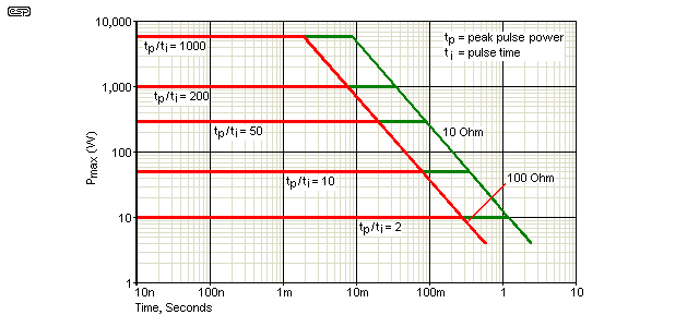
Figure 1 - 5W Pulse-Rated Resistor Dissipation Vs. Time
The above is an example, showing the allowable pulse power vs. time for a 10 ohm and 100 ohm 5W resistor. Predictably, lower values can handle a greater peak power because the wire is thicker. We are primarily interested in the 10ms rating, as this is close enough to the duration of the maximum first-cycle inrush current for a transformer. According to the chart, up to 300W is permissible, but the chart assumes repetitive pulses, so we can go somewhat higher. I wouldn't recommend that the worst case impulse power be any greater than 100 times the resistor rating. For a 5W resistor, that means the practical limit is 500W.
The allowable power is largely determined by the fusing limit of the resistance wire, and its thermal inertia. Thick wire has greater mass and therefore more thermal inertia, but the former and encapsulation also add to the total thermal inertia to some extent. Since these are generally ceramic they are primarily insulators, so they don't add as much thermal inertia as we might prefer. The resistance wire fusing limit depends on the material used. It's rarely specified, but nichrome (nickel/ chromium) alloy is popular as it has a fairly low thermal coefficient of resistance and can withstand very high temperatures (up to ~1,100°C).
Wirewound resistors are the only types that can normally withstand the very high pulse power needed for a soft start circuit. Most other resistors will simply vaporise the first time they are used. While the graph shows that lower values are more robust, a great many P39 boards have been built using 3 × 150 ohm resistors in parallel (or 3 × 33 ohm for 120V), and no failures have been reported after many years of service. You could use 3 × 15 ohms in series if it makes you feel any better, but the difference is minimal in real terms.
It's also important to ensure that PCB tracks are heavy enough to ensure they can handle the current without fusing. This is one of the advantages of using a soft-start circuit in the first place of course, because the very high inrush current is tamed by the circuit, and extraordinarily high peak current is avoided. This makes life easier for the power switch and everything else in the mains circuits. Instead of worst case 20-50A peak current, it can be limited to less than 5A.
"Shouldn't I use thermistors rather than resistors?" This is a common question, and while there are many caveats they will generally work well. Unfortunately, it can be very difficult for the novice (and not-so-novice) to determine the proper value and size, and manufacturers often don't help much. The specification format from one maker rarely matches that of another, and making direct comparisons can be difficult. Some quote a maximum current, others a rating in Joules, and some include almost nothing except the nominal resistance at 25°C and the dimensions - hardly helpful.
Many people like the idea of using NTC (negative temperature coefficient) thermistors for inrush limiting, with a common claim being that no additional circuitry is needed. For any product that does not draw consistent high power at all times, in a word, don't. Controversial? Not really - just because they are used by a number of major manufacturers doesn't always mean they'll be alright. If used in a switched system as described here, they are safe and reliable, but I have personally seen (yes, with my very own eyes) NTC thermistors explode mightily if there is a fault. Resistors can also fail, but the failure is (usually) contained - there are exceptions of course. In general, NTC thermistors are designed for very high peak current, but as noted earlier, you will see many different ways to describe the same thing, with almost no commonality between makers. To be genuinely useful, thermistors must be bypassed after the inrush event has ended.
If a bypass relay fails to operate because you used the amp's supply to activate the relay and a fault prevents the voltage from reaching its maximum, the thermistor will become a low resistance due to the current flow and the fuse will blow. However, if current is too high due to a major fault, the thermistor may explode before the fuse has a chance. I'm unsure why some people insist that the thermistor is 'better' than resistors - it isn't unless selected and used properly. In some cases may even be a less robust solution. As noted below, a resistor (or thermistor) value of about 50 ohms (230V) or 25 ohms (120V) is a pretty good overall compromise, and works perfectly with transformers up to about 500VA. The resistance should be reduced for power transformers over 1kVA.
If a thermistor is used, it needs to be sized appropriately. While some small thermistors may appear quite satisfactory, they will often be incapable of handling the maximum peak current. I suggest that you read the article on inrush protection circuits for more information. A suitably rated thermistor can be used in any version of this project (including the PCB based unit shown in Figure 2).
Under no circumstances will I ever suggest a thermistor without a bypass relay for power amplifiers, because their standby or low power current is generally insufficient to get the thermistor hot enough to reduce the resistance to a sensible value. You will therefore get power supply voltage modulation, with the thermistor constantly thermally cycling. This typically leads to reduced life for the thermistor, because the thermal cycling is the equivalent of an accelerated lifetime test regime (that's basically one of the tests that is done in the manufacturer's lab to find out how long they will last in use).
If there is enough continuous current (a Class-A amplifier for example), the surface temperature of any fully functioning thermistor is typically well over 100°C, so I consider bypassing mandatory to prevent excess unwanted heat. A bypass circuit also means that the thermistor is ready to protect against inrush current immediately after power is turned off, provided the equipment has been on for long enough for the thermistor to cool down of course. Without the bypass, you may have to wait 90 seconds or more before the thermistor has cooled if it's been operating at full temperature.
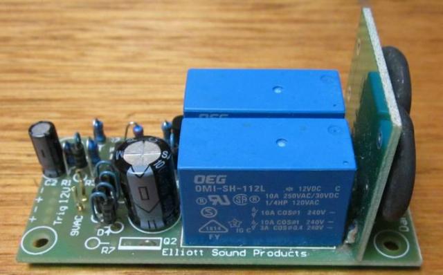
Figure 2 - Photo Of P39 Soft-Start PCB Using Thermistors
The photo above serves two purposes. It shows a completed P39 board, and includes suitable thermistors showing how they mount to the PCB, which needs an extra hole to wire the thermistors in series - this is easily drilled by the constructor. There are two 10 ohm thermistors, wired in series to give a total of 20 ohms. The relay bypasses the thermistors after about 100ms when power is applied, and this reduces the worst case inrush current to around 10A with 230V input. The total resistance includes the primary resistance of the transformer (3 ohms has been assumed in the calculation).
It is useful to look at the abridged specification for what might be considered a fairly typical NTC thermistor suitable for a power supply of around 150-300W depending on supply voltage (From Ametherm Inc. [ 1 ]). This is a 22mm diameter type, and for large transformers I suggest something around this size. NTC thermistors of about 10mm diameter are easier to install but cannot handle large energy 'surges'.
| Property | Value |
| Resistance | 20 ±25% Ohms |
| Max Steady State Current up to 25°C | 5 A |
| Max Recommended Energy | 125 J |
| Actual Energy Failure | 295 J |
| Max Capacitance at 120V AC | 7,600 µF |
| Max Capacitance at 240V AC | 1,800 µF |
| Resistance at 100% Current | 0.4 ohm |
| Resistance at 50% Current | 0.84 ohm |
| Body Temperature at Maximum Current | 178°C |
It is important to note that the resistance tolerance is very broad - this is common with all thermistors. Expecting close tolerance parts is not an option. The maximum capacitance values shown are for a traditional capacitor input filter following a bridge rectifier. Direct connection to mains is assumed. At rated current, the resistance is 0.34 ohm, so power dissipated is 1.36W which doesn't sound like much, but note the body temperature ... 178°C. I would suggest that optimum operation is at 1-2A continuous, where dissipation is reduced and the temperature will be lower.
The good part is that the surge energy is specified - in the above case it's 125 Joules. This means that it can withstand 125W for one second, or 1,250W for 100ms. It can also theoretically handle 12kW for 10ms or 120kW for 1ms, and unless stated otherwise this should not cause failure. Although there is some butt-covering with the maximum capacitance specification, this is largely a guide for the end-user. Based on this I'd suggest that 1kW for 100ms would be quite alright, as it's still only 100 Joules. Be warned though - there are probably as many ways of specifying thermistors as there are manufacturers, and not all provide information in a user friendly manner.
As noted above, thermistors should never be operated without a bypass relay. Even if the product draws a consistent power (sufficient to keep the thermistor hot), if there is a brief mains interruption, when power is restored the thermistor is already hot. It then achieves zero inrush limiting because the interruption has to last long enough for it to cool down to ambient temperature.
If multiple thermistors are used, they should be in series, not parallel. This is because the tolerance is so great that paralleled thermistors will not share the current equally, and it's even likely that only one will do anything useful, with the remainder serving no purpose. As the lowest resistance thermistor gets hot (because it takes most of the current), it will fall to a lower resistance and the other(s) won't do anything at all.
It can be helpful to know the basics of your transformer, especially the winding resistance. From this, you can work out the worst case inrush current. This table is shown in Transformers, Part 2 and is abridged here. Transformers with a winding resistance of more than 10 ohms (230V types) don't need a soft start circuit. Although the peak current can reach around 23A, that's well within the abilities of a slow blow fuse and normally never causes a problem. Of course, if you want to use a soft start on smaller transformers, there's no reason not to, other than the added cost.
| VA | Reg % | RpΩ - 230V | RpΩ - 120V | Diameter | Height | Mass (kg) |
| 160 | 9 | 10 - 13 | 2.9 - 3.4 | 105 | 42 | 1.50 |
| 225 | 8 | 6.9 - 8.1 | 1.9 - 2.2 | 112 | 47 | 1.90 |
| 300 | 7 | 4.6 - 5.4 | 1.3 - 1.5 | 115 | 58 | 2.25 |
| 500 | 6 | 2.4 - 2.8 | 0.65 - 0.77 | 136 | 60 | 3.50 |
| 625 | 5 | 1.6 - 1.9 | 0.44 - 0.52 | 142 | 68 | 4.30 |
| 800 | 5 | 1.3 - 1.5 | 0.35 - 0.41 | 162 | 60 | 5.10 |
| 1000 | 5 | 1.0 - 1.2 | 0.28 - 0.33 | 165 | 70 | 6.50 |
The (worst case) maximum inrush current is roughly the mains voltage divided by the winding resistance. There's a lot more detailed info on this (including more oscilloscope captures) in the Inrush Current article. It also includes waveforms with a rectifier followed by a large capacitance and a load, and will help you to understand the need for protection circuits with large transformers.
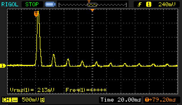
Figure 3 - Transformer Inrush Current
The above is an oscilloscope capture of the current in a 200 VA E-Core transformer when power is applied at the zero crossing of the mains waveform. This is the worst case, and can result in an initial current spike that is limited only by the winding and mains wiring resistance. The scale of the current monitor is 100mV/A, so the peak reading of 1.9V represents 19 amps. For a large toroidal, the peak current may exceed 150A. If the mains is applied at the peak of the AC waveform (325V in 230V AC countries, 170V where the mains is 120V), the peak inrush current for the same transformer is typically reduced to less than 1/4 of the worst case value ... 4.4A (both can be measured with good repeatability for the transformer tested).
As you can see, the inrush current is one polarity (it could be positive or negative), so superimposes a transient 'DC' event onto the mains. Other transformers that are already powered may also saturate (and often growl) during the inrush period. This is often known as 'sympathetic interaction'. To minimise the effects of inrush current and flow-on effects with other equipment, any toroidal transformer over 300VA should use a soft-start circuit such as that described in Project 39, or one of the alternative schemes described below. I consider 300VA to be borderline - a soft-start circuit isn't essential and it does add cost and complexity to a project, but the results are usually (just) acceptable if soft start isn't used with 300VA transformers.
Although the soft start circuit can be added to any sized transformer, the winding resistance of 300VA and smaller transformers is generally sufficient to prevent a massive surge current. Use of a soft start circuit is definitely recommended for 500VA and larger transformers. 300VA is borderline, and it's up to the constructor to decide whether s/he thinks it's necessary or not.
The worst case instantaneous current is limited only by the transformer's primary winding resistance and the effective resistance of the incoming mains supply (typically less than 1 ohm). For a 500VA transformer at 230V winding resistance will be in the order of 2.5 to 3 ohms, so the worst case current could easily exceed 70 amps. Even a slow-blow fuse is stressed by such a current surge, and that's why I am so adamant that soft-start is a really good idea.
As an example, a 500VA transformer is fairly typical of many high power domestic systems. Assuming an ideal load (which the rectifier and filter bank is not, but that's another story), the current drawn from the mains at full power is ...
I = VA / V (1) Where VA is the VA rating of the transformer, and V is the mains voltage used
Since I live in a 230V supply country I will use this for my calculations, but they are easy for anyone to do. Using equation 1, we will get the following full power current rating from the mains (neglecting the transformer winding resistance) ...
I = 500 / 230 = 2.2A (close enough)
At a limit of 200% of full power current, this is 4.4A AC. The effective series resistance needed to keep peak current to 4.4A or less is easily calculated using Ohm's law ...
R = V / I (2)
R = 230 / 4.4 = 52 Ohms (close enough)
Not really a standard value, but 3 × 150 Ohm 5W resistors in parallel will do just fine, giving a combined resistance of 50 Ohms. A single 47 ohm or 56 ohm resistor could be used, but you must check the datasheet to be sure the resistor you choose can handle the high instantaneous power. A 50W metal-clad resistor could be used. We don't need high power for normal use, but be aware that the instantaneous dissipation may be prolonged under certain fault conditions. Note that the RMS mains voltage was used, rather than the peak (325V), because the worst case current is not directly related to the peak voltage.
To determine the power rating for the ballast resistor, which is 200% of the transformer power rating at full power ...
P = V² / R (3)
For this resistance, this would seem to indicate that a 930W resistor is needed (based on the calculated 50 Ohms), a large and expensive component indeed. However, we need no such thing, since the resistor will be in circuit for a brief period - typically around 100-150ms, with the main current peak lasting only 10ms or so. The amp will (hopefully) not be expected to supply significant output power until stabilised. The absolute maximum current will only flow for 1 half-cycle, and diminishes rapidly after that (as seen in Figure 3). Refer to the pulse rating of a 5W resistor in Figure 1.
We need to be careful to ensure that the ballast resistor is capable of handling the inrush current. During testing, I managed to split a ceramic resistor in half because it could not take the current - this effect is sometimes referred to as 'Chenobyling', after the nuclear disaster in the USSR some years ago, and is best avoided. 
It is common for large professional power amps to use a 50W resistor, usually the chassis mounted aluminium bodied types, but these are expensive and may not be easy for most constructors to get. For the above example, 3 × 5W ceramic resistors in parallel (each resistor being between 150 and 180 Ohms) will give us what we want, and is comparatively cheap. If you haven't done so, read the section about resistors which has a lot of info about peak pulse current.
For US (and readers in other 120V countries), the optimum resistance works out to be 12 Ohms, so 3 × 33 Ohm 5W resistors should work fine (this gives 11 Ohms - close enough for this type of circuit).
It has been claimed that the resistance should normally be between 10 and 50 ohms (but with little or no reasoning), and that higher values should not be used. I shall leave this to the reader to decide. As always, this is a compromise situation, and different situations call for different approaches.
A 20 ohm resistor (or thermistor) is the absolute minimum I would use for 230V, and it needs to be selected with care. The surge current is likely to demolish lesser resistors, especially with a 230V supply. While it is true that as resistance is reduced, the resistance wire is thicker and more tolerant of overload, worst case instantaneous current with 20 ohms is 11.5A at 230V. This is an instantaneous dissipation of 2,645W (ignoring other resistances in the circuit), and it will require an extremely robust resistor to withstand this even for short periods. For 120V operation with 20 ohms, the peak current will only be 6A, reducing the peak dissipation to 720W.
In reality, the worst case peak current will never be reached, since there is the transformer winding resistance and mains impedance to be taken into account. On this basis, a reasonable compromise limiting resistor (and the values that I use) will be in the order of 50 Ohms for 230V (3 × 150 ohm/ 5W), or 11 Ohms (3 × 33 ohm/ 5W) for 120V operation. Resistors are wired in parallel. You may decide to use these values rather than calculate the value from the equations above, and it will be found that this will work well in nearly all cases, but will still allow the fuse to blow in case of a fault. These values are suitable for transformers up to 500VA, although they'll most likely be alright for larger units as well.
This is in contrast to the use of higher values, where the fuse will (in all probability) not blow until the relay closes. Although the time period is short, the resistors will get very hot, very quickly. Thermistors may be helpful, because as they get hot their resistance falls, and if suitably rated they will simply fall to a low enough resistance to cause the fuse to blow.
Another reason you may need to use a lower value is that some amplifiers have a turn-on behaviour that may cause a relatively heavy current to be drawn from switch-on. These amplifiers may not reach a stable operating point with a high value resistance in series, and may cause misbehaviour until full voltage is applied. If your amplifier exhibits this behaviour, then the lower value limiting resistors must be used.
If flaky mains are a 'feature' where you live, then I would suggest that you may need to set up a system where the amplifier is switched off if the mains fails for more than a few cycles at a time. The AC supply to a toroidal transformer only has to 'go missing' for a few cycles to cause a substantial inrush current, so care is needed.
If a thermistor is used, I suggest a robust version, rated for a comparatively high maximum current. 22mm diameter devices are generally rated for much higher currents than you are likely to need, so will suffer minimal thermal cycling. A nice round value is 10 ohms at 25°C - this does mean higher peak currents than I suggest above, but you can always use two or three in series - especially for 230V operation. 2 × 10 ohm thermistors in series gives a very high surge rating (measured in Joules), and limits the peak inrush current to around 12A with a 500VA transformer.
Some large professional amps use a TRIAC (bilateral silicon controlled rectifier) to bypass the soft-start resistor/ thermistor, but I prefer to use a relay for a number of very good reasons ...
They will also cause their share of problems, but these are easily addressed. The worst is providing a suitable coil voltage, allowing commonly available devices to be used in power amps of all sizes and supply voltages. Because relays are still so popular, they are easy to get in most common coil voltage (e.g. 5V, 12V, 24V, etc.).

Figure 4 - Soft-Start Resistors and Relay Contacts
Figure 4 shows how the resistors are connected in series with the supply to the transformer, with the relay contacts short circuiting the resistors when the relay is activated. This circuitry is all at the mains voltage, and must be treated with great respect.
'A' represents the Active (Live or Hot) lead from the mains switch, and 'SA' is the switched Active, and connects to the main power transformer. Do not disconnect or bypass any existing wiring, simply place the resistor pack in series with the existing transformer.
Do not attempt any wiring unless the mains lead is disconnected, and all connections must be made so that accidental contact to finger or chassis is not possible under any circumstance. The resistors may be mounted using an aluminium bracket that shrouds the connections preventing contact. All leads should be kept a safe distance from the chassis and shroud - where this seems impossible, use insulation to prevent any possibility of contact. Construction notes are shown later in this project. The safety aspect of these circuits cannot be stressed highly enough !
The relay contacts must be rated for the full mains voltage, and at least the full power current of the amplifier. The use of a relay with at least 10A contact rating is strongly recommended.
HINT: You can also add a second relay to mute the input until full power is applied. I shall leave it to you to make the necessary adjustments. You will have to add the current for the two relays together, or use separate supply feeds if utilising the existing internal power supply voltage.
Control circuits range from very simple (and often rather ill-conceived) to quite complex. Ultimately, the circuitry depends on whether the designer has considered everything, or has looked only at a solution that creates a reasonably consistent delay when power is turned on. Many fail to ensure that the circuitry resets itself quickly, so a rapid on-off-on cycle (whether by design or accident) provides protection after a brief interruption. In general, any circuit that does not reset in under 500ms should be considered a fail. A full reset ensures that when the power is restored (after perhaps 1/2 second or so), the ballast resistors are in circuit again, and the soft start is performed just as it would if the equipment were turned on after being turned off overnight.
The least desirable way to power the control circuit is from the transformer's secondary. If there is a major fault, the secondary voltage won't rise to its maximum and the control circuit may never operate. While this is not a common failure, it's well within the bounds of possibility. In the case of amplifiers (or other equipment) that expect significant current from the moment of switch-on, the ballast resistors may have sufficient resistance to prevent normal start-up, and they will be fried.
The text for Project 39 recommends that an auxiliary transformer be used, and this is by far the safest way to do it. This allows for the control circuitry to operate at low voltage, isolated from the mains. It's safe to work on, take measurements or even look at waveforms with an oscilloscope.
If an independent 12V supply were to be available in all power amps, supplying power would be very simple. Unfortunately this is rarely the case. Most amps will have DC supplies ranging from ±25V to about ±70V, and attempts to obtain relays for odd voltages will be met with failure. Relay coils are typically rated for 5V, 12V, 24V and 48V as well as 120/ 230V AC, but AC relays are definitely not recommended. However, even if you do have a transformer with an auxiliary winding, if the secondary load is great enough the auxiliary winding won't come up to normal voltage either.
An auxiliary supply means the addition of a second transformer, which may sometimes be difficult due to space limitations. It is still the safest way to go, and a control circuit using this approach is shown in Figure 2. This is the simplest to implement, but some may consider the added cost of the second transformer hard to justify. IMO it's not an issue, and is by far the preferred option. It's pretty much mandatory for Class-A amps. There's another advantage too. The small transformer can be left on all the time, and the mains is then turned on and off by switching the 9V AC to the soft start board (which would use a second relay to switch the power on and off). Again, this is the approach taken with Project 39, and it ensures that mains wiring can be restricted to its own corner of the chassis, and everything else is low (relatively) voltage.
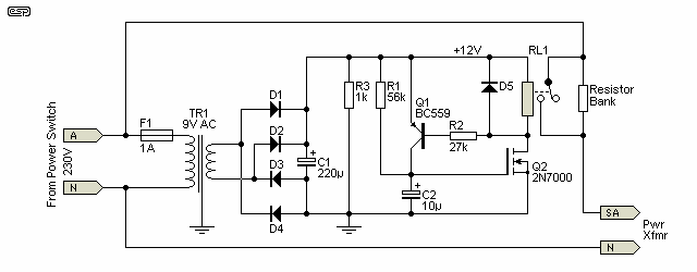
Figure 5 - Auxiliary Transformer Control Circuit
This uses simple bridge rectifier, and a small but adequate capacitor. The control circuit uses readily available and low cost components, and can easily be built on Veroboard or similar. All diodes can be 1N4004 or equivalent. Use a transformer with a 9V AC secondary, which will supply close enough to 12 Volts for this circuit. No regulation is needed, and the controller is a simple timer, activating the relay after about 100ms. I have chosen a MOSFET for the switch, since it has a defined turn-on voltage, and requires virtually no gate current. With the component values shown, the relay will activate in about 100 milli-seconds. This can be increased (or decreased) by increasing (decreasing) the value of R1 (27k). The transformer need only be a small one, since current is less than 100mA.
Note Carefully: The value shown for R1 (56k) may need to be varied to obtain the required time delay of around 150ms. The actual value needed depends on the switching threshold for the MOSFET and the value of C2, which is an electrolytic cap and they have a wide tolerance. In general, expect the value to be somewhere between 27k and 68k, but in some cases you may need more or less than the range given.
The MOSFET (Q2 - 2N7000) has a gate threshold voltage that is quoted as being between 0.8V to 3V, with 2.1V given as the 'typical' value. As a result, you will need to adjust the value of R1 to obtain the correct delay. You could use a 100k trimpot if you like - that should cover most eventualities. If the threshold is 0.8V (I've not seen one that low), the timer will only run for about 30ms, so R1 would need to be increased to about 82k. At the high end (3V), R1 needs to be reduced to about 22k for a 100ms delay. Note that the PCB version uses an opamp comparator, so the timing is very predictable.
Q1 is used to ensure that power is applied to the relay quickly. When a voltage of 0.65V is sensed across the relay, Q1 turns on, and instantly completes the charging of C2. Without the 'snap action', the circuit will be sluggish, and may not activate the relay with 100% reliability. The circuit's reset time is under 120ms with the values shown, and this will usually be acceptable.
NOTE: C1 should be rated for a ripple current of at least 700mA to prevent capacitor heating. The actual ripple current should be around 85mA with the circuit as shown. Be warned that if the cap gets warm (or hot), then its reliability and longevity will be compromised.
It is possible to make the relay release much faster, but at the expense of circuit complexity. A simple logic system could ensure that the circuit was reset with a single AC cycle dropout, but this would be too fast for normal use, and quite unnecessary. C1 may have to be changed based on the relay (The test relay has a 270 ohm coil resistance). If the value is too small, the relay may chatter or at least buzz, and will probably overheat as well, due to eddy currents in the solid core used in DC relays. The capacitor should be selected based on the value that makes the relay quiet, but still releases quickly enough to prevent high inrush current if there is a momentary interruption to the mains supply. The value shown (220µF) will generally be suitable for most applications. If you use a 470µF cap, the release time is extended to about 250ms - not too bad, but slower than it should be.
Where it is not possible to use the transformer for any reason, then the circuit in Figure 5 can be used. This uses a capacitor to drop the mains voltage for the circuit, and it's necessary to use a 24V relay to minimise the current drawn. While a 12V relay can be used, the capacitor (C1) would have to be larger and more expensive. Note that C1 must be a mains rated X2 type. R3 and R4 ensure the cap discharges when mains is disconnected to reduce the risk of electric shock. Two are used in series to obtain a satisfactory voltage rating. If used for 120V operation, C1 needs to be 2 × 470nF caps in parallel or the supply voltage will never get to 24V and the relay may not operate.
WARNING - All circuitry is at full mains potential, and it must be enclosed to prevent accidental contact!
A 1W resistor (R5) is used to limit inrush current into the X2 input capacitor. Where possible, I always recommend that any resistor that dissipates significant power (or has a high surge current) be at least double the expected power dissipation to ensure long life and cooler operation, although this obviously cannot apply to the main inrush limiting resistors. The 24V zener diode ensures that the voltage is limited if you decide you need a long delay. Without it, the voltage across C2 can reach a dangerous level with a long delay time because no current is drawn from the rectifier. Note that C2 should be rated for no less than 35V, but C3 can be a 16V type if available (most small electros are rated for at least 25V).
C1 must be a Class-X2 AC rated capacitor. Never use DC caps (regardless of voltage rating), as they are not designed to handle large AC voltage across them. While it is possible to use a 630V DC cap with 120V mains, it's still a very bad idea and may lead to capacitor failure. DC caps at 230V are never acceptable. X2 caps are rated to handle 275V AC applied directly across the cap, and they are the only ones that will be approved anywhere (including most 120V countries). The diodes can be 1N4001 types, because they will never have a reverse voltage of more than 30V.
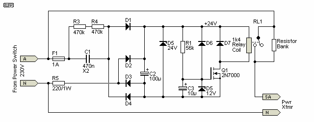
Figure 6 - 'Off Line' Control Circuit
With the timing values shown (56k and 10µF), the delay time is about 130ms (as simulated), but this depends on the MOSFET's threshold voltage and the time it takes to charge C2. The simulator's 2N7000 MOSFET has a threshold of 2.8V, but it varies widely in real parts. MOSFETs have a very wide parameter spread, and the datasheet claims the threshold can be from 800mV to 3V. You will need to adjust the value of R1 to obtain the required delay. Note that the fuse shown is only for the soft-start power supply, and a separate fuse is needed for the transformer that's being powered.
After power is removed, ideally the relay will drop out immediately, but this won't happen in practice. If C2 does not discharge fully, and there may be enough residual voltage to re-energise the relay in the case of a short mains drop-out. This is inevitably a compromise though, and to be 100% effective the circuit really needs to have a dedicated discharge system. This makes a simple circuit much more complex. As shown, the circuit will reset (ready for the next soft-start) in under 400ms, but beware! Many relay datasheets indicate that the 'must release' voltage is around 10% of the rated voltage, so a 24V relay cannot be guaranteed to release until the coil voltage has fallen to 2.4V. While most will (probably) release at a higher voltage, unless you run tests you'll never know for certain.
I tested a couple of common 24V relays for pull-in and drop-out voltages. These relays have a 1.5k coil, and both pulled in at around 15V. One released reliably at 10V, but the other one I checked remained energised until the coil voltage was around 5V. This shows that they are variable, and it's worthwhile running some tests so you know exactly what you have to deal with.
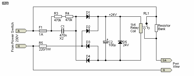
Figure 6A - Simplified 'Off Line' Control Circuit
The circuit in Figure 6A is simplified even further, and variations of the theme are all over the Net. It relies only on the value of C2 for timing, and the relay coil gets a (relatively) slow voltage rise. Should C2 degrade (because it's next to the resistor bank for example), the timing will reduce as the capacitance reduces with age. The coil resistance of the relay you use is fairly critical. The resistance should not be less than 1k or either power supply won't be able to provide the necessary current. Many 24V relays have a coil resistance of 1.4k or more.
Any transformerless design involves multiple compromises, and the circuits shown are no different. Because of the capacitor feed (C1), the voltage rises relatively slowly. It takes around 120ms to reach 24V with 230V/ 50Hz mains, and about 90ms for 120V/ 60Hz with double the capacitance. Consequently, it is not possible to have the soft-start delay any less than this unless you can accept very high ripple on the 24V DC line. The circuit using an auxiliary transformer has no such limitation, as full voltage is reached after only a couple of mains cycles (~40ms at 50Hz, or 33ms at 60Hz).
The Figure 6/ 6A circuits are just two ways it can be done, but there are other possibilities of varying complexity. It's not feasible to show them all, and especially those that you may find elsewhere, some of which are a disaster waiting to happen. There are many I've seen on the Net that are definitely in the latter category - while they will (probably) all work when power is first applied, many (most?) have no provision to ensure that the storage cap is discharged, and it may take several minutes (or sometimes a great deal longer) after power-off before the circuit will actually provide soft start again. The idea of ensuring a quick reset doesn't appear to have been considered, so they are no more useful than a hot thermistor.
Any soft-start circuit that does not provide a reset time of less than 1 second is a liability, and should not be used. Ideally, the system would reset instantly, but this is unrealistic. In (what's laughingly known as) the real world, we should aim for a reset time of no more than perhaps 150ms, with 500ms being the (just tolerable) upper limit. It's not an easy compromise to get reliable delay and a fast reset in a simple circuit.
A technique that's starting to make inroads in switchmode supplies intended for high power LED lighting is an active limiter. Using a MOSFET, it's possible to turn on the power in a controlled manner so that instead of the voltage being applied instantly (either through a limiting circuit or directly), it's increased from zero to maximum over perhaps 10-20 mains cycles. This approach ensures close to zero transformer inrush, and limits the capacitor charge current. It's fairly cheap and easy to add to an existing SMPS design, because the diode bridge already exists, and it's a complete system in a (usually) potted module so only needs a few support parts to implement.
To do this in a stand-alone inrush limiter is tricky, and not inexpensive to achieve. The MOSFET and associated bridge rectifier (so it can operate with AC) must be bypassed after a preset time has elapsed to minimise dissipation, but as a form of inrush limiting it's probably as good as you will ever get. Depending on the load, short term MOSFET dissipation may be quite high, and at least a small heatsink is going to be required. The circuitry isn't especially difficult, but there may be a fairly long time before the MOSFET starts to conduct - it could be 1-2 seconds, depending on the MOSFET itself. Because MOSFETs have a wide parameter spread, the circuit either needs to be 'self-compensating', or an adjustment would be needed to set the operating points between the start of conduction and full conduction.
The trace in Figure 8 shows what the input current waveform might look like, with a full wave rectifier and 10,000µF filter cap at the transformer's output as shown next. A 45W load is in parallel with the filter cap. This is conceptual, in that it has been simulated but not built, although I have used a Variac (spun up to full voltage quickly) to prove that inrush current is minimal or non-existent when the mains is ramped up. The exact mechanism for doing so is immaterial, provided the voltage across the transformer rises smoothly over a reasonable time period (around 10 to 20 mains cycles seems to be a fair compromise). While a Variac is ideal, it's probably a tad too large (and expensive) to use one as a soft start in an amplifier.
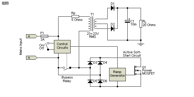
Figure 7 - Simplified Linear Soft-Start Using MOSFET
The circuit uses Q1 (MOSFET) to gradually increase the voltage applied to the transformer over a period of around 500ms. Diodes D3-D6 are used to ensure that the MOSFET gets DC rather than AC, and need to be rated for enough current to get the circuit started. T1 is the controlled mains transformer, with Rp being the winding resistance. The control circuits are responsible for providing an isolated supply for the ramp generator and activation of the bypass relay. In a complete system, there would also be current monitoring to detect fault conditions before any circuit damage can occur.
D1-D2 is the main rectifier, C1 (10,000µF) is the filter cap, and RL is a 20 ohm load. The transformer was arbitrarily set for 10:1 transformation ratio, so the AC output is 23+23V RMS with 230V mains. Unfortunately, it's not possible to simulate saturation in the simulator I use, but it will show the input current offset from zero at turn-on (assuming worst case turn-on at the mains zero crossing). This is a very clear indicator that saturation will occur in a 'real' transformer.
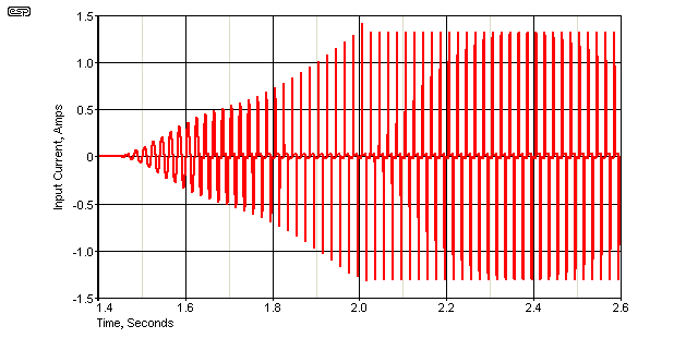
Figure 8 - MOSFET Soft-Start Input Current
The input current simply ramps up to its maximum value as set by the load resistor, with no surges and no opportunity for transformer saturation. The relay closes at 2 seconds (not that you'd really notice), and the waveform is shown from 1.4 seconds because that's how long it took before the MOSFET started to conduct with the simple ramp generator I used. With the circuit shown, the peak MOSFET dissipation is 63W at 1.6 seconds. Average dissipation over the MOSFET conduction period is around 25W for a period of just over 500ms. While you may think that a small TO-220 MOSFET would be alright, you will almost certainly need something that's much more rugged.
I've also run a bench test using a Variac turned up as quickly as possible from zero to maximum, and transformer saturation was never seen to exceed about double the normal idle current. This is a good result, but when dedicated circuitry is added to make the MOSFET do the same thing, it will be quite complex and fairly costly to implement.
The waveform is very distorted because the load is nonlinear. At the beginning, the current waveform into the transformer is (kind of) a square wave due to the MOSFET's conduction characteristics, but the transformer doesn't care about that. There can be no doubt that a fully developed circuit using this principle is as good as you will ever get, but of course it comes down to the space needed and the final cost. There's also the matter of need. Unless the application is critical, there is unlikely to be any requirement for anything more advanced than the circuits shown earlier, with a resistor (or thermistor) bypassed by a relay after around 150ms or so. It's a well used technique that works well and is fairly inexpensive.
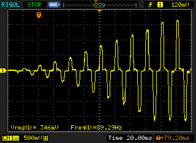
Figure 9 - Ramped Variac Soft-Start Input Current
So, while I didn't build a MOSFET version, I did use my Variac to ramp up the voltage. The load was a 10,000µF cap with 16 ohms in parallel, with the same transformer used for the other bench tests. The result is shown above, and is almost perfect turn-on behaviour. I managed to get the Variac from zero to 90% of full voltage within 11 mains cycles, and the mains input current is shown. It has the same distortion characteristics as seen in the simulation, and the peak input current doesn't exceed 1.7 amps. Full load peak current is expected to be about 575mA RMS with this circuit, with the peak value being around 1.8A according to the simulator. When I ran a new simulation (using the Figure 7 circuit) and substituting the 'real' transformer ratios for the previously simulated version, I obtained almost identical figures to those I measured on the test bench. This is a 'text-book' result in all respects, with a simulation and 'real life' in almost perfect agreement (although the scope did get confused measuring the frequency).
Turning off a MOSFET based circuit may introduce a small problem. The MOSFET will be rather annoyed if the mains is turned off and there's an inductive kick-back from the transformer. The easiest way to fix that issue is to use a MOSFET that is avalanche rated, meaning it is designed to accept an over-voltage condition and uses controlled breakdown to dissipate the back-EMF. If carefully selected, avalanche rated power MOSFETs will happily survive the turn-off transients likely to be found with most transformers. During power-off, the bypass relay must also be turned off. If it is turned off first, the MOSFET breaks the current and an arc cannot be created, resulting in (electrically) noise-free switching.
We aren't out of options yet. You will recall from earlier in this article that if power is applied to a transformer at the maximum peak of the AC waveform, inrush is minimised. If a peak detector circuit is used, it's not especially difficult to trigger a TRIAC to turn on the power at the AC peak, with a relay taking over as quickly thereafter as possible. Nonlinear loads can cause serious problems for TRIAC and SCR circuits, but are perfect for a fast turn-on at a specific time.
While this technique will work well for a transformer, it's the opposite of what we need for a capacitor bank. However, in normal use we expect that there will be some transformer saturation, and that can be used to our advantage. As shown in the Inrush Current article, a transformer that draws 18A or more if switched on at the zero crossing only draws around 4A (peak) when switched on at the AC peak. This small amount of saturation may be enough to limit the peak current drawn by the filter cap(s) after the rectifier.
If we compare the peak switched transformer inrush with a resistor based soft start, the current is actually a little lower than we'd get by using a 50 ohm resistor. We still need to consider the filter caps of course, but the combination of saturation plus a capacitor load cannot be simulated, so I built and tested a peak switched circuit so I could measure the results. I used my inrush tester to turn the main on at the peak of the mains waveform. While you can (at least in theory) get peak switching SSRs that contain the necessary circuitry to reliably trigger at the mains peak, for the most part you'll have to make your own because they don't appear to be available from the usual outlets.
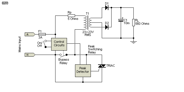
Figure 10 - Peak Switching Circuit (With Bypass Relay)
The control circuitry is used to turn on the TRIAC, which uses a peak detector to ensure that the switching is really at the peak. A bypass relay shorts out the TRIAC a few milliseconds later. At power-off, the bypass relay should release first, and the mains will turn off as the current passes through zero. No further details are provided, but a complete circuit for a peak switching relay might be made available as a project if there's enough interest. The above is the actual circuit of the arrangement I bench tested.
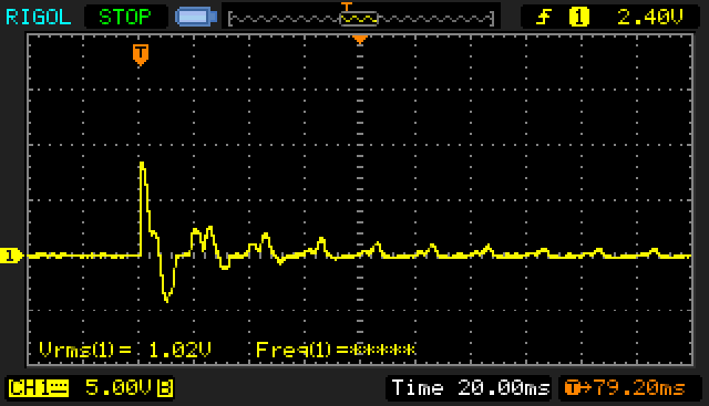
Figure 11 - Peak Switching Input Current With Capacitor Load
The waveform above shows the peak current to be 8.5A, when turned on at the mains peak into a fully discharged 10,000µF capacitor. This used the same transformer used for the waveform shown in Figures 3 and 9, but switched at the mains peak. The scale is 1V/A, so the peak reading of 8.5V indicates 8.5 amps. While there is certainly a high initial current, it's quite brief (about 5ms) and it's apparent that there is little effect from core saturation. Without the capacitor load, the peak input current is around 4A due to saturation (switching on at the waveform peak minimises but does not eliminate saturation).
An additional option would seem (at least until you see the results) to use a modified dimmer circuit (which must be a leading-edge type). When power is applied, the voltage is ramped up from zero to the maximum, using phase control and a TRIAC dimmer. It's imperative that the dimmer is bypassed as soon as the inrush period is finished, or erratic triggering and/or electrical noise is probable - even with a dedicated 3-wire dimmer (such as that shown in Project 159). The reason is that the TRIAC cannot trigger if it has no current, and the mains input waveform is anything but friendly with a capacitor input filter as used in 99.9% of hobbyist projects (and a great many commercial products as well).
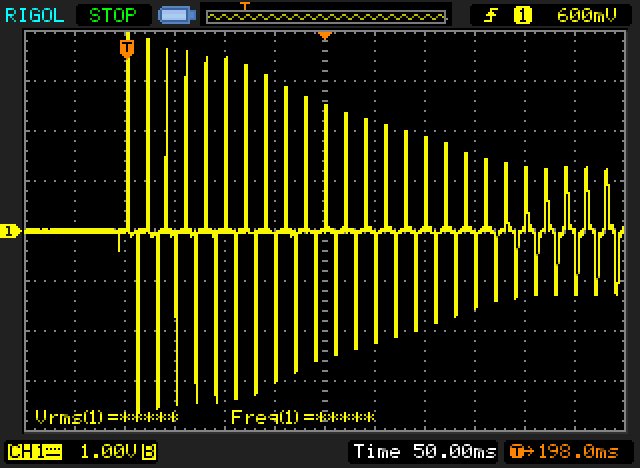
Figure 12 - Input Current With Dimmer And Capacitor Load
At first thought, this seems sensible and logical, but the reality is rather different. The waveform above shows what happens. There's no inrush current as such, but the rapid turn-on of a TRIAC causes the peak current to reach a fairly silly level until the dimmer is fully on. The average current is quite low (it's difficult to see on the scope trace because I wanted to show the complete process, from zero to maximum). Peak current is 4A, but the pulse duration is short. At low dimmer settings, the conduction period may only be a millisecond or two, which can't be seen properly on the trace. As the dimmer setting is increased, the peak current falls until it's more-or-less back to normal.
Compared to the Variac (or a linear MOSFET circuit) it's pretty ugly, and the transformer buzzes as the voltage passes through the halfway point. Although it's not a pretty sight, as an inrush limiter it does work - we are aiming to maintain a low input current, and that is achieved. When the circuit triggers at a low voltage (late in each AC cycle), the RMS current can be as low as 400mA, despite the high peak current. While it remains an option, it isn't one that I'd ever use in any equipment. However, TRIAC 'dimmer' circuits have been used in front of transformers as pre-regulators, and the technique was even used in a commercial power amplifier to modulate the supply voltage along with the signal level.
Class-A power amps and some other loads will impose a heavy load on the transformer from the instant of turn-on. Any soft-start for this type of load needs to be carefully analysed to ensure that the inrush is limited, and that the circuit powers up normally. Some may not, and if you are unsure then you need to test carefully to make absolutely certain that no hazard is created.
NOTE: I strongly suggest that the auxiliary transformer or off-line transformerless power supply method is used with a Class-A amp, as this will eliminate any possibility of relay malfunction due to supply voltages not being high enough with the ballast resistors in circuit.
Because of the fact that a Class-A amp runs at full power all the time, if using the existing supply (from the secondary) you must not go below the 200% suggested inrush current limit. In some cases, it will be found that even then there is not enough voltage to operate the relay with the input ballast resistors in circuit.
If this is found to be the case, you cannot use this method, or will have to settle for an inrush of perhaps 3-5 times the normal full power rating. This is still considerably less than that otherwise experienced, and will help prolong the life of the supply components, but is less satisfactory. The calculations are made in the same way as above, but some testing is needed to ensure that the relay operates reliably every time. See note, above.
Electrical safety is paramount with circuits such as these. There are no suggested methods for mounting the input ballast resistors, as it depends on many factors. As already noted, high power NTC thermistors are a good idea, and because they are designed for this very application you can be fairly certain of success. They will cool down as soon as the relay operates, so are ready for use again quite quickly.
Make sure that your wiring ensures that there is a minimum of 5mm creepage and clearance maintained between low voltage and 'hazardous voltage' (mains) when the resistors are mounted. If there's space available, more creepage and clearance does no harm, and helps ensure that electrical safety barriers are unlikely to be breached (by internal debris as the result of a capacitor exploding for example - and yes, that can and does happen).
For anyone who doesn't know the terms, 'creepage' distance is the physical separation distance across a surface (such as PCB laminate or other insulating material), and 'clearance' is the physical distance in air or 'free space'. Clearance distances can be extended by using insulating material (so become subject to creepage requirements). Any insulating material should be non-flammable if there is any likelihood of very hot parts that may cause fire. Local regulations usually dictate what is/ is not suitable, and the dielectric strength of the material used must be such that it will not suffer electrical breakdown in use.
An alternative is to obtain a bolt-down aluminium bodied resistor. This should be selected for the desired maximum inrush current, and will be rated for a minimum of around 25W and with an adequate surge current rating. Great care is absolutely necessary, because although resistors or thermistors are only in circuit for 100 milliseconds, a fault can create a disaster. Since the resistors will get extremely hot if there's a fault and the bypass relay doesn't activate, simply wrapping them in heatshrink tubing (for example) will do no good at all because it will melt. The idea is to prevent excessive external temperatures until the resistors (hopefully) fail and go open circuit. The method used with the P39 PCB is simpler again - 3 x 5W resistors are mounted on an auxiliary circuit board, and the leads should be kinked to ensure that the resistors can't fall out even if the solder melts. I have yet to see or hear of a resistor failure, or more importantly any electrical safety hazard.
The relay wiring is not critical, but make sure that there is a minimum of 5mm between the mains contacts and any other part of the circuitry if you use an auxiliary transformer. Mains rated cable must be used for all power wiring, and connections must be protected against accidental contact. Keep as much separation as possible between any mains wiring and low voltage or signal wiring.
The connections to the ballast resistors are especially important. Since these may get very hot if the relay fails to operate, care must be taken that the lead will not become disconnected if the solder melts, and that there is sufficient solder to hold everything together and no more. A solder droop could cause a short to chassis, placing you or other users at great risk of electrocution. An alternative is to use a screw-down connector, which must be capable of withstanding high temperature without the body melting. Ceramic screw terminals are available, and they will survive most overheating 'events' without failure.
Do not use heatshrink tubing as insulation for the incoming power leads to the ballast resistors. Fibreglass or silicone rubber tube is available from electrical suppliers, and is intended for high temperature operation. If you wish to experiment with an active soft-start circuit, it's entirely up to you to ensure that it is safe and reliable. No circuit details are given here, and it's unlikely that I will look into this any further as it's too complex for what is normally a fairly simple task. We aren't after perfection, just a straightforward way to connect a transformer to the mains, without a huge inrush current.
In case you missed this the first time: In the event of an amplifier fault or continuously heavy current drain at power-on, the fuse may not blow (or at least, may not blow quickly enough to prevent damage) with a circuit powered from the secondary, since there may not be enough power to operate the relay. If you don't like this idea - USE THE AUXILIARY TRANSFORMER. The fuse might only blow after the relay closes, but at least it will blow. 100ms is not too long to wait.
These circuits are designed to limit the maximum current at power on. If there is no power to operate the relay, the ballast resistors will absorb the full mains voltage, so the resistor example described above will dissipate over 900W! The resistors will fail, but how long will they last? The answer to this is a complete unknown (but 'not long' is a good guess). Thermistors may or may not survive.
The reliability of the relay circuit is paramount. If it fails, the ballast resistor dissipation will be very high, and it will overheat, possibly causing damage. The worst thing that can happen is that the solder joints to the resistors will melt, allowing the mains lead to become disconnected and short to the chassis. Alternatively, the solder may droop, and cause a short circuit. If you are lucky, the ballast resistors will fail before a full scale meltdown occurs.
Make sure that the mains connections to the resistors are made as described above (Construction Notes) to avoid any of the very dangerous possibilities. You may need to consult the local regulations in your country for wiring safety to ensure that all legalities are accounted for. If you build a circuit that fails and kills someone, guess who is liable? You!
It is possible to use a thermal switch mounted on the resistors to disconnect power if the temperature exceeds a set limit. These devices are available as spare parts for various household appliances, or you may be able to get them from your normal supplier. Although this may appear to be a desirable option, it is probable that the resistors will fail before the thermal switch can operate.
WARNING: The small metal bullet shaped non-resetting thermal fuses have a live case (it is connected to one of the input leads). Use this type with great caution !! Also, be aware that you cannot solder these devices. If you do, the heat from soldering will melt the wax inside the thermal fuse and it will be open circuit. Connections should use crimped or screw terminals.
Several circuits or circuit ideas have been presented here, and it's up to you which technique you use. An off-line (transformerless power supply) circuit is not a bad idea, but it may be difficult to ensure that all live wiring is properly protected from accidental contact. Since it's an entire circuit board, this can be quite difficult to achieve. Active inrush limiters have similar requirements, with much of the circuitry at mains potential. While everything can be installed in a plastic box, that could become a fire hazard if there's a catastrophic fault. A metal box solves that issue, but then the contents have to be properly insulated (with high temperature, non-flammable materials) and the box earthed for safety.
Main Index
Articles Index
