
 |
| Elliott Sound Products | 6dB/ Octave Passive Crossovers |
 Main Index
 Articles Index
 Speaker crossover networks are always a requirement with any system using two or more loudspeaker drivers. The Design of Passive Crossovers article covers 12dB/ octave types in considerable detail, and shows just how complex it is to get a good result. While some high quality systems go to great lengths to get everything right, many don't, so the result is not always as expected (or hoped for). There is also some information on 6dB/ octave crossovers, but in many circles they have a bad reputation.
Some designers carry out a process called 'voicing', where the design is tweaked to get it to sound 'right'. Whether this is backed up with detailed measurements and/ or analysis depends on the designer. For simple, 2-way passive crossovers that are intended for low power (no more than 30W/ channel or so) it's very hard to make a case against a 6dB/ octave (first order) crossover, and it should be used in a serial network rather than parallel. While one could be forgiven in thinking that the two are equivalent, this only applies if the loads (the drivers) are perfectly resistive. This doesn't happen with any real-world loudspeakers.
The differences aren't subtle looking at the electrical performance, but may be less noticeable in listening tests. The nice thing about the series network is that it is 'self-correcting', and will always sum flat electrically. Whether or not this translates to the acoustic response is another matter, but in general it works out well. This is covered in some detail in the article Series vs. Parallel Crossover Networks, but the explanations there look at both first and second order systems, and it is not intended as a design guide.
My preference is for active crossovers, but for a simple system this is difficult to justify. The cost penalty isn't great, but it adds complexity and means a four-wire connection is needed for the speaker. This isn't sensible for a simple 2-way box that's used at low power. An example of just such a system is shown in Project 73 (Hi-Fi PC Speaker System), and that shows a series network. This has been in daily use for nineteen years (at the time of publication of this article), and has seen several different PCs in its time. Apart from one repair (a faulty electrolytic capacitor in the power supply), the system hasn't missed a beat in all that time!
It's worth noting that the first-order (6dB/ octave) crossover is the only version that works best when connected as a serial network. Higher order crossovers become unwieldy and very sensitive to component variations, including voicecoil resistance. This is covered in some detail in the ESP article referenced above, and serial connection is not recommended for 12dB/ octave or above. As part of my workshop monitoring system, I use a simple vented 2-way box with a series 6dB/ octave crossover. It doesn't match my horn-loaded 'main' system (fully active), but it does let me make direct comparisons of power amplifiers, and it sounds fairly good overall.
This article has many similarities with the Series vs. Parallel Crossover Networks article, but is specifically aimed at first order systems, and provides better graphs to show the results of the simulations. This is more of a construction guide, with emphasis on loudspeaker driver impedance compensation networks. These are essential for a parallel configuration, and optional for a series connected crossover network.
With higher order crossovers (12dB/ octave or 18dB/ octave) impedance compensation is mandatory if you want a final system that performs well. In many cases this point is not made clear (or may not even be mentioned!). If you expect to build a fully compensated 3-way crossover (12dB or 18dB/ octave), be prepared for a world of pain - these networks become very complex, very quickly. The cost is likely to be such that using an active system (provided you build your own active crossovers and amplifiers) will be cheaper and will perform far better. This is especially true if you intend to use 4th order (24dB/ octave) filters. Not only are you up for the cost of eight expensive inductors and capacitors (just for the crossover!) the circuit sensitivity to any variation is high, and impedance compensation still can't cope with voicecoil temperature changes.
To build any speaker system you need to be able to measure the Thiele-Small parameters. This can be done in a number of ways, and you can use the technique described in the article Measuring Loudspeaker Parameters. These parameters are essential to obtain the optimum enclosure volume and vent dimensions, but are not necessary for the tweeter. You can measure the tweeter if you wish, but there's no point trying to obtain Vas (equivalent air volume of suspension) as it's not useful for anything. You can easily measure the main characteristics, namely ...
fs Resonant frequency Le Voicecoil Inductance Re Voicecoil resistance Zmax Maximum impedance Qms Mechanical Q Qes Electrical Q Qts Total Q VAS Air Volume For Equivalent Compliance
These parameters can be used to calculate the equivalent circuit of the driver, both for the woofer/ mid-bass and the tweeter. These are necessary only if you wish to devise impedance correction networks. Although the calculations that follow used a hypothetical mid-bass driver, I measured the characteristics of a tweeter I had to hand (a Vifa D26G-05). This is the tweeter used for the descriptions that follow, but yours will be different. It's nameplate says that the rated impedance is 6Ω.
fs 1425 Hz Le 886 µH (This is obviously not correct, and needs to be calculated. I used a value of 57µH) Re 4.542 Ohms Zmax 8.239 Ohms Qms 1.105 Qes 1.325 Qts 0.6025 (Total Q - Not used) VAS n/a Not measured
Qts isn't used, but the measurement system gave it to me anyway, so it's included. Figure 1 shows the equivalent circuits of a woofer (or mid-bass) and tweeter, and the figures for your drivers can be substituted for those shown. Note that the parallel resistance (representing losses) is Zmax minus Re. With the figures shown above, that makes the parallel resistance 8.239 - 4.542 Ohms (3.697Ω). This tweeter uses ferro-fluid, which gives it a much lower resonant peak than 'ordinary' tweeters.
Using the formulae shown in the Impedance Compensation article, the effective inductance is 374µH, with a parallel capacitance of 32µF. These figures were used in the calculations, and shows that the techniques used are accurate enough for our calculations (assuming that you use impedance compensation). The voicecoil (semi) inductance is somewhat higher than expected, and the measured value doesn't correlate with the impedance curve. It's a semi-inductance, and this is not provided by the measurement system I used. Otherwise, a simulation using the values calculated (or estimated) is almost a perfect match for the measured parameters.
This information is far more useful (and essential) when calculating the values for complex (higher order) crossovers, which are more sensitive to variations in speaker impedance across the crossover region. Even a comparatively small impedance change can cause serious disturbances to the overall frequency response. By modelling the drivers accurately, you'll get a better overall result than simply assuming that the impedance remains constant. It doesn't for the vast majority of moving coil loudspeaker drivers, as most people will be aware.
The equivalent circuit for loudspeaker drivers can be worked out using the techniques described in the Impedance Compensation For Passive Crossovers article. For the series network recommended in this article, not compensation is necessary and it's not covered here. However, it's worthwhile to look at the equivalent circuit and the impedance response.
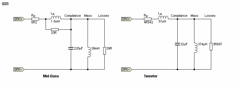
Figure 1 - Simulated Woofer And Tweeter
Figure 2 shows the impedance for the woofer and tweeter without any compensation. While your drivers will be different, the trend is the same. A woofer has maximum impedance at resonance, and the impedance rises beyond 250Hz due to the voicecoil's semi-inductance. Some drivers will show a more exaggerated rise, and some less. The use of a copper cap on the centre polepiece usually reduces the effect. Tweeters also show a rise above resonance, but it's usually fairly minor within the audio band. The biggest problem is resonance, which can seriously disturb the performance of the crossover. Ideally, the tweeter will be crossed over at no less than 2.5 times the resonant frequency, but in some cases it may be less - especially for tweeters with a higher than normal resonance.
All speakers have the same basic components that provide an equivalent circuit as shown in Figure 1. Voicecoil resistance is measured at 25°C, but it increases with temperature. The semi-inductance is difficult to measure directly, but it can be determined using a frequency-sweep, which will show the impedance rising beyond the minimum value measured (which is usually close to the voicecoil resistance (Re). You can calculate the approximate inductance, or use a speaker test box (such as that shown in Project 82 - Loudspeaker Test Box. This is a great deal easier than calculation, and gives a near-perfect result.
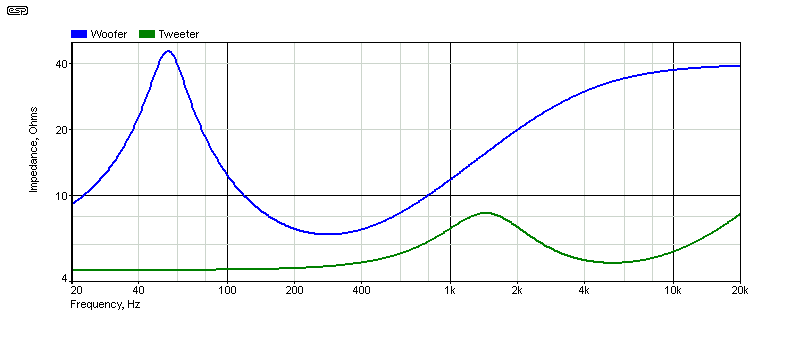
Figure 2 - Impedance Curves Of Simulated Woofer And Tweeter
The tweeter has a much flatter impedance curve than many others in the above graph, but the mid-bass is fairly representative of typical 125mm (5") mid-bass drivers. This will affect the crossover's response, but its effect is not pronounced. If you decide to use impedance compensation, there's a 'balancing act', because to get the impedance response flat may reduce the overall system impedance, and produces higher losses in the compensation networks. Impedance compensation is outside the scope of this article, which is about first-order series crossovers. This is the only network that will provide good results with no attempt at ensuring a flat impedance curve.
If you want to know more about impedance equalisation, see the article Impedance Compensation For Passive Crossovers.
While there are many very good reasons not to use first-order crossovers, with low-power systems (< 30W/ channel) they can be pretty much ideal. Unlike higher order networks, they can reproduce a perfect squarewave, which some people think is important. Whether you think this is worthwhile or not depends on your preferences, but it's fair to say that it usually makes no difference, because the modified wave-shape from high-order networks simply indicates phase shift. No-one has ever demonstrated that phase shift in any system is audible in a double-blind test.
Still, there is always something to be said for any system that can reproduce a squarewave, even if it's only for 'bragging-rights'. There are two ways that a 6dB/ octave crossover can be connected - series or parallel. Most people use parallel, because "that's the way it's always been done", but this loses one of the most valuable attributes of a simple crossover. Most of the simulations and examples you'll see elsewhere assume a resistance for the speaker, but to get a proper understanding of performance, you must use a simulated (or real) speaker. Failure to do so gives highly unrealistic results, particularly with parallel crossover networks.
Even with relatively low powered systems, there will be some voicecoil heating. The woofer (or mid-woofer) is affected more, because more of the supplied energy from the amplifier is below 3kHz. This can have a surprisingly large influence over the performance of the crossover network. A series network is self-correcting, and even using mismatched inductors and capacitors, it still provides a flat summed (electrical) response. There is no requirement for impedance correction, although performance may be improved by adding a notch filter tuned to the tweeter's resonant frequency. The very nature of a first-order series network is generally an improvement over the more common (and/ or 'conventional') parallel network.
The formulae for the crossover components are ...
CX = 1 / ( 2π × f × Z )
LX = Z / ( 2π × f )
CX is the crossover capacitance, LX is the inductance, Z is the speaker impedance (nominal or compensated) and f is frequency. For the drivers described here, I used a (pretty much random) value of 6.5 ohms for both drivers, and a crossover frequency of 2.5kHz. The capacitance (CX) works out to be 9.79µF (10µF was used) and the inductance (LX) is 413.8µH (424µH was used due to a typo when I ran the simulations). The difference is minor, so I didn't re-run the simulations and change the graphs.
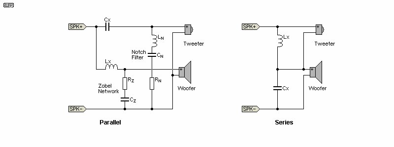
Figure 3 - Parallel And Series 6dB/ Octave Crossovers
If a series and parallel crossover are compared using a suitable resistor in place of the speaker, they are almost identical. However, loudspeaker drivers are not resistive, other than at a couple of frequencies - at resonance and at the 'minimum impedance' point which depends on the driver. For the majority of the frequency band, drivers are reactive, showing either inductance or capacitance. Resonance occurs at the frequency where inductive and capacitive resonance are equal, and only a resistive component remains. At higher frequencies, the impedance is heavily influenced by the semi-inductance of the voicecoil. It's never truly inductive, because there are losses (largely due to eddy-currents in the pole pieces).
The essentials are shown above - a parallel network requires impedance compensation. Without it, the final frequency response is a lottery, and it certainly won't behave as expected. The impedance correction involves a notch filter for the tweeter, and a Zobel network for the woofer. Without these, the response will be highly unpredictable (and rarely good). Other effects will also have an influence as detailed below. A parallel network has a lower overall impedance, mainly due to the compensation circuits (a compensated parallel version using the same drivers has an average impedance of about 4.5Ω between 400Hz and 10kHz).
With a series (6dB/ octave) crossover, the response will sum flat (electrically) regardless of speaker impedance variations (due to frequency, thermal effects, ageing, etc.) and the entire crossover network has been reduced to a single inductor and capacitor. The response (with the simulated drivers) is shown below, and it's as close to perfect as you'd ever want. All of the caveats of 6dB/ octave crossovers apply of course, so don't even think of using it in a high powered system. The tweeter will be stressed well beyond its design limits, and may suffer from serious intermodulation distortion. Continuous high power will cause the tweeter to die. In common with all first-order networks, serious anomalies in the woofer's high frequency response will not be attenuated very well. This means that cone break-up and similar (usually unpleasant) high frequency irregularities can affect the sound, so choose a driver that's well-behaved above the crossover frequency.
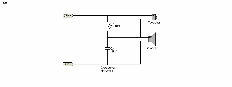
Figure 4 - Series Crossover, No Impedance Correction
While a series network is theoretically equivalent to a parallel network, this only applies when impedance correction circuitry has been added. The series network shown is as simple as it's possible to make a crossover. The inductor bypasses low frequencies from the tweeter, and the capacitor bypasses high frequencies from the woofer. You can include impedance compensation circuits if you prefer, but they are not required for flat response. With the simulated drivers, the crossover frequency was raised to 3.8kHz, largely because the tweeter has a lower impedance than the 'design' value.
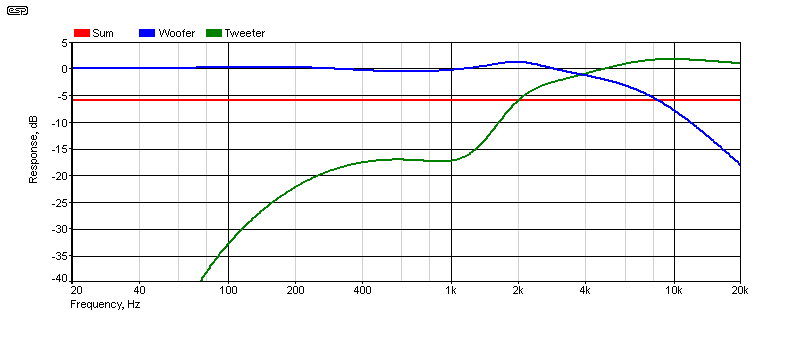
Figure 5 - Series Electrical Frequency Response
Although the individual responses of the woofer and tweeter show a peak before rolloff, the summed response is due to a combination of both amplitude and phase. If the summed response is flat, then the acoustic response will also be flat. There will always be discrepancies that cannot be accounted for in the electrical domain, but I've run acoustic tests that show that the response is as flat as the drivers will allow.
It's obvious from the graph that while the summed response is dead flat, everything isn't quite as wonderful as it seems. The tweeter's rolloff isn't sharp enough, and this will create issues if the tweeter can't handle the extra power. This means that some tweeters will exhibit higher distortion than expected. This is one of the reasons that I would only ever suggest a first-order crossover for low powered systems. Should the woofer suffer from cone break-up at higher frequencies, this too may be audible, because the crossover network can't reduce the energy quickly due to the low slope of the network. All crossover networks are a compromise, and first-order systems are no exception. Indeed, there are more compromises than with higher-order types, but they are more tolerant of parameter changes.
It's common for the tweeter to be more sensitive than the mid-bass, and it often needs some attenuation. With a series network, you don't need to be particularly fussy about maintaining the correct impedance, and the necessary level reduction can just be a series resistor, selected to attenuate the tweeter. For example, if the tweeter is 3dB more efficient than the mid-bass, just placing a 1.8Ω resistor in series with the tweeter will provide the 3dB attenuation required (assuming one with the same specifications as that used in this article).
Rather than repeating everything here, refer to the article Loudspeaker L-Pad Calculations, which covers the topic in detail. It includes a simple calculator that you can use to maintain the desired impedance while providing the attenuation needed. Mostly, you don't need to go overboard, especially with a series network. However, for the L-pad to work properly, it's helpful if an impedance compensation network (a notch filter) is used to keep the impedance constant.
The impedance compensation isn't required for a series first order network of course, and the small variations you'll get without it are likely to be less than the response fluctuations of the tweeter itself. Just adding the L-pad goes some way towards taming the resonant peak anyway, because it involves a resistor in parallel with the tweeter if done properly. Another alternative that's been used in some speaker systems is to have switched levels for the tweeter, usually (nominally) flat, +3dB and -3dB settings. I leave this to the reader.
We get used to seeing impedance plots that in some cases dip to very low values at certain frequencies, but the series 6dB/ octave network is fairly benign. A plot with no impedance equalisation is shown below, and it is mostly above 10 ohms, only falling to 3.8 ohms at about 6.5kHz. This is to be expected, since the tweeter has a voicecoil resistance of 4.5 ohms. A tweeter with a higher impedance will reduce the impedance dip.
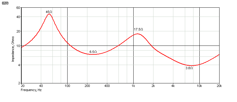
Figure 6 - Series Impedance (No Impedance Correction)
If the two drivers remained at exactly 8 ohms at all frequencies, the impedance curve is almost dead flat. There will be a small dip at the crossover frequency, but for two 8Ω (nominal) drivers it falls to 6.3Ω at 2.4kHz, with a very gentle slope (the 'notch' is 8kHz wide!). The impedance curve was produced using the same values as all other examples, and the only significant points are the resonant frequency of the two mid-bass, and the impedance peak roughly half-way between the tweeter's resonance and the crossover frequency. The impedance was measured using the same equivalent circuit for each driver as shown throughout this article. With an impedance such as that shown, no known amplifier will be at all stressed.
There's a great deal of complete nonsense on the Net about the 'audibility' of certain components, and capacitors seem to be the most commonly discussed parts. However, a frequency response test (under load) will quickly show that there is almost no difference between any two capacitors with the same ratings (in particular, capacitance and voltage). You can set up a null tester quite easily to prove to yourself that this is the case. While it's well outside the scope of this article to describe such a tester, you don't really need one. Choose good quality (but not necessarily 'audiophile') parts, with a generous voltage margin, and preferably with a low ESR (equivalent series resistance). This usually doesn't change by very much with most capacitors.
Polypropylene is generally the preferred dielectric, as it has low losses. This is important when a capacitor has to carry several amps of current at higher audio frequencies. In some cases, it may be cheaper to get 'motor start/ run' caps, especially when high capacitance is needed. While it might seem unlikely, polyester (aka Mylar® or PET) caps are also fine, provided they are rated to carry the current demanded by the drivers.
Bipolar electrolytics should be your last choice, and only if you can't get anything else. They have a finite life, much higher ESR than most film caps, and usually have limited current ratings. Be careful when you see claims that a capacitor's dissipation factor is a major factor in 'the sound'. Very few film capacitors have a dissipation factor that will cause any problems at audio frequencies, with the possible exception of bipolar electrolytic types. Even with these, it usually only becomes a problem as the capacitor ages, and that is a good reason to avoid them if possible.
Inductors are another matter entirely. As the world's worst passive component, you need to choose carefully to ensure that the DC resistance is low, and be aware of possible self-resonance. Even if it's outside the audio range, it is possible (albeit unusual) for self-resonance to cause power amplifiers some grief. There's a wide range available, with many from specialist ('audiophile') suppliers. Some of these may be very good, others can just as easily be awful - 'customer reviews' are meaningless and should be ignored (this also applies to capacitor reviews of course - many are unmitigated drivel).
The biggest issue with inductors is their DC resistance (DCR). This is present for both AC and DC, and it does two things (neither of which is desirable). When used in series with a woofer, the damping factor provided by your power amplifier is in series with the DCR (as well as the voicecoil resistance), and this reduces damping. Thin wire might make for a smaller inductor, but it will dissipate more power than a larger coil wound with thicker wire. It's a balancing act, and finding the optimum compromise isn't easy. Because of the resistance, the coil also dissipates power (as heat), and every watt 'stolen' by the inductor is a watt that doesn't get to the loudspeaker driver.
For example, if an inductor has a resistance of only 0.66Ω and handles a current of 5A (RMS, average, providing 100W into 4Ω), it will dissipate 16.5 watts. For a comparatively small component with little or no airflow, it can get surprisingly hot, and that increases its resistance even further (copper has a positive temperature coefficient of resistance) of 0.395% per °C, At a temperature of 150°C the same coil will show a resistance increase to 1Ω. It will now dissipate 25 watts! Quite clearly, low resistance is essential.
Some crossover coils uses a magnetic core, which reduces the size and DCR, but at the expense of linearity. Unless the core is much larger than theoretically required, it will suffer from partial saturation, and that introduces distortion. Saturation depends on current and frequency, and is worst with high currents at low frequencies. For a 'utility' speaker system that will only be used at low power, you'll probably get away with a magnetic cored inductor, but an air-cored coil is always better. However, it will almost certainly have higher DCR unless you go for something very expensive.
Resistors are generally benign, even 'standard' wirewound types. Yes, they have some inductance, but it's unlikely to cause any problems at audio frequencies. The response aberrations of almost all drivers will exceed any error cause by resistor inductance. The vast majority of resistors used in crossover networks are relatively low values, so exhibit only small amounts of parasitic inductance. Non-inductive wirewound resistors are available, but some are 'ordinary' wirewound types that have been marked (or sold) as 'non-inductive'. This is something I've tested and verified, and it's not a myth. In general, the inductance of most 'ordinary' wirewound resistors will be a few micro-Henrys, and rarely cause any problems.
The topic of component selection is covered in more detail in the Design of Passive Crossovers article.
I think that the conclusions pretty much speak for themselves. In the limited places where it's appropriate to use a first-order passive network, the series configuration wins every time. There's almost nothing you can do that will disturb the summed response, and testing with speaker measurement hardware will confirm that the acoustic response follows the electrical response as closely as the drivers will allow. You are more likely to see disturbances created by driver peaks and dips or diffraction than any variation of the response across the crossover region.
I haven't included any details of time-alignment, but first-order crossovers are sensitive to acoustic centre misalignment. Unfortunately, if you use a stepped baffle to align the acoustic centres, you'll create diffraction effects that can easily make the overall response worse. Some people use a sloping baffle to time align the drivers, but that means that the off-axis response has to be very good. This is not always the case, but the cabinet details are not covered here. When small drivers are used, the time difference will not normally be excessive, and the small 'wobbles' in response will usually be inaudible. For example, the small speakers used in my Project 73 system would have an offset of no more than 10mm (a time delay of 29µs). Sound travels at (about) 2.92mm/ µs if you want to work it out yourself.
In all of the cases shown (including elevated temperature), a squarewave is reproduced as electrically perfect, and any deviation is due to the drivers. No loudspeaker driver is free from peaks and dips, and adjacent drivers can cause diffraction, as will the edges of the enclosure. These can be hard to eliminate, and drivers should always be mounted so they are at different distances from the two sides, top and bottom. For information on cabinet bracing, vibration analysis and other aspects of cabinet design, see Loudspeaker Enclosure Design Guidelines.
One thing that you must be aware of is that all passive crossover networks rely on (close to) a zero ohm source impedance. Most transistor amps provide this, and while it's never really 0Ω, it's close enough. Very few valve (vacuum tube) amplifiers have a low output impedance, especially 'low-feedback' and 'no-feedback' designs. All passive crossovers are affected, and obtaining flat response is extremely difficult. The crossover can be designed to work properly by including accurate impedance compensation. If the impedance appears purely resistive, the crossover can be designed to function (more-or-less) normally regardless of small source impedance variations. This is very hard to achieve - the compensation networks need to be very accurate, with the smallest possible impedance variation with frequency. High output impedance also limits electrical damping of the driver at its resonant frequency, so bass response is usually exaggerated.
Next time you put a small speaker system together, try the series 6dB/ octave network. It's highly unlikely that you'll be disappointed. It's not perfect, but it will give good results where a first-order system is appropriate for the drivers you are using. An active system (using an electronic crossover) will win hands down every time, but isn't always feasible. For example, I use a speaker using drivers very similar to those described here to test amplifiers (and often to listen to music in my workshop). An active system would mean that I couldn't use a single amp, and that's very limiting when one needs to make comparisons between amplifiers!
 Main Index
 Articles Index