
|
| Elliott Sound Products | Project 82 |
Testing loudspeakers is covered in some detail in the passive crossover article (see Design of Passive Crossovers), but it is irksome at best to have to fiddle about with clip leads and components lying all over the workbench. This simple project is intended to make life that little bit easier when you are trying to determine the optimum frequency compensation network for woofers and midrange drivers.

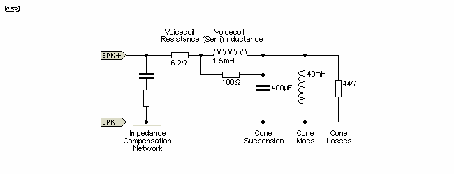
Figure 1 - Loudspeaker Equivalent Circuit
The above is a 'typical' equivalent circuit of a loudspeaker. Resonance is not an issue, as it's well below the expected crossover frequency for a tweeter. Because of the voicecoil's semi-inductance, the impedance rises above 400Hz, and the impedance can be seen to be changing rapidly above 1kHz. If you don't apply impedance compensation, the impedance change around the tweeter's crossover frequency varies so much that the performance will be seriously degraded. See the Design of Passive Crossovers article for complete details. The compensation network is placed as shown - directly in parallel with the speaker driver, and after the crossover network. The power rating for the compensation resistor may be quite high, depending on the amp power. If used with a reasonably powerful amplifier (50-100W), expect to use at least 20W, although it could easily require more with a big power amp.

Figure 2 - Impedance, Before (Green) & After (Red) Impedance Compensation
The green curve shows the impedance, and it's quite obvious that a passive crossover can't be expected to provide a smooth response with the impedance changing so drastically over an octave or so below and above the crossover frequency. When a suitable R-C combination is found using the test box described here, the red curve shows that the impedance is commendably flat (within ±0.5Ω) from 550Hz to 12kHz. A (passive) crossover network can now provide a well defined crossover frequency with minimal phase shift across a wide frequency range. If this is not done (and many systems make no attempt at impedance correction) the end result is a lottery (and with similar odds against getting a good overall response). Needless to say, none of this is necessary if you use an active crossover, but sometimes it's not practical.
If you are interested, the impedance compensation shown was achieved with a capacitance of 22µF and a series resistance of 8.2Ω, which is easily (and quickly) found using the test box.
They don't come much simpler than this. A suitable plastic box, a couple of switches, 4 combination binding posts / banana sockets, a handful of capacitors and a wirewound pot complete the entire project.
Of all the components, the pot is most likely to cause problems. The suggested value of 30Ω was used in my case because I just happened to have one lying around in my junk box, but they aren't always easy to get. A very basic tweeter attenuator (a simple pot) will work OK, and the value is not that important. Even a resistance as low as 8 Ohms could be used, with a switchable 8.2 Ohm resistor in series so that the range will be from 0 to 16Ω (near enough). I shall leave it to the individual to determine the best way to achieve the required range, which is typically 0 to 20Ω. Up to 50Ω is ok, but if the total resistance is any higher, low resistance values will be difficult to set accurately. The resistance needed is usually just a little over the DC resistance of the loudspeaker driver. While slightly better results can be obtained if the resistance is the same as the VC resistance, this causes higher dissipation and isn't necessary.

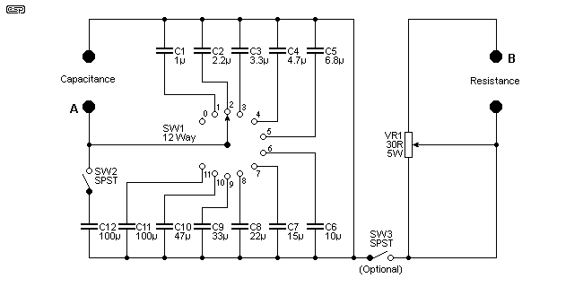
Figure 3 - Complete Circuit of Test Box
The switch SW2 and associated 100uF cap is optional, and increases the range up to 200uF - in most cases this won't be necessary though. The caps are all bipolar electrolytics, and this is perfectly OK, since they will never be used at high power, and their sound quality is not important. SW3 (optional) allows you to connect the resistance and capacitance in series without needing a jumper lead. The terminals marked 'A' and 'B' are used if the switch is on.
To use the box, simply connect it across the speaker - mostly you will want the caps and pot in series, so a lead between the two (or even a switch) makes this easy. From the output of suitable small amplifier, place a 100 ohm or so resistance in series with the output, which should about 1-2 Volts at most. Sweep the signal frequency across the speaker. Resonance will not be affected, but there will be a 'magic' combination of capacitance and resistance that will make the impedance above resonance completely flat. No maths, no spreadsheets, just a quick frequency scan and twiddle a couple of knobs to get the values needed to ensure that the crossover actually will work at the design frequency.
The network derived from the testing will be placed in parallel with the speaker, and prevents the rise of impedance with increasing frequency. This rise is caused by the semi-inductance of the voice coil, and if not accounted for it plays havoc with the performance of any passive crossover network.
One of the most difficult measurements to make in audio is impedance, but this is also made relatively simple. Keep the 100 ohm resistor in series with the amp's output, and carefully measure the voltage across the speaker at the crossover frequency - this will be much the same as the voltage anywhere else outside of the resonance affected area of the impedance plot when an impedance corrected Zobel network is in place.
Disconnect the speaker, and without changing anything else, connect the pot instead. Adjust the pot until the voltage is exactly the same as you measured before, when the speaker and parallel network were in place. Disconnect the amp, and measure the resistance of the pot - this is the speaker impedance, and this is the real impedance - not the 'nominal' impedance. It is the actual measured impedance that must be used to calculate the crossover network components.
Don't change the frequency from the generator or the amp level just yet ...
In many (OK, all) cases, it is highly recommended that the tweeter is also measured for impedance, and a resistance used in parallel so that the impedance at crossover exactly matches that of the woofer or midrange driver. Simply connect the tweeter across the amp, with the pot in parallel. Carefully adjust the pot until the voltage is exactly the same as that measured before (this is where a pot that goes up to about 30 Ohms is useful). When the voltage is the same, disconnect the amp and tweeter, and measure the setting of the pot. This is the resistance that should be used in parallel with the tweeter to make everything work properly.
This is a simple procedure that works extremely well, and my test box has been used quite a few times since I built it. The measurements described in the Design of Passive Crossovers article work well, but this is much quicker, and is 'real', in that you can see the effect of varying resistance or capacitance easily. There will nearly always be a compromise in the crossover design, and this little test box lets you see exactly what happens, and select the best possible combination for the speaker drivers you are using.
A reader suggested a variation that gives more capacitance values by adding a second switch so that existing and additional caps can be connected in parallel.

Figure 4 - Complete Circuit of 'Alternate' Test Box
Garth wrote ...
I was very taken with your loudspeaker test box. The only problem I can see is that E6 capacitor values have big gaps between them. It struck me that another rotary switch would allow selection of two of the capacitors in parallel. With another two extra caps you can cover the same range (well, to 197µF instead of 200) in smaller steps.
Extra cost is only the caps; SW2 becomes a 12 way rotary instead of an SPST toggle. Don't know about Oz, but in the UK at the moment this actually reduces the cost slightly! I can see myself building two, it should be such a useful capacitance box for quick crossover tests etc.
I thought it was useful enough to include, so if you think that the extra flexibility would be worthwhile, then this is a good way to get many different values for minimal extra cost. I leave it to the reader to work out how to label the switches. Note that some switch combinations aren't useful because the two switches can select the same capacitor. For example, SW1.5 and SW2.2 both select C5, and the capacitance will only be 4.7µF.
Given that the cost of mini-toggle switches can be quite low, this final arrangement is far easier to wire up, and provides the greatest possible flexibility. You can likely remove the capacitors above 47µF if you wish, because it would be a rather strange driver that needed more (and you can still get up to 146µF with all the switches turned on). The only time you might need large capacitor values is for low resonance, high excursion woofers, as they may have a much higher voicecoil semi-inductance than smaller drivers.

Figure 5 - Complete Circuit of Simplified Test Box
The pot's power rating can be reduced too, because the measurement will typically be made using very low power (there is absolutely no need to use more than a few milliwatts). In many cases, the speaker can simply be driven using the output of a signal generator, because you only need enough level to be able to measure the voltage across the loudspeaker. Even if you use a power amplifier, you'll typically take measurements with a 100 ohm resistor and a voltage of no more than 1V RMS across the speaker within the 'flat' portion of the impedance curve (typically around 200Hz - see Figure 2).
 Main Index
 Projects Index