

|
| Elliott Sound Products | Project 73 |
 All required PCBs are available for this project. Click the image for the price list.
 Main Index Main Index
 Projects Index Projects Index
|
If you like listening to music while using your PC, or enjoy games with all their sound effects, you will generally be disappointed with most of the PC speaker systems available. Few systems use anything other than moulded plastic boxes, ratty little tweeters that don't really do very much at all, and commonly using only a tiny bipolar electro as the 'crossover'. Zero acoustic damping and perhaps as much as a 5W amplifier (if you're lucky) completes the picture. Many don't even bother to fit a tweeter.
As for the sub-woofer, if it manages to wheeze its way down to 50Hz you are indeed fortunate, and with as much as 20W in a tiny ported plastic enclosure you can think yourself lucky to get that far. I know this from experience, and eventually got so sick of the grossly inferior sound that I just had to do something about it.
This is not so much a project in its own right as a collection of existing projects, and using boards that are available (see the price list for details). With a bit of work and not too much of a hit to your finances, you can make a PC speaker system that will outperform most small hi-fi systems.
There are two parts to the project, small satellite speakers that sit on the desk next to the monitor, and a sealed, equalised sub-woofer that also contains all the amplifiers, power supplies and other electronics. The sub extends happily to 30Hz, depending on where it's installed. It makes quite a good account of itself considering its size. Ideally, the sub will be mounted at (or close to) the boundary of a wall and the floor so there is some reinforcement provided by the 'quarter-space' loading. It also makes a fine foot rest if it's under your desk. 
Is this an audiophile project - no. However, it is head and shoulders above any PC speaker system I have ever heard, regardless of price, and is also a great little system for any additional rooms where music is desired. The sound is very clean, and it has extended lows that put a lot of 'proper' systems to shame.
The selection of speaker drivers is up to you, since I have no idea what you will be able to get from your local suppliers. Don't be too cheap - the better the drivers, the better the overall sound, and the happier you will be with the end result. At the other end of the scale, using the best drivers you can find is probably not worth the effort either, since there is already a limitation in sound quality imposed by your sound card.
Please note that all dimensions shown are in millimetres. For those who insist on those inch thingies, divide by 25.4. Litres can be converted to cubic feet by dividing by 28.
The parameters of the speaker drivers I used are shown below. These cost me a little under AU$150 from local Australian suppliers. The only speaker likely to be recognised is the Peerless tweeter. Both the woofer and midrange drivers have rubber roll surrounds, and the boxes are packed with fibreglass 'wool' or other suitable damping material.
| Woofer | Re/sponse 200mm | Midrange | Unknown 100mm | Tweeter | Peerless 812978 |
| Impedance | 8 Ohms | Impedance | 8 Ohms | Impedance | 8 Ohms |
| Power | 120 W | Power | 30 W | Power | 100 W (Note 1) |
| Sensitivity | 90 dB/W/m | Sensitivity | 91 dB/W/m | Sensitivity | 91 dB/W/m |
| Resonance | 40 Hz | Resonance | 91 Hz | Resonance | 907 Hz |
| Total Q (Qts) | 0.47 | Total Q (Qts) | 0.72 | Total Q (Qts) | 0.8944 |
| Vas (litres) | 32.8 | Vas (litres) | 2.11 | Vas (litres) | n/a (Note 2) |
| Cone Area (m²) | 0.0214 | Cone Area (m²) | 0.005 | Cone Area (m²) | n/a (Note 2) |
1 This is the nominal system power - the tweeter would self destruct with this power within its normal operating range
2 n/a - Not Available / Not Applicable
The above information is mainly for the sake of interest. The drivers you use will have to be those you can obtain, but the above figures give you a goal to aim for. If you can get drivers with similar specs, then you will have a system as good (or better) than mine.
Firstly, if you are still using a CRT (cathode ray tube) monitor, you need to obtain some magnetically screened drivers. Ordinary drivers must not be used, as they will distort the colour and even the picture shape on your monitor. If you have an LCD monitor, magnetic screening is not necessary. The midrange drivers I used are 100mm diameter (outside) and are rated at 30W RMS or 50W peak. The midrange and tweeters are both 91dB/W/m and are 8 ohms. The crossover is a simple series passive 6dB network at 4kHz. This is not ideal, but is a reasonable compromise between complexity and performance. With an internal volume of about 3 litres, the boxes are sealed, well damped with fibreglass, and have a resonance of 110Hz.
It is important that the low-midrange driver and tweeter have the same efficiency. If not, make sure that the tweeter has the higher efficiency so it can be padded back to match the midrange. If not, you will have to pad the midrange driver, and this will soak up much more power (as heat), and reduces damping - neither is acceptable. A simple resistive pad can be used to reduce the tweeter level, or you can use a 'proper' wirewound attenuator pot so it can be adjusted.
The boxes are covered with 'carpet' (the thin felt-like material sold for covering speaker boxes), which helps to reduce diffraction, and adds extra damping to the box panels. The boxes themselves are made with 10mm medium density fibreboard (MDF) and because of their small size they are extremely rigid, even with no additional bracing.
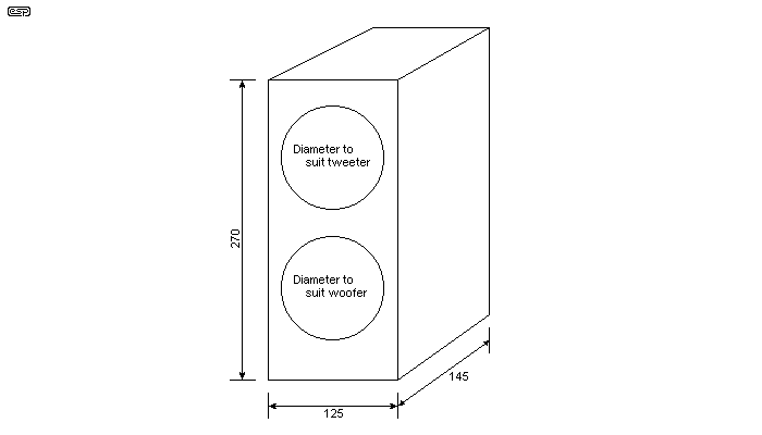
The boxes measure 125(w) x 270(h) x 145(d) outside. I rounded off all the edges with a router, but this is not really essential if you don't have access to one. If you do, use a rounding bit with no more than a 10mm radius, or you will remove too much of the material next to the joins. Use of corner braces is recommended, but if the glue is properly applied they may not be needed. Use of corner braces allows the use of a larger radius for rounding the edges if desired.
The crossover consists of a single 470µH inductor and a 3.3µF polypropylene (or polyester) capacitor, wired as shown in Figure 2. This is a 6dB network, so it is important to make the crossover frequency high enough to ensure that there is sufficient attenuation at the tweeter's resonant frequency. I measured the woofer's impedance at 4kHz, and found that it was only marginally higher than at the midband frequency (about 400Hz), so decided against using an impedance correction network. Although I'm sure that this would improve matters, I suspect that it would be marginal, and not really worth the effort.
You may prefer a lower crossover frequency, as the suggested values will cross over at about 8kHz. I wouldn't increase the capacitance to any more than 10µF though, as that may put the tweeter at risk (the crossover frequency is then 3.5kHz). A 6.8µF cap will set the crossover frequency to about 4.7kHz which should still protect the tweeter and it relieves the little midrange of some of it's high frequency duties. Because it's a series network, the inductor doesn't need to be changed.
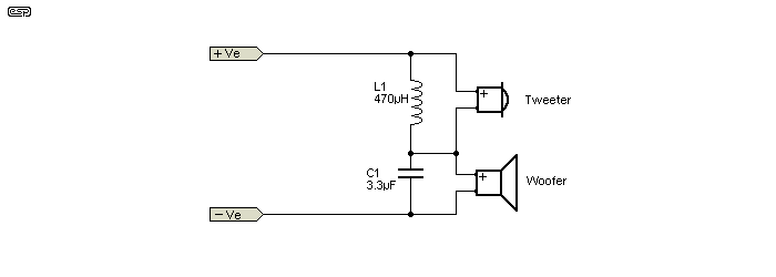
I established some time ago that the series connection for a 1st order filter is to be preferred, and that's what is shown. Using the values given with a parallel crossover network will almost certainly leave you with a substantial frequency dip between 3-4kHz. A series crossover is no more difficult to make than a parallel version, and it not only works much better, but is 'self correcting' to a degree. (See Series Vs. Parallel Crossovers for more details.)
The connectors that I used were some I happened to have in my junk box, and are actually the 2-pin microphone connectors that are commonly used on CB radios and the like. They are small, airtight, and cheap (even if you have to buy them), but are a pain to mount, as they are intended for mounting in sheet metal. I recessed the mounting hole using a SpeedBor flat wood drill, and secured the final assembly with hot-melt glue. Feel free to use any connector and mounting that suits you.
This is where all the action is, and I used the following project boards to make the final unit ...
The 'subwoofer' to main speaker electronic crossover is (as always) a compromise. The frequency has to be low enough to ensure that the sub can't be localised by ear, yet high enough to ensure the main speakers aren't overloaded. I chose 112Hz because it fits the criteria and uses nice common values for the filter networks - 10k and 100nF. See the Project 09 article for all the details.
The entire system is powered from a 25-0-25 160VA toroidal transformer. I suggest that you don't use less than this or power will be restricted. With the 160VA transformer, power is less than the maximum the system can do, but is more than enough for the drivers used. Total system power is around 200W, but can exceed this on transients. This is very loud (as in VERY loud), and may be considered overkill. Feel free to use a lower supply voltage, but the system as described can also be used as a small hi-fi and will give a good account of itself in this role.
Reducing the power will limit your options, but since the system is generally used as 'near field' (listening position within 1 metre of the main speakers) you don't need as much as you might think. At ~90dB/1W sensitivity, a mere 10W will give you a peak level of over 103dB SPL at one metre - this is more than enough, and I have been using the system as described for over 10 years, and have never found it underpowered (quite the reverse in fact). Mine is rarely run at more than 1-2W average power.
The sub-woofer cabinet needs to be big enough to house the speaker, amplifiers, and the other electronics. For the sub driver, I used a 120W 200mm poly-cone, because it was reasonably close to what I knew would be needed for the job. Selection criteria for the sub are basically ...
The above may sound like a tall order, but such drivers exist at reasonable prices - I know, because I bought one. As with the satellite speakers, there is no point getting the best driver you can - it needs to be able to do the job without distorting (too much). Remember that this is a PC speaker system, and makes no pretensions at being audiophile hi-fi. In common with most compact systems, extended bass (below 30Hz) isn't available because the driver is too small. I doubt that anyone would need a 300mm driver for the extra bottom end, but you can use one if you wish.
My sub box has an internal volume of about 22 litres - not accounting for speaker displacement and the volume taken up by the electronics. This is quite small, but more than acceptable for all normal listening. I used 16mm MDF, which is again very sturdy and shows little or no signs of resonating because of the size. The box measures 480(w) x 280(h) x 230(d), and again I rounded the edges - not because of diffraction, but I knew I would use the sub box as a footrest, so I wanted comfortable. 
The box is made with a removable back, secured with lots of screws and sealed with foam tape to prevent air leaks. The back carries all the electronics, with the exception of the power transformer - the latter is mounted on the base of the sub box - as far from the electronics as I could get it. This is important (if somewhat inconvenient), because the system has high low-frequency gain, and hum and buzz from the transformer is all too easily picked up.
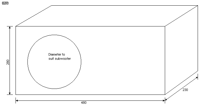
The enclosure is not critical, but you will need to do something before you start hacking holes in the back (removable!) panel. Bolt the speaker in position. You need to do this anyway to make sure that everything fits, but in addition, include the fibreglass or other acoustic damping material, and solder a couple of thin wires to the speaker. Bring them out through a screw hole and screw the back into the box using half the screw holes. Now you can measure the speaker's resonant frequency in the box.
Attach an audio oscillator to the speaker leads. If your oscillator has a low output impedance (such as a sound card sinewave generator), then you will need a resistor in series - about 560 ohms will do fine. Carefully adjust the frequency around the expected resonance frequency (in the vicinity of 50Hz if you chose your woofer wisely). The frequency where the voltage across the speaker terminals is highest is the resonant frequency, and you will need this to double check the figures from the Linkwitz transform spreadsheet. This represents the unequalised -3dB frequency.
Using the spreadsheet, insert your speaker parameters in the 'Box' page, and include the internal volume of your cabinet. The spreadsheet will calculate the values you need to properly equalise your box. In the main page of the spreadsheet, select 30Hz as the -3dB frequency, and select a Q of 0.8 for best results. The resistor and capacitor values obtained will be used in the Linkwitz transform circuit board. Have a look at the frequency response graph, and verify that the unequalised -3dB point is within a few hertz of the resonant frequency you measured. If it is not, you may need to 'fiddle the numbers a little until the graph and your loudspeaker measurement agree. Small errors are insignificant, as room acoustics will have a much greater effect than an error of a few hertz.
Finally, all the bits and pieces can be hooked up together. Figure 4 shows the final block diagram of the low level circuitry, and includes a level control so the bottom end can be matched to the satellite speakers. There is a deliberate 6dB extra gain in the low end to allow this, and it will normally be enough to compensate for different speaker driver efficiencies as well.
The low level electronics should be mounted on a piece (or pieces) of un-etched printed circuit board, or some aluminium sheet. The sheet must be connected to the input earth (ground) point, or it will be worse than useless. This provides some shielding, but make sure that whatever you use is securely attached to the rear panel so it can't rattle. If you wanted to, the low level stuff can all be mounted in a diecast aluminium box, but this is not really necessary unless your electrical environment is very noisy.
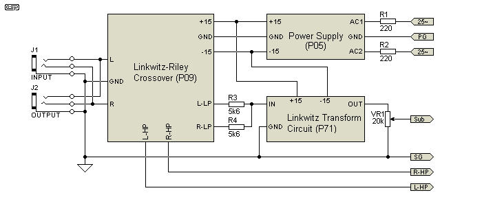
The input jacks are simply wired in parallel, so you can take an additional feed to other equipment. If you don't want to do this, leave out one of the jacks. The Linkwitz-Riley crossover is configured for a crossover frequency of 112Hz, which is nice and easy - all frequency setting resistors are 10k and caps are 100nF. None of the output buffers and trimpots (etc.) are used, so leave out these sections of the circuit. The two low pass outputs are simply summed with the 5k6 resistors (R3 and R4). These resistors can be mounted on the L-R board, with the signal taken from the topmost trimpot hole. You can easily work out the full wiring from the L-R crossover assembly instructions. If you prefer a different (and/or variable) crossover frequency, you can use the Project 148 state-variable crossover network instead of P09.
100 ohm resistors must be used in series with the high pass outputs, since shielded cable will be used to connect to the P19 power amp board. Without the resistors, the opamps can oscillate. These too can be easily mounted on the board.
The low pass combined output is connected to the input of the Linkwitz transform circuit, which will equalise the subwoofer to obtain a flat response down to around 30Hz. The output of the transform circuit is connected to a pot as shown, and this needs to be accessible from outside the box so the system can be set up properly.
All the low level circuitry is powered from a P05 preamp supply. Note that I included 220 ohm resistors in series with the AC input - these must be 5W wirewound types. Since 35V is the absolute maximum DC input voltage for the 7815 and 7915 (or 317/337) regulators, direct connection to the transformer would lead to a potential over-voltage, and the resistors tame that very nicely. The DC input to the regulators will be typically about +/-22V with this arrangement.
NOTE:- Do not operate the P05 supply without a load from a 25-0-25 volt transformer.
Figure 5 shows the power amplifier connections. The P3A (60-100W) amp is wired up using a 22k bridging resistor. An insulated wire link is needed between the output of the Right channel and a 22k bridging resistor to the feedback junction (base of Q2) on the Left channel. The input of the Left channel should be grounded with a wire link on the board. If preferred (and it definitely works better), you can use a P87B balanced line driver or a simple unity gain inverter to drive the Left channel, rather than using the resistor. This prevents a turn-on/off 'thump' that always occurs when the resistor bridging trick is used. The inverter can be wired using a TL071 and a small piece of Veroboard.
If you make the inverter, it only needs the opamp, two 10k or 22k resistors, and a pair of 100nF bypass caps for the opamp. The amount of Veroboard needed is tiny, and the whole circuit can be encapsulated in a short length of heatshrink tubing. You'll need 5 wires - +15V, -15V, Gnd, input and output.
Note the 10 Ohm resistor and 100nF cap in the ground lead of the P3A power amp. This provides the high frequency ground, but the main earth line is back to the preamp (actually the crossover and equaliser). Likewise, a 1 ohm (1W) resistor is in series with the power ground to the preamp supply. These resistors were used to ensure continuity, but not allow any ground loops which will cause massive hum.

| Please note that there's a mod needed to the P3A amp to bridge it. The left input should be shorted (still use the resistor and cap - just short the input terminals).
Both sides of the amp are built according to the construction article. Next, add a 22k resistor from the right speaker output to the junction of R4, R5 and Q2 base. This provides
bridging within the amp itself. It used to be included on the PCB, but was removed in later revisions of the board. Make sure that the extra resistor and any wiring is insulated with a
length of heatshrink or similar. However, while this works (very well) it does cause a large turn-off 'event'. It's better to use one channel of a P87b balanced line driver to split the signal, with each P3A input driven from the P87b. This will make the turn-off almost completely silent (see above text). |
The crossover inputs are the ground reference for the whole amplifier, and the ground is physically connected to this point, where the input connectors are in contact with the input panel. This is shown in Figure 4.
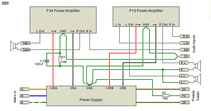
I know that the diagram is a bit of a jumble, but it actually does make sense.  All audio leads should be shielded at the amplifier end only. Do not connect the shields at both ends, or you may create an earth loop, and hum will surely result.
The P19 50W IC power amp board provides the left and right channel feeds for the satellite speakers. These require a connector for the satellite boxes, and although fixed leads can be used, I don't recommend it. All leads should be detachable, as dangling leads are a safety hazard when you are carrying the box - be warned, it is quite heavy when everything is installed. Note that you can use the P127 power amp board (2 x TDA7293 power amp ICs) instead of P19 if you prefer.
Heatsink selection is very important. Do not skimp on the heatsinks, as this is a fairly high power system, and needs as much heatsink as you can afford. Use a separate heatsink for each amp module, and each should be no smaller than 1°C/W. You may be able to get away with less if the system will never be driven hard and/or you reduce the supply voltage. Bigger heatsinks mean cooler running and longer life. The amplifier modules must be tested as described in the construction details before you apply power to the finished unit.
The earthing arrangement is very important, and may need some experimentation to get it right. As shown in these diagrams, it should be OK, but your layout will be different from mine, and this can have an influence on the final configuration. Note that the mains earth and signal earth must be joined, but only at one place. This is the classic 'star' earthing, and must be used to avoid hum loops and other buzzes and noises. I made the star earth point the common connection between all four filter caps, and this has proved quite satisfactory. This is also the speaker return point for the satellite speakers - the sub-woofer driver is connected to the amp in bridge, so it has no earth return.
All shielded wiring should have the shield earthed at one end only. Do not rely on the shield to complete the earth connection, as noise will almost certainly be injected into the signal lead.
 | WARNING Mains wiring should be carried out by qualified persons only. Do not attempt construction unless suitably qualified. Death or serious injury to yourself or others may result from a seemingly insignificant mistake. |
 |
Finally, Figure 6 shows the power supply in detail. As you can see, it is a dual supply, with only the transformer as a common point. This is not absolutely necessary, but does improve power output a little, and also prevents any possible interaction between the amps. I used an aluminium bracket fabricated from scrap sheet to secure the filter caps and act as a heatsink for the bridge rectifiers (I used 35A bridges - you don't have to, but they run cooler and are more reliable than smaller ones). The capacitors are mounted to the bracket using double-sided tape, hot-melt glue and a cable tie - I didn't want them to rattle, and you won't either.
I recently had a main filter cap fail (intermittent high ESR) which caused a very annoying hum, and the filter caps were replaced with 10,000uF types. Overkill, but it is very quiet and I have more reserve power for transients - I might even use the reserve one day.  Feel free to use as much capacitance as you like, but more than 10,000µF for each supply is unlikely to be of any tangible benefit.
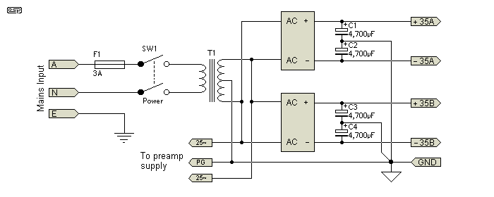
The power supply mains wiring must be performed by a suitably qualified person, and all connections must be shrouded with heatshrink tubing to prevent accidental contact. The use of a fused IEC mains connector is highly recommended for the mains input. The designators 'A', 'N' and 'E' mean Active (Hot), Neutral (Cold) and Earth (Ground) respectively. If you don't understand this - don't even try to wire it!
As previously discussed, I suggest a 25-0-25 volt transformer, preferably rated at 160VA. You will need to use an inline plug and socket or terminal block (mains rated!) for the incoming AC, since the IEC mains input connector, fuse and power switch will be on the back panel, and the transformer is mounted in the case. The secondary leads should be connected using heavy duty cables, and a terminal block to join the transformer output to the bridge rectifiers and a separate light duty feed to the preamp supply.
To give you a better idea of how everything fitted together in my system, Figure 7 shows the mechanical layout on the rear panel. Yours will probably be a variation on that shown, since the heatsinks must be accommodated, and yours will be different from mine. Make sure that signal and power leads are well separated, and keep speaker leads well clear of all signal leads, boards and inputs in particular - you don't need an RF oscillator!
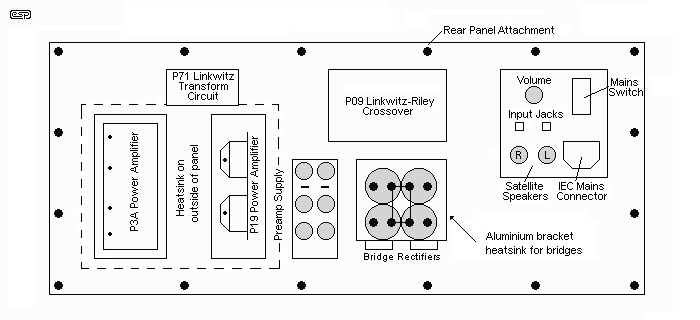
The heatsink for the power amplifiers is shown dotted. This mounts on the outside of the rear panel, and must be securely fastened and sealed. The amplifiers are mounted directly to the heatsink through the holes shown (you may only need one hole, depending on your heatsink). The sheet aluminium bracket is used as a convenient mounting point for the power supply filter caps, and is also the heatsink for the bridge rectifiers.
Once everything is tested and operational, you can complete the final assembly. Make sure that nothing on the rear panel rattles before you screw it into position, and ensure that the box is completely sealed. Even a small hole will make noises at low frequencies, because of the large cone excursions and internal pressure. When powered on, the system should be silent after the small initial transient from the amps. Careful listening will reveal a slight hiss from the tweeter - this is quite normal.
Connect the system to your PC and hear your music and games as you have never heard them before. Be prepared to make more than one unit, as your friends will be green with envy after they hear yours!
 Main Index Main Index
 Projects Index Projects Index
|