
|
| Elliott Sound Products | Project 62-E |
The circuits shown here comprise miscellaneous circuits not covered elsewhere, as well as various interconnections, DB-15 connectors and general cabling recommendations.
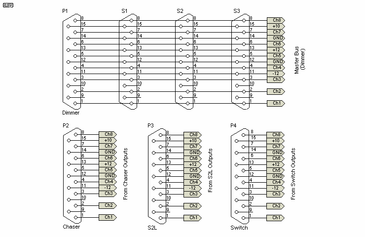
Each of the separate console controls (faders, switches, sound to light and chaser) has a plug reference, and the fader outputs are considered the master. While the other controls have their own output connector, they are easily connected to the master by means of jumper cables as shown in the preceeding section. The connectors are shown below ...

Figure 13 - Input and Output Connectors (DB15)
The power connections, namely +12, -12, +10 and GND should all be in parallel from each connector. While this would cause major problems with any audio system, in a lighting controller there will be no issues.
The audio input is shown in section 2 (sound to light), and will typically be a stereo jack socket. The strobe output can be anything you like, but a jack socket is suggested to retain cable compatibility.
Strobe, chaser and sound to light (S2L) are not imperative for a basic lighting console, and PCBs are not expected to be available for those modules. I am further contemplating (and only contemplating!) a PC controlled version. I have yet to decide whether to go for a simple parallel port interface or DMX512 - if you have any feedback on this, let me know. Bear in mind that DMX512 is a lot more difficult to implement, requires a dedicated microcontroller, and will be more expensive.
One possibility for further development is a MOSFET based trailing-edge dimmer. These are much kinder to electronic loads as used in all LED lamps, but are considerably more complex than TRIAC dimmers.
| Overview | Faders & S2L | Strobe & Chaser | Power Control | Connections | Miscellaneous |
|---|
 Main Index
 Projects Index