
|
| Elliott Sound Products | Project 62-B |
The strobe controller is essentially a stand-alone device, even though it is part of the console PCB. It connects through a two-wire cable to the remote strobe head. Control, input source selection and output routing are on the console.
WARNING - Strobes can be DANGEROUS and can induce epileptic fits. Use sparingly and with caution. |
The input to the strobe controller and/or chaser is either through a bass-beat extractor circuit or a free-running oscillator, both of which are shared by the chaser and the strobe controller.
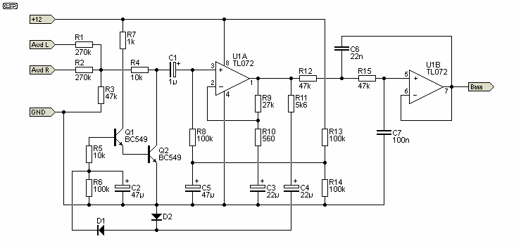
The bass beat extractor is shown in Figure 5, and consists of an automatic gain control circuit followed by a low pass filter. The output from this circuit is fed to the next, which converts the beat into a sharp pulse suitable for triggering the strobe or chaser.

Figure 5 - Bass Beat Extractor
This circuit uses only the +12V supply. The limiter circuit will not win any prizes for linearity or distortion, but this is of no consequence for this purpose. The diodes are 1N4148, resistors are 1/4W. Capacitors should be rated at 25V minimum.
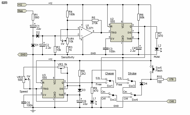
The controller is based on a pair of 555 timers. One is used to clean up the bass signal into a suitable pulse, and the other is running as an astable oscillator. The maximum frequency can be limited by adjusting the trimmer and the speed control through the front-panel control. The switches select either the bass-beat extractor output, or the free-run oscillator described here.

Figure 6 - Strobe and Chaser Controller
The first section is used to capture the bass peaks. The sensitivity of the bass beat extractor is adjusted with VR1. The free running oscillator is based on U3, a 555 timer, and the speed is controlled by VR2. VR3 (a trimpot) is used to set the maximum frequency. The switching determines if the strobe and/or chaser are controlled by the oscillator or the bass beat, and each is independently selectable. The signal to either can also be switched off entirely. The Flash button is used to create a single strobe flash - really useful for creating lightning effects. Diodes are 1N4148, resistors are 1/4W. Capacitors should be rated at 25V minimum.
The chaser was developed out of an urgent need by one of the directors of a show I was involved in. It was designed, de-bugged and constructed in a single evening - because the director wouldn't take no for an answer (show me a theatrical director who does!). Consequently, it is simple in the extreme - but still effective.
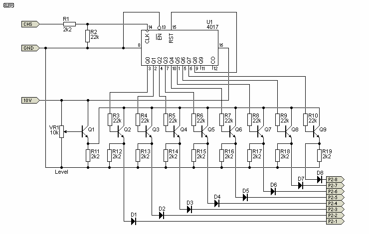
It is based on a CMOS 4017 decade counter, forced to reset at the nine count and resume from count 1. There are eight steps in each cycle before it repeats itself. Outputs are routed through the usual diode-coupled precedence hook-up. Input is either from the bass-beat extractor or from the free-run oscillator.
The chaser level control allows you to adjust the light level - if this is omitted, the lamps will flash at full brightness, which may not be desirable. With the level control shown, the maximum brightness will actually be a little lower than fully on - this is unlikely to be a limitation, as the light level difference will be barely noticeable.

Figure 7 - Chaser
The circuit uses transistors to buffer the outputs from the CMOS counter. This is done for three reasons. Firstly, the output current from a CMOS IC is not great, and the buffers provide protection from external static fields which will damage a CMOS device instantly. Last but by no means least, is that the level control would not be possible otherwise. All transistors are BC548 or similar (e.g. 2N2222), and diodes are 1N4148, resistors are 1/4W. Capacitors should be rated at 25V minimum.
| WARNING - The circuitry in a strobe head operates at very high AC and DC levels. These voltages are LETHAL. Take adequate precautions when testing, fault-finding and so on. If you are unsure of how to work with potentially lethal voltages - do not attempt to build this circuit. Ask a competent person for help. |
Brian said that he is not at all comfortable designing, testing and building circuits like this. To quote his words at the time ... "The voltages are very high, with some potentially lethal potentials lurking behind capacitor terminals. So, in my typically cowardly fashion, I went looking for a solution on the web, and found something. It works well, is relatively simple and the parts are easily acquired."
The strobe circuit was not provided with the remaining circuits, but you may either browse the web to see what you can find, or look at Project 65. The only requirement is that the strobe head can be triggered by a positive-going pulse of about 12V. Strobes that rely on a contact closure (for example a modified photo-flash) will not work without further modification.
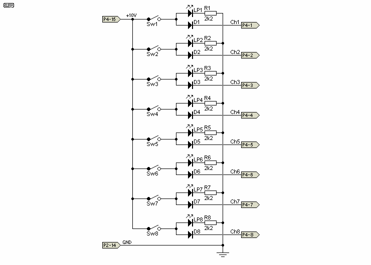
In the main console drawing, there is a row of switches on the left hand side. These are used to switch any lamp fully on, and may be used on the main output bus (see below), or sent to a separate Dim-Rak 8 unit as shown earlier for a full system. While the circuitry for a row of switches is hardly challenging, it is included to complete the project.

Figure 8 - Switched Output Circuit
There is a LED indicator for each output, and this adds an additional small load to the 10V regulator. Each LED draws around 4mA, so if all switches were on, that represents an extra 32mA from the 10V supply. The revised version will handle that with ease.
It is important to realise that the general limits imposed by outlet current ratings mean that you must be very careful not to exceed the maximum current. If you were to use 8 x 1000W lamps, then you would normally only be able to switch on two at any one time. It is more likely that the switched outputs would be used for low power lights (including perhaps specialty lighting such as small lasers, mirror balls and similar relatively low current devices).
| Overview | Channels & S2L | Chaser & Strobe | Power Control | Connections | Miscellaneous |
|---|
 Main Index
 Projects Index