
|
| Elliott Sound Products | Project 62-A |
There is a standard show lighting protocol for analogue dimmers which I have followed during the design and development of the LX-800. There is nothing too fancy or complex about the circuit. It can all be broken down into sections: the master faders, the channel faders, the sound to light filters and so on. With an eight channel system, there are obviously eight very similar sections making up the console electronics.
 ESTA E1.3, Entertainment Technology - Lighting Control System - 0 to 10V Analog Control Protocol, Draft 9 June 1997 (CP/97-1003r1) describes also that controllers and output devices shall be provided with a blocking diode (or similar circuit) such that each output presents an open circuit to any source voltage of more than itself. The blocking diodes allow multiple controllers or outputs to be paralleled to control the same dimmers or receivers on a "highest takes precedence" basis. The LX-800 conforms to the standard, in its current draft. All outputs in the system are either an analogue control voltage (variable between 0 and 10V) or a 10V pulse, routed through blocking diodes.
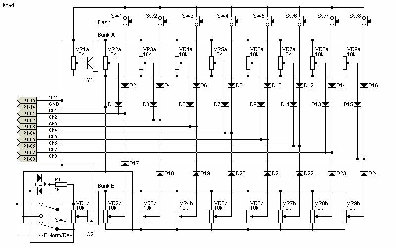
The circuit contains eight slide controls per bank, with a master fader controlling each bank. Having two banks of controls, each with its own master fader gives a great deal of flexibility to the finished article. One lighting state can be set up on Bank A, another (next scene or next song) on the Bank B. Make Bank A active by bringing up the master. At the end of the scene, reduce A and increase B and a smooth transition between lighting states is realised. A switch reverses the Bank B master so that maximum output occurs at the bottom of its travel and minimum at the top. By moving both masters together, very smooth transitions can be effected.
Each channel has a flash button associated with it that will bring its channel to maximum brightness regardless of the position of the channel fader. Useful for simple effects.

Figure 1 - Main Fader Bank Circuit
The faders and flash buttons are wired as shown in Figure 1, and although it looks complex, it is just repetitive. The diodes isolate each section, and provide the "precedence" function, where whatever fader is at the higher level takes precedence. Note that the master faders control the voltage supplied to all the others in each bank. The bi-colour LED is used to show if the B-Group is switched to normal or reverse operation.
NOTE: For all schematics on this page, diodes are all 1N914 or 1N4148. Transistors are BC549 or similar (e.g. 2N2222A) and resistors are all 1/4W.
P1 is the main output for the fader sections, and connects to the dimmer rack via S1 on the rear panel.
Included in this section is the 8-channel sound to light converter. If you've ever seen a 3 or 4 channel system in operation, then this one with 8 channels will blow you away! When you get it built, do yourself a favour - play Queen's "Bohemian Rhapsody" through it, with the volume high and the house lights low - Wow!
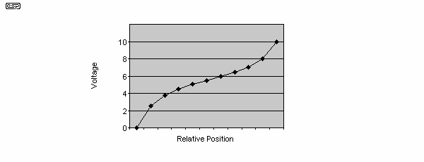
A reader suggested an improvement to the faders that will improve their apparent linearity dramatically. Simply by adding a pair of resistors to each fader, the "S" curve is produced. This approximates our eyes' response to the lamp filament voltage, as well as the actual light output at various voltages.

Figure 1a - S-Curve
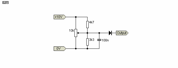
To obtain this curve requires the addition of two resistors to each fader as shown in Figure 1b. The downside of this is that the loading on the power supply is increased. In the original configuration, each pot draws a maximum of 1mA with the master fader at full-on position. This new circuit draws considerably more, and the supply has been upgraded to suit.

Figure 1b - Added Resistors to Obtain S-Curve
The revised version of the 10V regulator shown on the Power Control page will accommodate the additional loading. Each pot will draw 3mA worst case, which is when the pot is at maximum setting. The two banks of faders will have a total current draw of over 60mA with this circuit, as opposed to about 22mA for the original. The capacitor shown is optional - feel free to omit it to minimise component count.
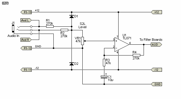
The S2L section consists of an audio buffer section at the input which feeds eight filters to split the audio spectrum into eight channels. The lowest frequency is filtered through a low-pass filter with no low-end consideration. It is designed to cut off at its high side. Six bandpass filters follow, then a high pass for the highest frequencies - again, no care has been taken to limit the upper frequencies. The input buffer stage is shown in Figure 2, and is designed for high level input. VR1 allows the sensitivity of the S2L system to be set as desired.

Figure 2 - Sound To Light Input Section
The next stage has the high and low pass filters (Channel 1 and 8 respectively). The circuit for this is shown below.

Figure 3 - High and Low Pass Filters
Finally, there are 3 dual sections for the 6 midrange frequencies. The capacitor values and connector pinouts are shown in the table.

Figure 4 - Midrange Filters (6 in all)
Each of the bandpass filters has a different frequency, which is determined by the capacitors. The table shows the channel number, capacitor values and connector pin number. Values in brackets are for the second section, since each filter has two sections allowing the use of dual opamps.
All diodes are 1N914, 1N4148 or similar
| Channel | C1, C2, (C4, C5) | Frequency (Hz) | Connector Pin |
| 2 | 18nF | 110 | P3-x = P3-2 |
| 3 | (6.8nF) | 300 | P3-y = P3-3 |
| 4 | 3.3nF | 605 | P3-x = P3-4 |
| 5 | (1.5nF) | 1,300 | P3-y = P3-5 |
| 6 | 680pF | 2,930 | P3-x = P3-6 |
| 7 | (270pF) | 7,450 | P3-y = P3-7 |
The schematics and table show where the S2L outputs connect to the rear-panel connector (P3) and how the link cable will connect to the dimmer section (connect to P2) for the precedence protocol. The outputs from the dimmers terminate at the rear-panel socket P1.
If you want individual power boxes, then the dimmers from (P1) will connect to one DIM-RAK 8 and the S2L, through (P3), will connect to another.
| Overview | Channels & S2L | Strobe & Chaser | Power Control | Connections | Miscellaneous |
|---|
 Main Index
 Projects Index