
|
| Elliott Sound Products | Project 62-D |
| WARNING: It is ESSENTIAL that all fusing specifications are followed precisely. Because of its capabilities, the LX 800 CAN overload the local mains supply found in small clubs and theatres. Rather have the fuse blow than the whole darned place go into instantaneous blackout! |
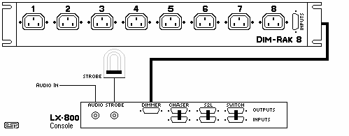
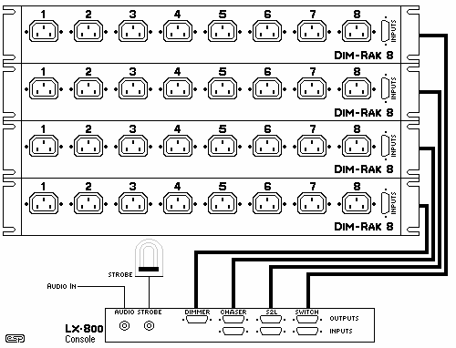
These are the basic connection diagrams of the LX-800. Start with a minimum system configuration and build it up as budget allows. Remember that the precedence protocol will work on those sections that do not have their own DIM-RAK 8s. Just link the in-out 15-pin connectors on the rear panel, as shown below.
 |
The drawing on the left shows a minimal system. In fact, the audio feed and strobe head don't even have to be there. A console and a DIM-RAK 8 are all that are required for a simple lighting system. Because of the precedence system used, every function on the console will work with only a single DIM-RAK 8. The outputs from the various functions are bridged with the cables shown, so that everything is connected. With a single dimmer as shown, the maximum load is 10A (2.3kW for 230V mains). This means that each dimmer circuit will be loaded with up to 250W or so, and with all channels on full power the maximum load will be 2kW. Obviously, some channels will most likely be loaded more than others, but provided the maximum is less than 2.3kW all loads will be within the mains circuit's ratings. Note that the regulations and maximum power will vary from country to country, so make corrections as needed. |
 |
The maximum system configuration looks like this. Each section connects to its own DIM-RAK 8. Obviously, the maximum power rating of the incoming supply must NOT be exceeded, but this diagram shows just how versatile the LX-800 can be. As described in the previous section, each DIM-RAK unit should have a 10A fuse, allowing a maximum load of 2,300W (2.3kW) for all channels combined. The total of all channel loads on each dimmer must be no more than 10A, otherwise with the channel outputs all at maximum you will blow the fuse. If multiple DIM-RAK 8 units are used, they should be connected to separate mains circuits, or the maximum circuit rating may be exceeded. Any variation between the minimum and maximum can be used, so 2 or 3 DIM-RAK 8 units can be connected to the panel, and the additional console functions bridged to the master bus as shown above. This gives very good flexibility to get the most functions from the least equipment. There is no real reason that the DIM-RAK 8 units cannot be spread across the 3 phases usually available - this distributes the load and allows greater overall power from the system. |
The connector designations are as follows ...
| Fader Banks (A and B) | P1 |
| Chaser | P2 |
| Sound to Light (S2L) | P3 |
| Switched Outputs | P4 |
| Master Bus | S1, S2, S3 |
All cables are wired conventionally. There is a male (plug) on one end, and a female (socket) at the other. DB15 connectors are used throughout, with pin-1 (plug) wired to pin-1 (socket) in all cases. Cables are interchangeable - all connections are wired in all cables.
While it may be tempting to take short cuts to save wiring, this will only come back to bite you when the system is in use. By making all cables the same, this ensures that any cable can be used in any location without problems.
Each cable will connect (and join) the +10V, +12V, -12V and 0V (earth/ground) from each dimmer unit. While this does not automatically mean that the power supplies will current-share perfectly, the paralleled connections do mean that there will always be plenty of 'juice' available, even if one supply is unable to cope - the others will fill the shortfall.
| Overview | Channels & S2L | Strobe & Chaser | Power Control | Connections | Miscellaneous |
|---|
 Main Index
 Projects Index