

|
| Elliott Sound Products | Project 205 |
 | Please Note: PCBs are available for this project (Project 66, Project 94 and Project 87B). |
Using PCBs already available, this project shows how easy it is to build a high quality mixer suitable for dynamic microphones, keyboards or a mixture of mic and line inputs. This isn't a toy, but a serious mixer that can be expanded as required to have as many channels as you need. I would not go beyond eight channels though, as it may become noisy. You can substitute a quieter opamp for the NE5532 specified, but it will give a very good account of itself as shown.
Small mixers are often all that's needed for an individual or small group, and there are countless examples on the market. While there are certainly some that appear to be genuine bargains, the problems will surface in five years or so if something fails. Those offered now use SMD (surface mount devices) throughout, and should something fail that generally means you have to buy a new one. Most are not designed to be serviced, and once 'spare' PCBs are no longer available, all you can do is recycle it. The other benefit of the DIY approach is that you can customise it to your needs.
If you need to accommodate a vocal group or have a small choir in need of a little reinforcement, this project has everything you need. It will mix a small multi-vocal performance into either one or two output channels. The mixer has four mic preamps (optionally with 48 V phantom power), making it possible to use dynamic or condenser microphones. The EQ is basic (bass + treble), but it works very well and can be set for the 'sound' that you want. Optionally, you can add RCA CD/Tape inputs (assignable to main mix or control room/phones outputs) and record your performance to an outboard recording device via RCA outputs.
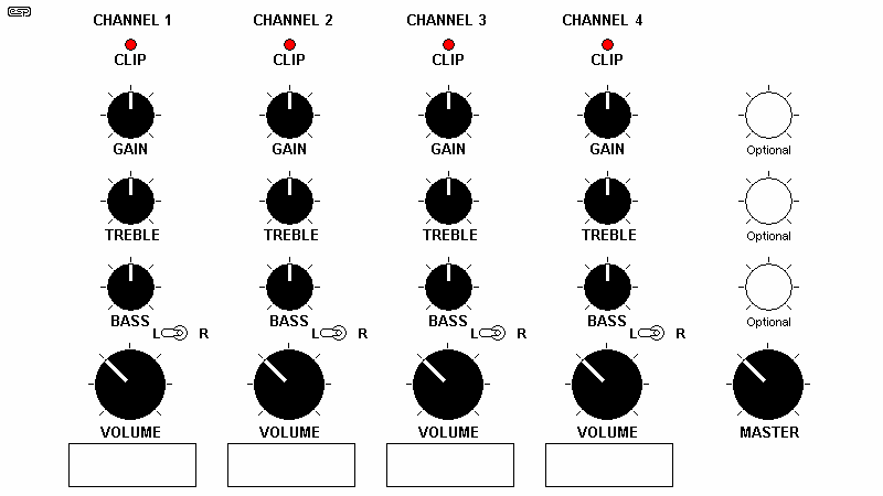
Typical Mixer Layout
A four-channel mixer could follow the layout shown. Each channel has gain, tone and volume controls (the latter is normally a fader, but slide pots are too big for a small mixer, and aren't worth the trouble). Optionally you can add a switch to select whether the signal goes to the left or right output channel (for a stereo mixer). Alternatively, you can use a pan control (roughly the equivalent of a balance control on a hi-fi system). The method of achieving this is shown below. Most small mixers are mono, but you have many choices when you build one yourself.
The mic/ line inputs are fully balanced, and based on the tried and proven Project 66 circuit. This is a balanced input, low noise mic preamp, with noise performance second to none. The gain is adjustable as a front panel preset, so that signal levels can be accommodated from as low as 5mV RMS. The gain is adjustable, and the maximum recommended input level (minimum gain) is +10dBV (3.16V RMS).
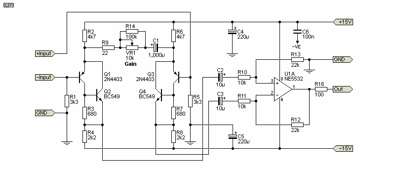
Figure 1 - P66 Dual Mic Preamp (One Channel Shown)
There is a small modification to the standard version of the P66 mic preamp. The gain of the opamp stage has been reduced so the preamp can handle +10dBV (3.16V RMS) without overload or the need for an attenuator pad. This does reduce the maximum gain available to 46dB (200 times), but for performance work this should never be a problem. Most people imagine that the output from a dynamic microphone is only a couple of millivolts, but most singers will exceed that easily. Even with the reduced gain, the sensitivity at full gain is 5mV for 1V (0dBV) output.
The next two sections use the Project 94 'universal' preamp/ mixer. There are some changes to that as well, primarily aimed at reducing the noise level. Most resistor values have been reduced, and in the tone control section, the capacitor values have been increased. The PCB doesn't require any modifications, but C103/203 may be a bit bigger than the space allowed, and might need a small kink in the leads so they will fit. Use 63V polyester caps - 100V types will be too large. Of course, you can use the original values shown in the P94 project, and while it will be a little noisier, it's doubtful that it will cause any problems.
Following the mic preamps, there's a level control, followed by a gain stage (6dB). This can be converted to unity gain by omitting R104/204, and replacing R105/205 with a wire link. This is not likely to be needed though, unless all of your signal sources are more than 0dBV (1V RMS). Only one channel is shown below, and the other is identical.
To build a full 4-channel mixer (four mic inputs, each with tone control) you'll need two P94 boards to get four sets of tone controls. This may not be necessary for your needs, in which case a pair of mic inputs can be equipped with tone controls and the other two direct into the mixing stage. If you need extra unbalanced line level inputs, you may need another PCB, but each P94 board has provision for four inputs to the mixer stage for each channel. Additional inputs can be provided without the second PCB, but they won't have the gain provided by U1A/B. They won't have individual tone controls either, but in a well set up system that may not be a problem.
You might even decide that all channels will share a single set of tone controls (assuming a mono system), or you can use dual-gang pots to provide a stereo output with tone controls. Figure 2 shows the configuration for the first (input) half of the P94 board.
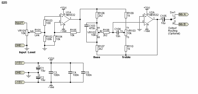
Figure 2 - Gain Stage & Tone Controls (One Channel Shown)
VR101/201 are not catered for on the P94 PCB, but they are simply wired between the mic preamp's output and the 'InA' point on the P94 board. Each of the small designators (e.g. B1, T1, etc.) is a termination point on the board, and all are marked with the same designations shown on the schematic.
The routing switch lets you select an output channel for each input. The output of each is mono, and if you want a stereo output, the switch would be replaced by a pan pot. This is common in stage mixers, but isn't so popular in small mixers.

Figure 3 - Pan Pot Option
The drawing above shows how to wire a pan pot. This lets you 'position' the signal source either to the left channel (Mix A), right channel (Mix B) or somewhere in between. When the pot is centred, the output is mono, with an equal signal on both outputs. The pan pot introduces a loss of 6dB when the pan pot is centred, or 4.3dB when set fully Left or Right. This loss is easily recovered by using a little more gain in the mixing stage (increase that value of R115/215 in Figure 3).
The pan pot and associated resistors are shown as R19x (R29x for the second channel). That's because they are not provided for on the PCB, and the designators are well beyond any on the PCBs. This saves any confusion that may otherwise result.
You can omit any input resistors that aren't used. For example, if you are using a tone control section for each mic preamp, you'll use either two inputs on Channel 1 and two on Channel 2, or all may be combined into a single channel. The P94 is an extremely versatile board, and many different configurations are possible. In many cases, if you use two boards, the mixer stages won't be needed on the second PCB, depending on how you configure the system. Unused parts of the circuit can be omitted, outputs from the second board can be mixed by the first board, or you can have multiple outputs. The following circuitry is in the second (output) half of the P94 board.
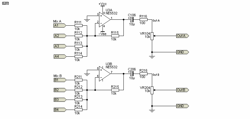
Figure 4 - Mixer & Outputs (Both Channels)
If you don't need balanced outputs, the input sections of one board can be used to drive low impedance outputs. The possibilities are (almost) endless, so you need to decide on the configuration you need, and wire the sections appropriately. The picture in Figure 1 is intended as an example - you may decide to do something quite different.
It's up to the constructor to decide if the Master section is stereo or mono. If it's mono, there's no requirement for switches to select the channel, and of course pan pots aren't needed either. Because the project is made up using available PCBs, it's as flexible as you need it to be for your application.
If you don't need balanced outputs, you can use the signal directly from the Master pots (VR104/204). Worst case output impedance is about 2.5kΩ, and that can drive a cable with a capacitance of up to 2nF without high frequency loss. With more-or-less typical shielded cable, that means that you can use up to 3 metres (about 10') of cable. If you need to run longer distances, I suggest that you use a balanced output.
To include balanced outputs, P87B is added. This not only buffers the output from the 'master' volume control, but provides a true balanced output. The PCB is available for this, and is another tried and proven design. Output impedance is 200 ohms, and the complete circuit of the P87B is shown below. While it's optional, I would recommend that it be included. If the outputs (unbalanced) are taken from the master volume pot(s), the worst-case output impedance is 2.5kΩ. This won't cause any problems if the amplifiers is close by, but if the mixer is any distance from the amps (or the FOH desk), you need buffers as a minimum, and ideally balanced outputs. The balanced outputs can be used as single-ended (unbalanced), simply by using the '+Out' signal and ground (do not ground the '-Out' output - leave it disconnected when using unbalanced outputs).
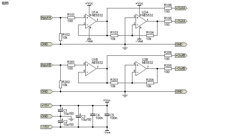
Figure 5 - Optional Balanced Outputs (Both Channels)
There's nothing new of different about it, it simply does its job. If you need particularly high common-mode rejection, all the 10k resistors should be either 0.1% tolerance, or selected from 1% resistors to be within 10 ohms of each other. The exact value isn't important, only that they need to be closely matched. If you use 1% resistors, the worst case CMRR (common-mode rejection ratio) is 40dB. It may not seem to be wonderful, but in reality it's usually more than enough.
Unfortunately, this is the one circuit for which there is no PCB. That may change though, as it's a very useful circuit and can be applied to any preamp or power amp. It's especially useful for mic preamps, as it can be difficult to know if transients are causing momentary clipping. With the values shown below, the LED will come on if the signal level exceeds ±5V (+14dBV). It can be changed easily simply by varying the value of R2. If it's 10k, the detection level is ±10V (+20dBV). This is too high for the mic pre though, and I suggest that the values shown be used.
This is a simplified version of the circuit described in Project 146, with the only significant difference being the elimination of a trimpot. The range is correct 'as-is', and there's no point making it adjustable. There's also no requirement for input protection diodes, because the input level can't exceed the supply rails. The circuit will respond to a signal outside the positive or negative limit, so it can be considered full-wave. Many clipping detectors are only half wave, and highly asymmetrical signals can cause clipping that isn't detected reliably.
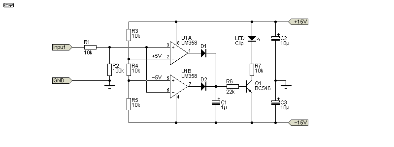
Figure 6 - Clipping Indicator
The two LM358 opamps are configured as a window comparator. As long as the input signal remains within the 'window' (less than +5V and greater than -5V) the LED remains off. Even a brief transgression will charge C1, which is used to 'stretch' the pulse so it lasts long enough to be seen. Ideally. the LED will be a high-brightness type, and that may allow you to increase the value of R7. None of the switching current passes through the ground connection, so it shouldn't create any noises when the LED turns on or off. The LM358 is specified because it's output can fall to the negative supply, preventing the LED from drawing any current when the signal is within the allowable range.
The diodes are 1N4148 or similar - any small signal diode capable of handling 30V will work. C1 should be rated for 50V, although 35V will be fine if you have them on hand. Several indicators can use the same reference voltages, so R3, R4 and R5 can be shared across multiple clipping detectors (although if a PCB is made available, it will be dual channel).
I suggest the Project 05 supply, and depending on the opamps used, you will almost certainly need to use heatsinks for the regulators. The transformer (15-0-15V, 30VA or so) should ideally be in a separate enclosure, along with the bridge rectifier and a pair of filter caps. This keeps the noise on the leads from the supply to the mixer to a minimum, and prevents a likely large voltage drop across the leads if they were to carry the 'raw' AC.
This is a fairly adventurous project, but not in the same league as the one published as Project 30. This one is easily built using available PCBs (and there may be a board available shortly for the clipping indicator - COVID-19 permitting of course). There is still a significant cost for all the pots, but that depends on whether you include tone controls and/ or pan pots for each input. We know that small mixers can be purchased for not much money, but they will be all SMD internally, and it's likely that if they fail outside the pitiful warranty period usually offered, the mixer is just scrap metal.
The advantage of building your own is that you can customise it. If you find that you need phantom power, that can be added. Too much (or too little) gain? Not a problem, as you can change that to suit your needs. Everything can be customised, including the tone control response, the output configuration (mono, stereo, or even a mix of the two). Unfortunately, there's quite a bit of wiring for the pots and between boards, but none of it is too daunting, and every part of the mixer can be repaired if something goes wrong.
Compare that with those you can buy. The circuitry will almost certainly be SMD throughout, often with custom pots that you can't replace. Not only is repair extremely difficult, but customisation will usually not be possible. You can only use it the way it was designed for, and making changes is next to impossible.
 Main Index
 Projects Index