
|
| Elliott Sound Products | Project 94 |
 Please Note: PCBs are available for this project (Rev-B now shipping). Click the image for details.
I have had a great many enquiries about small mixers, and this project should suit the needs of anyone who needs a very basic mixing unit. It has an input buffer, tone controls, and a 4 input mixing amplifier. I have called it 'universal' since the same PCB can be used for many applications requiring basic amplifier modules. It can be used as a hi-fi preamp, mixer, general purpose amplifier/ tone control building block, or you may find other applications just waiting for something like this.
The P94 is a recommended board for use in a reverb system. P113 is configured to drive the reverb tank and recover the signal, and all tone control/ mixing is performed using the P94. This allows for far more comprehensive control of the reverb signal.
The list of configurations possible is so broad as to make it difficult to cover them all. The secure site shows several configurations for the PCB, from the basic functionality described, right through to using it as a balanced line driver. The opamps used depend on you - The drawings show either TL072 or NE5532, but any dual opamp will be fine, depending on your budget and expectations. The OPA2134 is also suitable, and may be preferred because it has virtually zero input current so pots won't get noisy (the NE5532 has enough input current to cause problems in some cases).
The configurations are extensive despite the simplicity, since various other projects can be used as the front end. For example, using 4 of the P94 PCBs would allow you to have two stereo line inputs (direct via pots), a stereo phono input (using P06) and a stereo mic input (with a P66 board), each with its own level and tone controls. Please see Project 94A for alternate wiring schemes you can use that will suit many applications.
A stereo master volume control then lets you set the overall level, and the individual channel levels are set using their respective level controls.
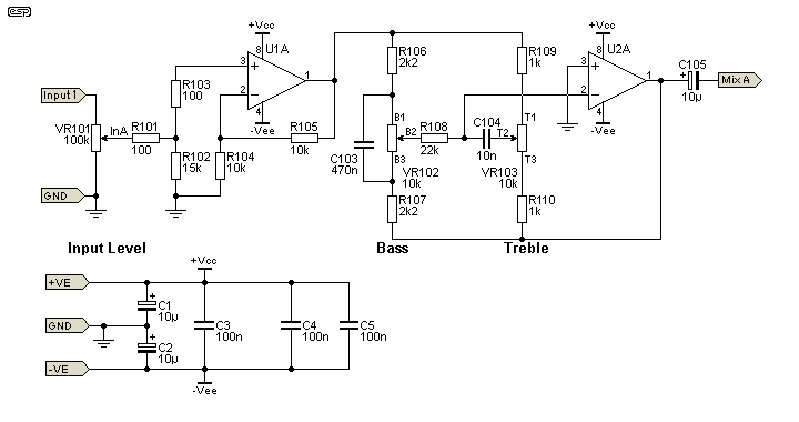
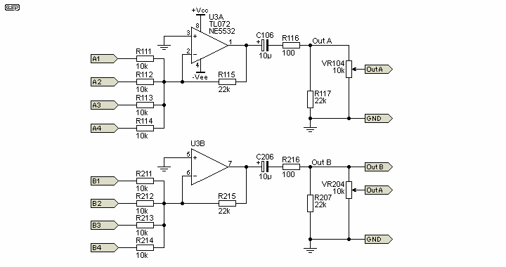
The circuit is very simple, and the PCB is nice and small (approx 50 x 75 mm). The idea is that one PCB would be wired with all components (Figure 1 and Figure 2), while the others only use the section shown in Figure 1. You can select the inputs you need, and add the appropriate input circuits, such as phono preamps, mic preamps, etc. Indeed, the range of uses is determined more by imagination than any 'limitations' in the circuitry itself.
Note that none of the pots are mounted on the PCB. Everyone (including me) hates running wires, but using PCB mount pots would seriously reduce the flexibility of the board. All pots need to be dual-gang for stereo, or single-gang if it's used as a small mixer where individual control of each channel is required. As noted below, pots are all linear, and 10k is suggested for all of them.
The first stage (U1) is a buffer, but provides a gain of 2 (6dB) as shown. The gain is easily changed by changing the value of R104 (and R204 in the 'B' Channel) - a higher value gives less gain, and vice versa. I don't recommend that the gain be increased beyond about 4 times (12dB), or DC offset may become a problem with some opamps. A value of 3k3 (3.3k) for R104/204 will give a stage gain of 4.03 (12.1dB) which should be more than enough. An external microphone preamp is a must if very low level signals are intended.
The input impedance is set by R102/202, and as shown it's 15k. This makes a 100k linear input pot behave like a log pot, but this is entirely optional. If you were to use a 10k log pot at the input, R102/202 should be increased to ~22k. If you need higher impedance, I suggest a TL072 for U1, which will allow up to 1MΩ or more without excessive DC offset.

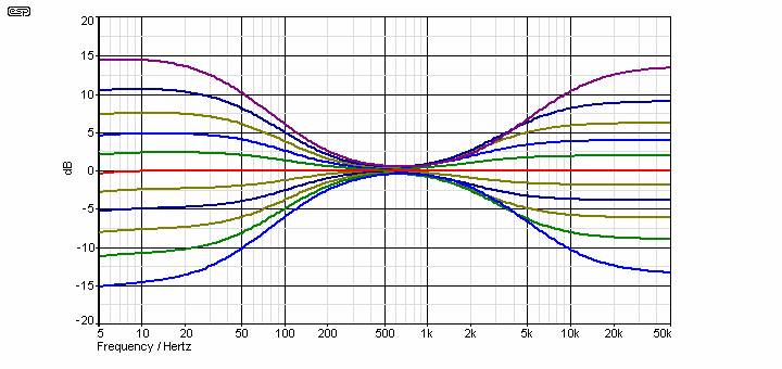
The second stage is a standard Baxandall feedback tone control, and will give an almost dead flat frequency response with the controls in the centre position. For stereo, use dual pots all round, but for mono (or two mixer channels), single pots will be needed. The tone control response curves are shown in Figure 3. The small markings on the pots (e.g. B1, B2 and B3) are references to the PCB connections.

The mixer is the common 'virtual earth' mixing amplifier, and there is nothing special about it. Note that it is inverting, which complements the tone controls (also inverting) so the absolute signal polarity is maintained. As shown, the mixer has a gain of a little over two times, and again this can easily be changed. Making R115/215 10k sets the gain at -1 (i.e. unity, but inverted). Note that R117/217 are now mounted on the board (they were previously off-board).
Worst case output impedance is 2.5k with a 10k pot, so this unit is not suitable for driving long signal leads. VR104/204 can be reduced in value if you want, but if good quality low capacitance leads are used, I doubt that you'll have any problems. If you need to have a balanced output, use the P87B balanced line driver. If you expect long cables but don't need a balanced output, you can add a simple opamp buffer stage, and remember to include a 100 ohm resistor in series with the output to prevent opamp oscillation.
All potentiometers are linear taper. The resistor values are selected to give a quasi-log law as described in Project 01 for gain (volume) controls.

Figure 3 shows the frequency response with the controls at 10% intervals. The centre frequency is deliberately set lower than the 'industry standard' 1kHz, which (IMO) is an extraordinarily non-sensible place to set the bass turnover frequency. You will notice that there is a small 'flat' section, between 500Hz and a little under 1kHz. Bass response may be changed by using a different value for C103/203 (higher value, lower frequency), and likewise C104/204 control the high frequency point (lower value, higher frequency). I expect that most users will find the values to their liking as shown, but it can be changed quite easily.
You should use 10k pots for tone controls if possible - resistor and capacitor values are then as shown. Other combinations will also work, and you just scale the resistors and caps to suit. If the pot values are increased, you simply reduce capacitors to scale, and increase the fixed-value resistors likewise. There's nothing to be gained by doing so, but you may be able to use pots you already have.

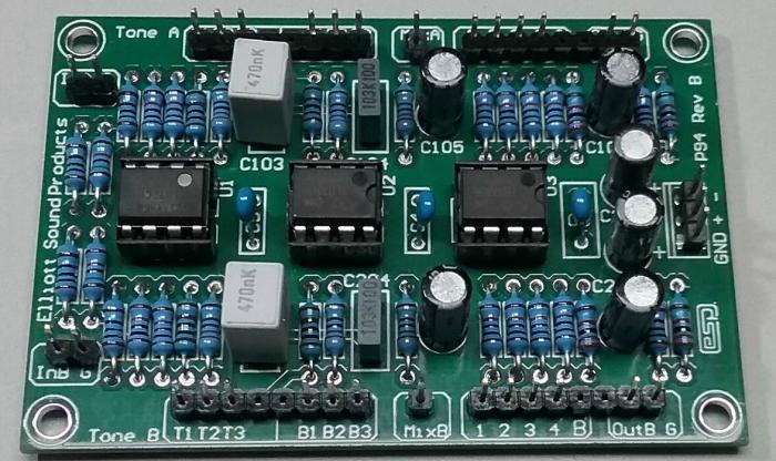
The photo of the PCB shows the standard preamp when fully assembled. Unused mixing resistors may be omitted. This is a perfectly valid option for normal use. The Revision-B board is double-sided, and has a ground-plane on the component side. There are few differences, but I have revised resistor values in a few places. The tone control pinouts are now in order - a small change but it makes errors less likely when wiring the pots.
If the ESP board is used, construction is very easy. It is small, but laid out very logically so it is easy to construct. No pots are mounted on the PCB - not because I like running wires (and I don't expect you do either) but because this gives you far greater flexibility for your version of the project. If I designed the board with the pots, then you would have to use the same type as I designed for, and the same spacings and layout. This is very restricting - especially if you can't get (or don't want to use) the same type of pot.
The power supply may be from ±9V (for portable use), or ±15V for use with the P05 power supply. Any dual supply may be used, so if you have one already, it may be used as long as the voltage is between ±9V and ±15V. Higher or lower voltages are not recommended, although some opamps will work reliably with lower voltages. Feel free to experiment as required.
The circuit will typically be fitted with TL072 opamps, but you may use anything you like (they must be an industry standard dual through-hole opamp though). Suitable devices include LM4562, OPA2134, RC4558 or NE5532. Feel free to use your favourite opamp if you have one, but I specifically recommend that you do not use LM833 types, as they have a tendency to be unstable in many circuits. The LM358 is also not recommended, as it has significant crossover distortion (one of the very few opamps with that problem).
 |
The standard pinout for a dual opamp is shown on the left. If the opamps are installed backwards, they will almost certainly fail, so be
careful. The suggested TL072 opamps will be quite satisfactory for most work, but if you prefer to use ultra low noise or wide bandwidth devices, that choice is yours. |
Remember that the supply earth (ground) must be connected! When powering up for the first time, use 100 ohm or 560 ohm 'safety' resistors in series with each supply to limit the current - this will prevent (most) damage if you have made a mistake in the wiring. Remember that if you purchase the PCB, full construction details are provided, and there's some additional information available as well.
 Main Index Main Index
 Projects Index Projects Index
|