
|
| Elliott Sound Products | Project 94A |
 Please Note: PCBs are available for this project. Click the image for details.
The standard version of the P94 has been quite popular over the years, and is a very versatile unit. Based on a number of queries since it was first published, this article shows just how versatile it is. See Project 94 for the original article, which has further circuit descriptions, tone control frequency response curves, etc.
The PCB has two sections - an input stage and a virtual earth mixer. In this version, the roles of the two are simply reversed, with the input stage now forming a master tone control stage, and the mixer is a multi-channel input.
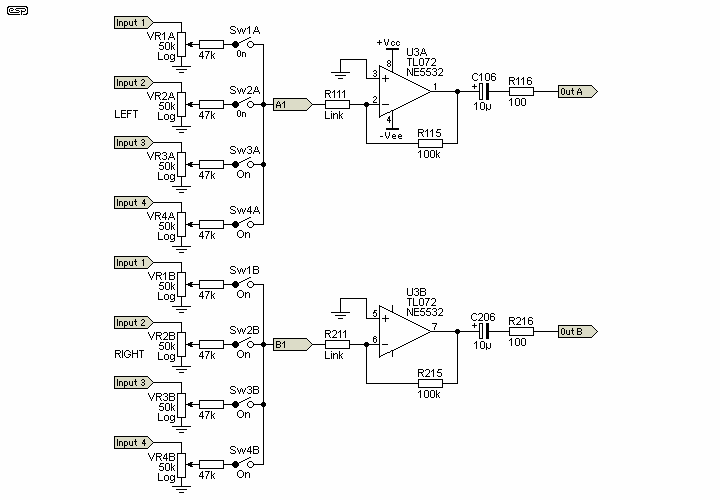
The circuit is very simple, and the standard P94 PCB is used. A single board can be used to mix from 2 to 10 inputs (only four are shown), and the switches let you switch off any channel that's not being used. This keeps noise to a minimum. Because a virtual earth mixer has a noise gain that is determined by the number of inputs, using switches to disable unused inputs keeps the noise as low as possible.
The circuit does function as a true mixer, with the ability to mix as many of the input sources as needed. There is no interaction between the individual level pots, so adjusting one will have no effect on the level of any of the other inputs.
The input stage (actually the second section on the PCB) has a maximum gain of 2 with the level control at maximum. This can be increased or decreased by changing the value of R115/215. A higher resistance gives higher gain and vice versa.

Figure 1 - Input Level, Switching and Mixer
The only change from the original schematic is the value of R115/215, and replacement of R111/211 with a link. The individual channel inputs are wired externally, which is repetitive but simple. Use of a PCB for this is ill advised because it would restrict the layout to that of the board.
The output of the mixer stage goes to a master volume control, which controls all channels simultaneously, while maintaining the relationship between mixed sources. A balance pot can be added if desired (see Project 01 for some ideas on this). Note that I have specified log pots (audio taper) for all inputs and the master for simplicity, and to maintain a respectable input impedance. As shown, the worst case input impedance of each channel input is about 20k.

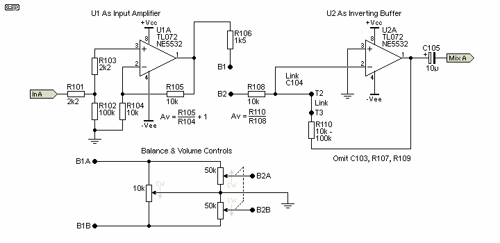
Figure 2 - Master Volume and Tone Controls
The master section is unchanged from the original P94 article. The input stage (based around U1) has a gain of 2 (6dB), allowing a total maximum gain of 4 times (12dB) with all controls at maximum. This can be increased in both the input mixer and the master section. To increase master gain, decrease R104/204. The gain of this stage is determined by ...
Av = ( R105 / R104 ) + 1 For example, using 10k and 4.7k respectively
Av = ( 10 / 4.7 ) + 1 = 2.13 + 1 = 3.13 = 10dB (close enough)
Note that because of the reversal of the circuit (the input stage is now the output stage), you must include external 100 ohm series resistors as shown at each output (Mix A and Mix B). If these are omitted, the opamp will oscillate if a shielded lead is attached (standard interconnect leads are always shielded).
Only the Left channel is shown. The right channel is identical, with resistor and capacitor designations as indicated on the circuit diagram.
In all other respects, refer to the Project 94 article. This shows tone control response and construction / test information, plus other data you will find useful to understand the circuit, and how it works. The reversal of the stages is easily followed because all PCB termination points have been shown as they appear.

Figure 3 - More Alternatives for Wiring
Above, you can see even more possibilities. The inverting section (around U2) can be used as shown above when tone controls are not needed. C104/204 are replaced with short links, and other parts as indicated are simply omitted. If the output of the mixer stage is connected back to the B2 terminal and U2 is configured for unity gain, the output is now balanced. You will have to add a 100 ohm resistor in series with the MixA (or MixB) outputs to ensure stability.
Since the board has so many possibilities, it's impossible to cover every eventuality, but it may be considered as two inverting amplifier stages (U2 and U3), plus a non-inverting stage (U1), and they can be individually connected however you wish. Although U2 is intended as a tone control stage, using it that way is only one option. There is absolutely no reason that the tone controls have to be for individual channels - that section may be used as the last stage if you wish, giving an overall (master) tone control circuit. In this case, remember to add a 100 ohm resistor at the MixA (and MixB) outputs.
 Main Index
 Projects Index