

|
| Elliott Sound Products | Project 146 |
The ESP website does have a couple of circuit for high performance overload detectors, but one is buried within the Project 30 mixer pages and is easily missed, and the other is in the Project 152 bass amp project. Since this is something that people seem to need (especially with mic preamps and the like), the circuit has been modified, physically tested, and is presented here. The modifications are primarily to allow the detection threshold to be adjusted to suit different applications.
There are also two additional circuits, both intended where you need a single overload detector for multiple points in a circuit (or to indicate an overload on either of two channels in a stereo system). An update has changed the switching so the LED is switched between the supply rails and doesn't include the system ground.
The circuit is shown below - it's very simple, but works well even with the most basic opamps. While it could have been made faster by limiting the opamp output swing with more diodes, doing so would increase complexity and introduce switching noise onto the input line. The aim of the circuit is to detect both positive and negative peaks - a great many peak/ overload detectors only work with one polarity. This is not really a good idea, because many (most) audio signals are asymmetrical, and detecting only one polarity could mean that some signals could be clipping without you realising that it's happening.
Another requirement is that the circuit can be connected to high or low impedance circuits without creating a non-linear load that causes distortion. This is especially true with high impedance circuits, because any non-linearity in the detector is directly reflected back to the source. An overload indicator that creates distortion in the source circuit is hardly useful.
Although shown here using ±15V supplies, these circuits will all work fine with other supply voltages. The detection thresholds are set from the supply rails, and the ratios remain the same regardless of supply voltage. Only the LED series limiting resistor will need to be changed in order to maintain a useable current at reduced voltage. For example, with ±5V supplies, you might reduce the LED series resistor to around 820Ω.
The circuit diagram is shown in Figure 1, and although shown with an LM358 opamp, you can use TL072, 1458, 4558 or any other common (cheap) dual opamp. While you can also use expensive high-performance opamps, there is no reason to do so - the circuit only lights an LED. The biggest advantage of the LM358 is that the output can swing to the negative supply rail, so there is no chance of the LED being on all the time. For other opamps, it will be necessary to reduce the value of the 10k resistor from base to emitter on Q1.
Where very high impedance is needed, the TL072 is suggested because its input bias current is very low, minimising errors caused by the input current. This is rarely necessary.
Despite the simplicity, the circuit works very well. If used with a mic preamp or similar, VR1 (trimpot) will allow you to set the peak voltage where the LED will come on. With VR1 at maximum, the detection voltage is about 10.7V, so there is almost no headroom before the signal clips. Normally, I'd expect VR1 to be set to roughly 1/2 resistance, which provides a detection threshold of ±8.3V. This is about the maximum you'd normally use for a circuit operating with ±15V supplies. Setting VR1 to lower resistance reduces the detection threshold voltage. At a 10% resistance setting (5k) the detection threshold is ±3V. If desired, a fixed resistor can be used instead of the trimpot.
U1A and U1B form what's known as a 'window comparator'. Provided the signal voltage remains within the boundary reference voltages at pins 2 and 5, the outputs remain at close to -15V. Should either pin 3 or pin 6 (which are joined) go above or below the reference voltage, the output of the corresponding opamp will swing high (close to +15V). C1 charges immediately via the diode, and the LED is turned on by Q1. After the transient has gone away, it takes time for C1 to discharge, so the LED remains on for long enough for you to see it. C1 cannot discharge back through the opamp outputs because of the diodes (typically 1N4148 or equivalent). The LED can be any colour you like, and the maximum LED current is about 6mA. This can be reduced by increasing the value of R6. Note that the circuit is mono - if you need to monitor a stereo signal you'll need two of them.
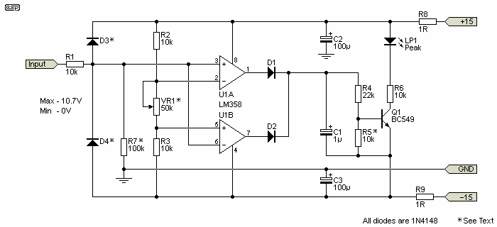
Figure 1 - Overload Indicator Schematic
There's not a lot to the circuit, and it is very economical to build. The input has an earth/ ground reference set by R7. If the input is connected to the output of an opamp or the connected circuit has an earth reference then R7 can be omitted. If the monitored circuit is capacitively coupled or has no earth reference, then the input must be connected to earth via a suitable resistance for R7. 100k will be suitable for most circuits, but for high impedance circuits (such as valve equipment) R7 can be up to 1MΩ.
Note: The LM358 opamp should not be substituted. It's used because its output can get to the negative supply voltage (within a few millivolts). Some CMOS opamps can do the same, but none has the required supply voltage (30V) and they are only available in SMD packages. R5 is not necessary if you use the LM358, but if you use anything else (TL072, 1458, 4558, etc.) then it must be included or the LED will remain on. A value of 10k will usually be sufficient, but for some opamps it may need to be a lower value.
There is one very important point that you must be aware of. Because the opamp comparators are fairly fast and there is a LED being switched on and off, the circuit can introduce noise via the supply lines (±15V). The LED and switching does not connect to the earth/ ground bus to minimise ground noise. For this reason, it is very important that all power wiring is returned directly to the power supply, and not daisy-chained from the supplies used for preamps. Supply decoupling is also desirable, as shown in the circuit diagram (R8, C2 and R9, C3). This keeps most of the noise within the circuit. I've shown R8 & R9 as 1Ω, but you can increase this a little if necessary. More than 2.7Ω may cause erratic operation. The other option is to use a separate zener regulated supply - it won't be perfect, but the circuit is only an indicator, and extreme accuracy isn't necessary.
If a large number of these circuits is used (in a multi-channel mixer for example), there's a lot to be said for including a secondary power supply to power all 'noisy' electronics. These include overload detectors (like this one) and metering amplifiers. If this is done, the power rail decoupling becomes less of an issue as long as all noisy supply busses are kept separated from other circuitry.
Note that the inputs must be protected from voltages outside the opamp supply rails. The optional diodes (D3 & D4) aren't needed if the circuit is monitoring audio circuitry operating from the same supply voltages, but are essential for anything else (valve equipment, power amplifiers, etc.). Where the input level will normally be (perhaps significantly) higher than the supply rails, the input should be provided via a pot (to allow adjustment) or a voltage divider. If a pot is used for the input signal, VR1 can be a fixed resistance.
For use with a fixed resistor, I suggest that VR1 is replaced by a resistor of 10k, which is quite suitable for many applications. With ±15V supplies, this sets the detection threshold to ±5V which is very convenient. The detection voltage for any value of resistor is determined by the following ...
V = Vcc / ( R2 / ( 0.5 × R ) + 1 ) ... so for example ...
V = 15 / ( 10k / ( 0.5 × 10k ) + 1 )
V = 15 / 3 = 5V
Vcc is the supply voltage, V is the detection threshold voltage (positive and negative) and R is the resistance used in place of VR1. In all cases, R2 and R3 are identical values, and there's no good reason to change from the 10k suggested. I leave it to the reader to determine how to reverse the formula so a resistance can be calculated from the desired threshold voltage.
To use the detector as a power amp clipping detector is simple enough, but be aware that unlike Project 23, it cannot compensate for supply rails that collapse with sustained high power. Therefore, it would normally be adjusted so that any signal greater than ~75% of the nominal supply voltage will cause the LED to come on. This is pessimistic, and in normal use it will be ok for the LED to flash occasionally. For an amplifier using ±35V supplies, you might want the detector to operate with any transient signal above 26V peak.
The input attenuator (between the power amp and clipping detector) could use the standard 10k resistor from the output, with a 2.2k resistor to earth (as shown below). This gives a threshold voltage of 27.7V - a little higher than the 75% suggested, but uses standard value resistors and will be quite satisfactory for normal use.
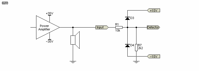
Figure 2 - Power Amplifier Attenuator Example
The above assumes that VR1 is replaced by a 10k fixed resistor, and as discussed, the detection threshold is ±27.7V (28V close enough). It will be quite alright if the LED flashes every so often - typically no more than once per second. This depends on the programme material of course. The occasional flash of the LED indicates that the amp is close to clipping, but there is still some headroom (about 1.5dB, which is the bare minimum).
For amplifiers with different supply rails (and therefore different power ratings), R7 can be adjusted to suit. This still assumes that VR1 is replaced by a fixed 10k resistor, so the detector will light the LED with any transient exceeding ±5V. Based on this, suitable values might be as follows ...
| Amp Power (8Ω) | Supply Voltage | R7 Value | Detect Voltage |
| 10 W | ±13 V | 12k | 9.2 V |
| 20 W | ±18 V | 5.9k | 13.5 V |
| 50 W | ±29 V | 3.0k | 21.7 V |
| 70 W | ±35 V | 2.3k | 26.7 V |
| 100 W | ±40 V | 2.0k | 30.0 V |
| 150 W | ±50 V | 1.5k | 38.3 V |
| 200 W | ±58 V | 1.3k | 43.5 V |
| 300 W | ±70 V | 1.1k | 50.5 V |
| 500 W | ±90 V | 800R | 67.5 V |
The resistor values are rounded to one decimal point, and there is some variation from the ideal. However, since the peak voltage was mainly based on 75% of the nominal supply voltage there is room for small errors without it causing a problem. Some of the values are not standard, and you may decide that using a trimpot in place of R7 is more appropriate. If you do this, select a pot that's around double the resistor value listed. For example, for a 100W/ 8Ω amplifier, a 5k trimpot would be suitable. For a 300W amp, use a 2k trimpot. With amps above 150W I recommend using a 1W resistor for R1 so that it is not stressed at all.
Overload detectors such as the one shown here can be a blessing or a curse. If you often use your system turned up pretty loud, then you'll likely be horrified to see that the clipping indicator LED is on much of the time. It's not at all uncommon for amplifiers to be clipping on transients, and most of the time the clipping is entirely inaudible. An overload indicator makes it very easy to see that's what is happening, and you could easily discover that when operated below clipping at all times, the amp isn't loud enough.
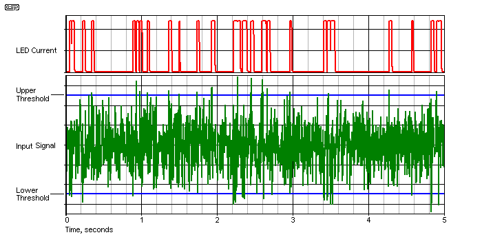
Figure 3 - Typical Operation With Noise Input
Figure 3 shows the simulated output (LED current in red), the noise signal in green, along with the upper and lower threshold voltages. Any time the input exceeds either threshold, the LED is turned on. This example is deliberately set so that there is plenty of activity. Although the diagram is a simulation, the waveforms are no different on an oscilloscope.
If you look very carefully, you will see that there are some excursions just on the thresholds that don't cause the LED to light. This is normal - the signal voltage needs to be at least a few millivolts greater than the threshold. While we might assume that 'fast' musical transients have a large high frequency component, this is usually not the case at all. The most common cause of amp overload is bass and midrange, especially when there is additional transient information 'riding' the bass or midrange waveform. The energy in music rolls off naturally above ~1.5-2kHz, and a super-fast detector serves no useful purpose.
All circuitry shown in this project is operated with an unbalanced input. Since it's intended to be used within a preamp or mixer case that's not a problem. It can also be used as an external unit, and will work fine even with balanced circuits. Because the input impedance is very high (when R7 is omitted), the circuit can monitor one of the two signal lines of a balanced interconnect, and because both usually have exactly the same voltage (just the polarity is reversed) if one line is close to clipping, then so is the other.
There are many instances where monitoring a single circuit isn't enough. For example you might want to check that several sections (or channels) of a circuit aren't clipping, from the input stage, through the equalisation sections, and also the final outputs. There are many configurations where the output might be well within limits, but earlier sections are either clipping or are dangerously close to it. Tone controls are a potential source of problems because there can be significant boost causing clipping, but if the volume control is after the tone controls and set low you may not realise.
The circuit shown will monitor as many or as few circuit sections as you like. There is no upper limit, so a single circuit can monitor multiple points in a multi-channel mixer. This may not be ideal, because you'd never know just where the problem was other than by disconnecting or muting each channel in turn. This is why most mixers have a peak/ clipping indicator on each channel. However, it's still useful, simply because it can monitor multiple signals. Note that while D1 may appear redundant, it ensures that both polarities have the same sensitivity. Without it, positive peaks would be detected at a lower voltage than negative peaks.
Most commercial equipment that has multi-stage clipping detection just use one polarity, so there's a single diode from each monitored point. This is simple and often sufficient, but highly asymmetrical signals can sometimes 'escape' detection. If you want to monitor both polarities it gets more complex. The circuit shown below will do it - you will need one resistor and a pair of diodes (1N4148 or similar) for each circuit point you wish to monitor. You'll run two 'sense buses' back to the detector as shown. The 2.2k resistors shown for each input are to isolate the circuit from diode switching distortion, and they can be omitted if you don't think you need them.
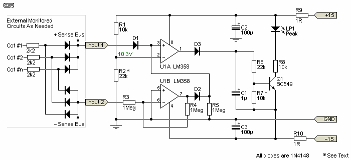
Figure 4 - Clipping Detector For Multiple Inputs
Positive excursions are monitored directly by the comparator (U1A). Negative excursions are inverted by U1B, and the output of that is diode isolated (with D2) and fed to the comparator. R2 is shown as 22k, and this sets the detection threshold to 10.3V plus two diode forward voltage drops (1.4V). Any signal peak greater than 11.7V (positive or negative, from any input) will trigger the comparator and cause the LED to flash.
To adjust the detection threshold, vary R2 as needed. For example, if you wanted to use the earlier example of ±5V to trigger the LED, R2 needs to be about 3.9k, and that sets the threshold voltage to ~4.2V plus two diode voltage drops, for a total of 5.6V close enough. Each input has the same number of diodes in series, and all will respond to the same peak levels. R2 can be replaced with a trimpot if desired, allowing you to set the trigger voltage to whatever you need. R7 is not required with the LM358, but is essential with other opamps that cannot reduce the output voltage to the negative supply.
Note that while this circuit can be used with a stereo power amplifier. you must include attenuators as described above and shown in Figure 2. Any input voltage above ±15V (or any other supply voltage you might use) may destroy the opamps. External attenuators are required for both inputs, and you may also require protection diodes (as shown in Figure 1).
Since single polarity detection is so common (it's used in countless mixers and the like), it's worthwhile showing how easy it is to achieve. While it is possible to dispense with the opamp, it has so many advantages that it's silly to try to get a predictable threshold without it. To get a reliable circuit will use more parts if you don't use an opamp.
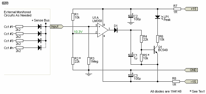
Figure 5 - Single Polarity Clipping Detector For Multiple Inputs
The circuit is very similar to that shown in Figure 4, but only one opamp is used. Although shown as 1/2 of a LM358 dual opamp, you can use a single opamp if you prefer. It's much simpler to connect to the various places you want to monitor because there's only a single bus needed. The 2.2k resistors are optional (as with the previous circuit).
Adjustment of the detection threshold is performed in the same way as the Figure 4 circuit, by changing the value of R2. Again, you can use a trimpot so it can be adjusted easily. R5 (same as R7 in Figure 4) can be omitted, but with the same caveats as the other circuits.
A PCB for this project will be available based on demand. It will have two channels, and each can be fixed (for example if used with a preamp) or variable for use with power amps and other high voltage sources. The inputs are DC coupled, and R1021/ 202 can be replaced with a pot (VR101/ 201) so the detection thresholds can be adjusted to suit the application. If used with a power amplifier, protection zeners are employed to ensure that the input stage isn't damaged. For high-power systems, R101/ 201 should be increased in value.
Zener diodes are used to ensure that excessive voltages aren't simply diverted to the supply rails, as is the case with the more 'traditional' approach of using diodes to the supply rails. Under extreme conditions, this can cause the supplies to rise above the safe operating voltage for opamps. It isn't something that happens often, but zener diodes ensure that it can't happen at all. The zeners can be omitted if the source is powered from the same supply voltage.

Figure 6 - Dual Clipping Detector (PCB Version)
With the values shown, the detection thresholds are ±5.5V (10k input resistor, 100k to ground), but this is easily changed. Mostly, it's not necessary, because ±5.5V is a sensible limit for 'low-level' circuitry. For power amplifiers, R101/ 201 should be increased to 22k, and this allows peak voltages up to ±70V (over 300W into 8Ω) to be handled with ease, using 0.25W resistors. Higher voltages are accommodated by increasing R101/ 201 further. The trimpot is essential of course, otherwise you can't set the voltage. You can calculate the respective values of R101/ 201 and R102/ 202, but inconvenient values are more likely than not.
The 10k trimpots let you set the trip voltage to anything you like. With 10k input resistors and a 10k pot, the minimum voltage that can be detected is ±10V (12.5W, 8Ω), so it's suitable for amps down to 15W. BTL amplifiers can also me monitored, but if they operate from a single supply, you'll need an external input capacitor to reject the DC component. The circuit has been designed for maximum possible flexibility, but it's a small PCB (61 × 37mm) and there's no space for input caps. Mostly, they are not necessary, as the circuit is designed to sense absolute voltages - including DC.
The reference voltages will almost always be symmetrical (R1 and R3 equal values). To change the references to ±2.1V (for example), simply change R2 from 10k to 3.3k. Avoid the temptation to increase the value of R2, as that may cause slight instability in the reference voltages. If you wish to use different opamps (such as 4558, 1458, TL072, etc.), R104/ 204 must be installed, or the LED will never turn off. These opamps cannot reduce their output voltage to zero, so the resistors are essential to ensure that the transistors can turn off (thus extinguishing the LEDs). Note that you cannot use NE5532 opamps, as they have protection diodes at their inputs, and the circuit will not function properly. This applies to any other opamp that uses input protection diodes as well.
The LED 'on' time can be extended by increasing C101/ 201. I wouldn't recommend more than 10µF as that will extend the 'on' time way too far. As shown, a short transient will turn on the LED for around 20ms - plenty of time to see it, and a very good indication of momentary transients.
For all of the circuits shown, be careful with supply and ground wiring. The circuit is designed to minimise ground current so it can't inject 'hostile' waveforms into the common ground bus (a few microamps at most), but it's not so easy to keep spike currents out of the supply lines. The current waveform is quite capable of causing audible noise, so ensure that the clipping detector has its own set of supply leads wired back to the output of the regulator board. Keep these leads well away from signal wiring, and consider using shielded dual-core cable to keep radiated noise to a minimum. Even though the selected opamps aren't fast, the transistor is fast, and will switch on in less than 100µs when the input threshold is exceeded.
To help minimise noise, use a high-brightness ('ultra-bright') LED (blue LEDs are generally the brightest, but are intrusive). Aim for a brightness of 100mcd (milli-candela) or more, and increase the value of R105/ 205 to get a comfortable brightness. With 10k as shown, LED current is about 2.7mA, and that's more than enough with a high-efficiency LED. You can also use a separate supply (such as P05-Mini) to ensure that the audio and indicator supplies can't interact. They can share the same transformer.
In some cases, you may need a signal detector, that shows when a signal is present above a preset threshold. This is easily done, simply by using a low value resistor for R2. With all other values remaining the same, a 33Ω resistor for R2 will allow the circuit to detect a signal above about 20mV RMS. If you need a higher detection threshold, use a higher value. The relationship is fairly linear when a low value is used, so 100Ω (for example) will set the detection threshold to around 60mV.
Feel free to experiment, and you can use a trimpot if you need to make the threshold adjustable. A 200Ω trimpot should suit most applications for a 'signal present' detector.
 Main Index
 Projects Index