
|
|
| Elliott Sound Products | Project 203 |
 | Please Note: PCBs will be available for this project shortly. This will be impacted by the current Coronavirus/ COVID-19 pandemic. |
This is a major update of the original Project 34 reverb system. It's not just for guitar or keyboards, you can use it for anything that you want. Spring reverb units are most commonly used in guitar amps, having been replaced by digital effects in most other areas. The circuitry will always be somewhat experimental, and may change quite dramatically depending on the type of spring reverb unit you can actually get your hands on. The PCB is designed (available soon) to accommodate most reverb tanks, with the optimum being those with a low impedance drive coil.
The tank I have is an Accutronics, but you might already have a tank or can get something different, so you will have to take measurements of the tank you have and/ or experiment to get the best performance and the sound you want. There aren't a great many options, and although you can almost certainly get a cheap unit made in Asia, you'll likely be disappointed. There's also another brand that's surfaced fairly recently (MOD), but I've not used one and know little about them.
Only a few of the possibilities are discussed here, but with a small amount of experimentation you should be able to tailor the reverb unit to your needs. I suggest that you read The Care & Feeding Of Reverb Tanks, as that has a great deal more information on the topic.
Since the P113 headphone amp is very easily modified for constant current drive, this used to be recommended because it works very well. However, wiring the two halves of the P113 board differently was somewhat clumsy in early boards, but is a great deal easier (and neater) with the Revision-A boards (see Project 211). The circuit shown here uses the same drive system, and has everything else that's needed for a complete reverb system. The circuit shown in Figure 2 is the latest incarnation of the reverb circuit. Unlike the others that are somewhat 'piecemeal', it's a complete reverb sub-system. It can be used in an effects loop, or stand-alone. The reverb signal level is adjustable. You can choose to mix reverb with the 'dry' (original) signal, or keep the reverb completely separate.
Note that to use current drive, the input transducer's connector must not be connected to the tank's chassis. Most versions of spring reverb tanks have this as an option, and it's very common. It should cause no difficulties, because these tanks are popular with hobbyists and guitar amp manufacturers alike.
The tank used for all tests is a 4AB3C1B - 8 ohms input, 2,250 ohms output, long delay. With an input current of 90mA (three times the suggested figure), it produced an output of 12-16mV when swept with a 150-4,500Hz tone. The output will be reduced proportionally if you use a lower drive current. At the suggested current of ~30mA, the output will be between 4 and 5.3mV (it is highly frequency dependent).
The design shown here has an extra feature that you don't often find - a peak limiter. It's not fast (and doesn't need to be), but it can be used either to limit the maximum drive current, or as an additional effect. By peak-limiting the drive signal, you can get reverb that has a fairly consistent level, regardless of the input. This can allow a guitar (for example) to start quietly, but still with lots of reverb (thereby sounding like it's far, far away), but the reverb level won't change dramatically as the guitar gets louder. How (or if) it's used is up to the constructor, and it can be omitted entirely if you don't think you'll need it. If included, it can still be bypassed.
The basic spring reverb chamber is a simple affair (see Figure 1), with an input and output transducer, and one or more (usually three or four) springs lightly stretched between them. Each spring should have different characteristics, to ensure that the unit does not simply create 'boinging' noises. Stay well clear of single spring units, they are usually cheap Taiwanese and Chinese affairs and can often found in really cheap guitar amps. They sound awful, and nothing you do will ever change this. This is not to say that the Taiwanese or the Chinese don't or can't make decent spring reverb units too, I just haven't seen one yet. Really basic looking 2-spring units pop up on auction sites at regular intervals - I've not tried one, and I'm not about to waste any money to do so.
Figure 1 - Traditional Spring Reverb Unit
Many reverb units appear to have only two springs, but you will see that there are joins in the middle. This is where two springs are joined, and each spring should be very slightly different. Ultimately it doesn't matter how many springs they really have, a spring reverb always sounds like what it is. This is not a criticism, merely a description of the sound.
Of the units around, most of the common ones have a low impedance (about 8 Ohms) input transducer, and are well suited to a small power amp. Note that most IC power amps are not appropriate, because they may oscillate due to the feedback arrangement. One that I have has a relatively high input impedance (200 Ohms DC resistance, and according to the specs, about 1,475 Ohms impedance), but the principles are still pretty much the same. I also have an 8Ω reverb tank, and that's what I used for testing.
The circuit uses an inverting buffer at the input. Although shown set for unity gain, that can be increased or decreased to suit the signal level you have available. The second stage is a small power amp to drive the unit properly. You must be careful with the drive level, because overdrive causes the small pole piece to become magnetically saturated, leading to gross distortion that increases with decreasing frequency. The circuit uses current drive, but with a defined impedance selected to suit the tank you use. This improves frequency response, especially at higher frequencies, but tends to reduce the bottom end response. This is not always a bad thing, since low frequency reverberation in a typical room or auditorium is rare, and generally sounds awful when it does exist.
An amplifier with a high output impedance is used, and this is the approach taken in most guitar amps. Using current drive is explained in greater detail in the additional info (links below) and it works well. This might make the reverb a bit 'toppy', with not much bass. Most players prefer the sound of a modified current drive, where the output impedance is defined (rather than 'infinite') because you can tailor the sound to your liking much more easily.
The suggested circuit is shown below, and it is based on other ESP circuits that are known to work very well with most reverb tank impedances. The suggested opamp is the NE5532, but you can also use an LM4562 or the LME49860. They are more expensive, but are quieter. The circuit shown is marginal with a 600 ohm drive coil, and is not suitable for high impedance tanks. If you have a high impedance drive coil, it can be used if a small transformer is used to step up the voltage. Little 8:1k transformers work quite well, wired in reverse so the output voltage is increased (by a factor of 11 times for the transformer I used). The transformer can simply be wired between the driver amplifier and the reverb coil, but you must be prepared to experiment.
| Coil Z | R4 1 | C4 4 | R10 | Current | Volts @ 6kHz | mA/ V (1kHz) |
| 8Ω | 33Ω (10Ω) | 100µF | 150 ohms | 28mA RMS | 1.9 V RMS | 30mA/ V |
| 150Ω | 150Ω (47Ω) | 33µF | 3.3 k | 6.5mA RMS | 6.1 V RMS | 6.6mA/ V |
| 200Ω | 180Ω (56Ω) | 10µF | 3.9 k | 5.8mA RMS | 6.7 V RMS | 5.5mA/ V |
| 250Ω | 220Ω (68Ω) | 10µF | 5.6 k | 5.0mA RMS | 7.8 V RMS | 4.5mA/ V |
| 600Ω2 | 330Ω (100Ω) | 10µF | 12 k | 3.1mA RMS | 10.6 V RMS | 3.0mA/ V |
| 1,475Ω 3 | n/a | n/a | n/a | 2.0mA RMS | 17.7 V RMS | (See Below) |
Notes: 1 The figure in brackets is the minimum value that should be used. The coil will be driven to three times the 'suggested' current. You must run tests to ensure the input transducer doesn't saturate.
It's safer to use a higher value, for example 15-22Ω for an 8Ω tank.2 The circuit is marginal with the 600 ohm coil, as it is unable to provide more than about 7V RMS, so high frequencies may cause clipping. However, it's unlikely that you'll hear the distortion. 3 As shown, the circuit is not suitable for high impedance coils. Use a low Z input tank, or a small transformer to drive the coil. Use 8Ω circuit for transformer drive. 4 The value shown for C4 is based on the nominal drive current, and should be increased if you drive the tank so harder. If the maximum drive current is used, multiply the value shown by three,
and round up to the closest available value.
The ideal input voltage is about 1V RMS for each configuration, which provides the suggested input current. For example, a circuit configured for an 8Ω coil is 30mA/V, so a 1V input produces a 30mA coil current. This does not change substantially with frequency because of the current drive system adopted. While a small amount of overdrive will usually do no harm, if the drive voltage is too high you will saturate the magnetic cores of the reverb tank, causing distortion and possibly unpleasant noises. However, some overdrive is quite alright, with up to three times the suggested current.
I've tested an 8Ω tank with 90mA (RMS) drive current, and it's fine at all frequencies above 100Hz. Below that, there is evidence of saturation, and I suggest that you limit the current to a maximum of twice the maximum shown in Table 1. Increasing the current is simple - it's just a matter of reducing the value of R4 (or doubling the input voltage to the drive amplifier). If R4 is reduced to 15 ohms, the transconductance of the drive circuit becomes (nominally) 67mA/ volt. It's a bit less because of R9, which is effectively in parallel with the transducer. The benefit of higher drive current is that you get more output, reducing noise and reducing the chance of feedback if the reverb tank is mounted in the speaker cabinet (as is the case with combo amps).
Care with grounding is essential, especially if the circuit is used without any 'dry' (original) signal. Poor grounding can leave a residual dry signal at the output, so the PCB needs a full 'ground plane' with particular care taken with the reverb tank drive signal return. Because the drive current can be quite high, even a few milliohms of resistance can create a problem. Should you choose to wire the circuit on Veroboard or similar, you will need to be very careful with the layout to prevent the dry signal from 'polluting' the reverb output. The dry signal can be picked by either the recovery amplifier or the mixer, with the recovery amp being the more likely because it has significant gain.
U1A is the input preamp and buffer. It's inverting because the final mixer is also inverting, and that preserves the signal polarity. The gain can be changed by varying R2, and a higher resistance provides more gain. It's unlikely to be necessary, but the option is there. The signal is then split into two paths. The first goes to the reverb drive amplifier (U1B), via VR1 which sets the drive level, followed by a 100nF cap which rolls off the low frequencies (-3dB at 72Hz). The second path provides the 'dry' (no reverb) signal to the output mixer. The level is fixed for an overall unity gain for the dry signal. VR1 is followed by a trimpot so it can be preset to the maximum level required. This can be omitted if you don't include the limiter (join C3 directly to R3 with a link). The circuit is configured for a nominal signal level of 1V RMS (0dBV).
Figure 2 - Complete Reverb System (8Ω Tank)
The reverb drive amplifier uses U1B, along with a current booster using Q1 and Q2. The output impedance is set by R10 (see Table 1), and the transconductance (gain, in milliamps/ volt or mS - milli-Siemens) is set by R4. The values shown for both resistors in Table 1 are known to work well, but you can experiment. If more gain is needed for lower signal levels, you can increase the value of R2. The gain is simply R2 / R1. If R2 is made (say) 22k, R18 should also be increased to 33k to preserve unity gain for the 'dry' signal through the system. There's provision for a link in series with R18, which lets you operate with no 'dry' signal at all. This is useful if the unit is operated as an external effect with a mixing console.
Note that the 'earth' end of R4 must be connected directly to the DC input earth (ground) point. This prevents the current from generating a voltage drop across the circuit. If it's not done this way, there may be a small (but measurable and possibly audible) 'dry' signal, even if the 'dry' path is disabled by removing J2.
The drive control (VR1) can be a trimpot (or even fixed), since once you have determined the maximum level this will not usually need to be changed. The circuit has unity gain, so if used as an 'insert' with a guitar amp, the gain settings are unaffected by using the reverb. If the circuit is used as an outboard effect with a mixing console, you may want to retain the ability to change the drive level, as this can be used for extra 'effect' if the reverb is overdriven. In case anyone is worried about DC offset, tests I've run so far show that it will be less than 5mV (typically 2-3mV), and I've verified that this causes no problems with the drive coil. Even with an 8Ω coil, the output sound when the circuit is connected/ disconnected from the coil (and amplified by 100) is tiny compared to the normal reverb output level. Just a very faint 'boing' was audible.
The jumper (J1) (between VR1 and C3) is used if the optional limiter not installed. There is an additional trimpot that's used to set the maximum drive level to the reverb tank. The 'Drive Level' control then affects the amount of limiting provided. With the values shown for C3, the reverb drive signal is attenuated below 72Hz. The low frequency limit can be extended by using a larger value for C3 (and C13 in the limiter circuit), but it's unlikely that you'll need to do so. It's more likely that you'll prefer to limit the low frequency response further, and that's done by reducing C3 and/ or C13.
There are two positions for jumpers, one of which should be hard-wired. If you include the limiter, J1 is installed, so that connects the input of U1B from VR3 (Drive Preset). If you include the limiter, J1 must be removed. If the limiter is installed, the circuit can still be used without limiting, as there's an optional switch on the limiter circuit to allow a direct or limited drive signal. Figure 2 shows the circuit set to omit the limiter (J1 installed). The second jumper is J2, which passes the 'dry' (no reverb) signal to the mixer. This can be replaced with a switch if desired, so the dry signal can be turned on and off as needed.
VR4 is used to set the input voltage to the drive amplifier, and it needs to be set for around 1V RMS. If you have (or have access to) an oscilloscope, I suggest that you test the level with your normal signal source. A PC based oscilloscope (using the sound card) should be able to handle the peak level, and when the limiter is working normally the level should not rise above 2V RMS (assuming Schottky diodes).
Including a peak limiter/ compressor helps to ensure that the reverb drive doesn't exceed the maximum allowable for the input transducer. I deliberately kept it simple, using a technique that I know works well. A gain of two is set for U3A, which can be converted to a simple buffer. My first choice for a simple compressor was just a series lamp, but the range of suitable miniature incandescent lamps has limited their numbers to the point where there is no longer anything suitable. The version used here was first described (by me) in project 152, and as far as I'm aware it's still the simplest full-wave circuit published anywhere. The optocoupler is either a Vactrol VTL5C4, an NSL32 or a DIY version as described in Project 200. R22 & R23 are optional, and are used to get a bit more gain prior to the limiter circuit. If not required, replace R22 with a wire link and omit R23. Personally, I suggest that they are included.
Figure 3 - Optional Peak Limiter
I've shown BAT42/3 Schottky diodes, but you can use 1N4148s if preferred. The difference is the output level, which will be about 2.2dB higher with standard small-signal diodes. The degree of limiting can be altered by changing the value of R26. It can be replaced with a lower value for 'hard' limiting, but the value shown should suit most constructors. I wouldn't reduce it to less than 390 ohms as anything less may cause the opamp to clip. If you find that you need more gain, the easiest way to achieve that is to increase the gain of U3A. Reduce the value of R23 (it should not be less than 2.2k - a gain of 5.55 or just under 15dB).
With the limiter set up as shown, when VR4 is set to maximum, limiting will start with an input voltage of about 130mV, when using 1N4148 diodes. The limiter's output voltage will be around 2.5V RMS, but if pushed hard (more than 1V RMS input, and with the first gain stage in operation), it can reach 4V peak, or 2.8V RMS. This means that the drive preset trimpot (VR3) will be set to roughly 50% to obtain just under 1V RMS drive signal.
VR3 and VR4 (VR4 is in the Figure 2 circuit) are trimpots, and single-turn types are suggested. There's no need for multi-turn trimpots because the settings are not overly critical. VR4 is used to preset the maximum possible drive input signal, and VR3 changes the maximum limiting available. The 'Drive' pot (VR1) allows you to reduce the drive signal so that less limiting is applied. When set up properly, if VR1 is below 50% there should be little or no limiting, so the reverb has full dynamic range. This can be changed to suit your requirements.
The switch shown is entirely optional. There are positions on the PCB for either jumpers or a switch, and it lets you change from a direct (not limited) or limited drive for the tank. The trimpot lets you set the maximum drive level to provide the reverb sound you're after. The 'Drive' pot still gives control over the level and/ or degree of limiting.
The medium impedance ('B' suffix) output transducer is the recommended option. It will have an output of (typically) about 6mV for the 2,250 ohm coil, and a gain of 100 (40dB) is usually enough to match the output of the guitar - for use with an amplifier insert or a mixer, a signal level of around 1V is optimal. The recovery circuit uses 1/2 of a NE5532 low noise opamp which is quite adequate for what we need here. Lower noise opamps can be used if preferred. While you'll get more level from a 12k output coil, the impedance is such that an NE5532 will likely be rather noisy (although it will need less gain which should compensate). If you use the high input current option, expect around 12-16mV output from the 2,250 ohm output coil.
With the values shown, the gain set for 40dB (about 100 times), which should be enough for anyone. ("640k of RAM ought to be enough for anyone" - Bill Gates (allegedly)  ). If your application requires less gain, simply reduce the value of R13 (22k). With 10k, maximum gain will be 46 (33dB). The gain can be increased, but at the expense of noise. The highest value recommended for R13 is 47k, which gives a gain of about 46dB (a gain of almost 215).
The recovery amplifier has a reverb mute switch and level control. The mute switch simply shorts the reverb signal to ground. This can be done with a remote foot-switch, a relay or a panel switch. If a relay is used with a combo guitar amp, be aware that vibration may cause erratic contact, leading to distortion.
The capacitor marked C8 (nominally 10nF) may need to be selected to give the sound you want. High values (above 100nF) will give quite a lot of bottom end, which tends to sound boomy and very indistinct. You will probably find that a value somewhere between 3.3nF and 15nF will sound the best - try 10nF as a starting point. Like the guitar amp itself, a reverb unit has its own sound, and it is only reasonable that you should be able to change it to suit your own taste. R12 is in series with C7, and will affect the amount of boost. As shown it's about 3dB at 2.7kHz, referred to A440.
The unit can be installed inside a guitar amp head, and wired into the circuit. I will have to leave it to you to determine the gain needed for the various stages, since it is currently designed for a typical level of around 1V. Make sure that you provide proper isolation between the input and output of the reverb tank. I have seen circuits where this was not done, and the whole reverb circuit goes into feedback. Isolation is provided in this circuit by the virtual earth mixer (pin 2 of U2A is at 0 Volts for AC and DC).
Most reverb units use RCA sockets for input and output, and be careful with mounting. The springs will clang most alarmingly if moved about while playing, and acoustic feedback can also be a problem, especially if the low frequency gain is too high.
The circuit is a complete reverb system, and can be used in an effects send or stand-alone for mixing consoles. The 'wet' (reverb) signal level is adjustable, so the output can be set for any mix of the two via VR2. The circuit is suitable for reverb tanks with an input impedance of 8 ohms to 250 ohms, with only a couple of value changes. The correct values are shown in Table 1.
The values for R4 and R9 will give the optimum drive signal, with the low frequency response tailored by C2. Mostly, no-one wants deep bass in the reverb, so it's rolled off first by C3 (-3dB at 72Hz), and also by C4 at a lower frequency. The bass can be rolled off further by reducing the value of C3, but I wouldn't recommend much less than 47nF (-3dB at 154Hz).
There's also provision to add a Zobel network across the tank's output. This can be used to provide a degree of boost (as shown it's about 3dB at 2.7kHz, referred to A440). The gain of the recovery amp is 100 (40dB), which will suit a tank having an output impedance of 2,250 ohms, which have a 'typical' output level of around 6.5mV. The gain can be increased if necessary, but that should not be required for the most part.
If you have a high impedance drive coil, the drive circuitry can't deliver enough voltage to get a usable output. The easiest solution is to use a small transformer (an example is shown below). A ratio of 1kΩ:8Ω used in reverse works well, and they are available quite cheaply (you can get them for less than AU$1.00 each!) on eBay and similar outlets. They are not high-fidelity, but nor is a spring reverb. If you use a transformer, the drive circuit should be configured for an 8 ohm tank. For reasons unknown, many of the transformers I looked at before publication were 1,300:8 ohms, and they also work. If you choose this option, you must be prepared to experiment, as not all small transformers are created equal!
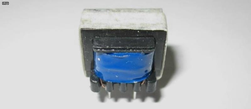
Figure 4 - 1k:8Ω Transformer
If you use a transformer, using the high impedance output from the drive circuit isn't strictly necessary, but it's far better to keep it in place and it works more effectively. This lets you change to an 8 ohm tank without having to change anything else. It's just a matter of removing the transformer, and connecting the 8Ω tank directly. The transformers are usually readily available from hobbyist suppliers, or you can get them from eBay. Prices are highly variable, so you need to search carefully. Expect to pay somewhere between AU$1.00 and AU$20.00 each. Some have a laminated steel core, and some have a ferrite core. Ferrite tends to saturate more abruptly than steel, and you might need to try a couple to find one that works properly. The transformer pictured above has a ferrite core, and during tests it worked just fine - better than I expected.
Figure 5 - 1k:8Ω Transformer Drive Circuit
When a transformer is used, it doesn't matter if the input coil is grounded or not, but a floating input ensures that you'll get the minimum crosstalk between the 'dry' and 'wet' signals. The circuit above shows how it's connected. The drive amplifier is the same as that shown in Figure 2, but the gain is set to provide an output of about 40mA/V. Based on the tests I've done, this is the maximum you should use, and you will need to run your own tests to ensure that saturation isn't a problem over the required frequency range. Note that the transformer is wired 'backwards' with the 8 ohm winding used as the primary.
While my tests show a transformer output (into 1kΩ) of only about 1V at 100Hz before saturation, this is sufficient to drive the high impedance coil. Transformers always saturate more easily under no-load conditions, and the reverb drive coil has a rising impedance with frequency. Therefore, as the frequency increases, so does the impedance, and the transformer should not saturate at the lowest or highest frequencies of interest (about 100Hz and 6kHz respectively). I verified this, and was ale to get well over 20V RMS output at 6kHz. The maximum coil current at 100Hz is about 50mA before saturation becomes evident on the scope, but even quite severe saturation is not audible in the reverb output. Use the suggested values for R4, C4 and R9 shown in Table 1. Increasing the drive current to any more than 40mA/V to the 8Ω primary will cause transformer saturation. The minimum suggested value for R4 is 22 ohms.
You could also use a salvaged transformer from an old transistor radio if you have one available. Many have a centre-tapped primary (which is used as the secondary in this role), so you can choose the ratio that works the best. These transformers have low inductance, and if you need unusually good bass response you may need something better. The core is small and easily saturated, but if you choose wisely it should still be more than sufficient for reverb drive.
Note that the PCB (when available) does not have provision for the transformer on-board, as that would limit the footprint and you may not be able to get a transformer that fits.
This project has been a long time coming, and I apologise for the rather long delay between initial publication and finally having a complete system available. I hope it's been worth the wait, as I'm quite pleased with the facilities that this version offers. The final piece fell into place as this article was being written - the compressor. Much of the time, the circuit will be used at levels below the compressor threshold, but if it's driven hard, the reverb 'tone' should remain intact, without the noises that can be generated if a drive coil is pushed beyond its limits.
Unlike previous circuits, this is a single, complete reverb sub-system. The PCB will be available eventually (I have no expectations at present - Coronavirus/ COVID-19 has impact everything), and everything is on one board. The pots (for drive level and reverb output) can be 10mm PCB mount types or can be off-board if preferred. The circuit needs a ±15V supply, with the peak supply current being no more than 150mA with the recommended opamps, and depending on the drive current you set it up for.
The limiter is optional, but is an excellent safeguard against severe overdrive. It also provides some interesting 'effects', especially with deliberate overdrive. Since the input, output and compression levels are all adjustable, you can set it up to provide exactly the sound you want. The PCB provides for reverb and drive level, and the 'dry' signal can be enabled or disabled. If the unit is used as an external reverb (outboard from a mixer for example) the dry signal isn't required, but if used in a guitar amp effects loop, the dry signal is needed so you get the guitar sound as well as reverb.
Because it uses a 'proper' mixer (U2A), the circuit cannot oscillate even with maximum reverb, as there is no feedback path. This means you can obtain far more reverb than most guitar amps can provide. This isn't needed often, but it does provide options that are otherwise unavailable. You can build the circuit without the limiter, which can be added later if you decide it will be useful.
Because I don't have PCBs at the time of writing, there may be a few (hopefully minor) changes to the circuits when the prototype is built. The basic principles won't change, and variations are more likely to be component value changes where necessary. The information here will be updated as soon as I can complete a PCB prototype.
If you don't want to wait for the complete PCB, see Project 211 which uses a P113 headphone amp board, and is perfect for the drive and recovery stages. The required gain and mixing stages can be added using the P94 'Universal' Preamp/ Mixer'. This also can provide tone controls that may be found useful. The compressor/ limiter (if required) can be made easily on Veroboard.
Almost all the reverb tanks that you will see are Accutronics (Now Called Accu-Bell Sound Inc. - Accutronics & Belton).
Note: This is not a specific endorsement of their products or services, but a reader service. Unfortunately, someone decided it was a good idea to run the entire site in 'Flash' (it's not!).
 Main Index
Projects Index
Main Index
Projects Index