
|
|
| Elliott Sound Products | Spring Reverb Units |
 Main Index
Articles Index Main Index
Articles Index
|
Reverb is one of those effects that simply will not go away. While there are some excellent DSP (digital signal processor) based reverb systems that sound very natural, the unique sound of spring reverb tanks is still preferred by a great many guitarists and many electric/ electronic organ players as well. It becomes obvious that the sound of a spring reverb must be a classic when it becomes available as a software plug-in for computer based recording systems.
For detailed info on the history of reverb, the first stop will often be the Accutronics website. There is also a lot of information provided showing various drive methods, a simple recovery amplifier, overload characteristics, and much more.
The problem for the hobbyist or DIY builder is that some of the information is too detailed and the circuits are too generalised. This makes component selection difficult, and makes it almost impossible for the average enthusiast to work out what is needed for their application. While it's nice to have so many choices (they make a lot of different tanks), it's extremely difficult to work out the combination of the most suitable tank, optimum drive circuit, and the ideal recovery amplifier.
With this in mind, and given that I have a reverb design amongst the projects, there is actually nothing specified as to the best tank to use to ensure good performance. I have an old 4FB2A1A tank that was used for some of the tests described. This tank is a Type 4, and has drive coil impedance of 1,475 ohms (~1.5k), pickup coil impedance of 2,250 ohms (2.2k) and is designed for medium reverb time (1.75 to 3.0 seconds). All this information is available from the Accutronics website and can also be seen below.
Something you don't see every day is a video of reverb coils in action. The video was captured by a reader who let me know about it. Taken with a high-speed video recorder and replayed in 'slow motion', you can see the way the transducers work.
It should be mentioned that the info provided is often at variance with reality. A measurement of inductance (for example) gives a very different value from that calculated, but an impedance scan shows that the quoted figures are fairly close. Inductance measurements on transducers often give incorrect results, because the coil resistance is high enough to trick the meter into claiming the inductance is much higher than it really is. Back-EMF created by the spring 're-energising' the magnetic bead doesn't help either.
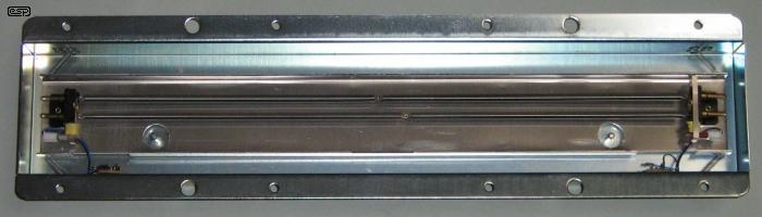
Figure 1 - Accutronics Reverb Tank
Figure 1 shows a complete spring reverb tank. I was originally going to show a photo of one I already have, but it looked a bit too gruesome, so I got a new one to do some further experiments with. While the old one has seen better days (I think it's at least over 30 years old) it still works perfectly. The single biggest problem with it is that the input coil has a very high impedance, making it rather difficult to drive. The new tank is a 4AB3C1B - 8 ohms input, 2,250 ohms output, long delay. For all tank info, see Part Numbering Details, below.
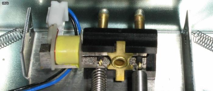
Figure 2 - Drive Transducer Details
Above, you can see a close-up of the drive coil. All coils are colour coded to show their impedance. This info was not included in the Table 1, but it is included in Table 4 at the end of this article. It is also available from the Accutronics website. This can be helpful if the model number is missing or can't be read.
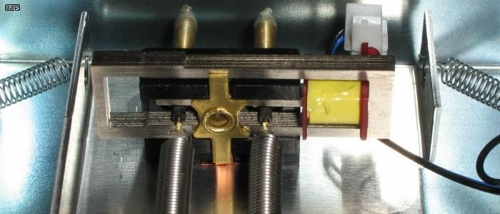
Figure 3 - Pickup Transducer Detail
Here's a close-up of the pickup coil. The basic design of these tanks dates from around 1960, and has changed very little in all the time since then. As a result, it is possible to replace even extremely old tanks if necessary, and a direct replacement is almost always available. The transducers of this tank are virtually identical to those in my 30-odd year old tank.
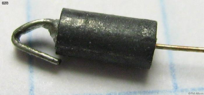
Figure 3a - Pickup Transducer Magnet
Here is a picture that you won't see very often. This is a photo of one of the transducer magnets, taken from a broken reverb spring. To get an idea of the size, the magnet is sitting on a piece of 5mm grid graph paper. You can see the ends of identical magnets in the two photos above of the drive and pickup transducers, but it's hard to gauge the size from those other photos. These magnets have a rotary movement within the magnetic field of the pole pieces, and the signal is passed down the spring as a torsional (rotary) wave. However, the magnets do not 'spin', they move with a (roughly) circular motion.
Figure 4 - Accutronics Reverb Tank Drive Coil Impedance
The above impedance scan was taken of an Accutronics 4FB2A1A reverb tank (my old one). I used a woofer tester normally used for measuring the Thiele-Small parameters of loudspeakers to do the impedance graph. The impedance was also verified using a vector impedance meter which gave virtually identical results. The spikes at the high end of the sweep are caused by the measurement signal causing a disturbance in the springs and confusing the reading. Although the impedance is different from the claimed or calculated value at various frequencies, the difference is inconsequential. In theory, the impedance at 6kHz should be around 8.8k, but is closer to 6.5k - while this might seem like a large error, it makes little or no difference to the way the tank behaves.
Note that in the circuits shown below, I have used standard polarised electrolytic capacitors, including in locations where there is no polarising voltage. This is (perhaps surprisingly) perfectly alright provided the voltage (AC or DC) never exceeds about 1V. In all cases where polarised electros are shown the actual voltage will be less than 100mV. The exception is Figure 6, because the voltage across C4 may exceed the 1V threshold because it's a discrete design. An addition to the original circuits is C3 in Figures 5, 7 and 14. This cap allows more signal level before clipping, but it is optional. If it's not used, you are unlikely to run out of drive with Figure 5, but I recommend that it be used in the Figure 7 and Figure 14 circuits.
It is important that all opamps are bypassed with a 100nF cap between the supply rails, and/or from each supply rail to ground. These are not shown on any of the drawings! The cap(s) need to be located as close as possible to the IC to prevent oscillation. If an NE5532 oscillates it's not always visible at the outputs, but distortion is increased dramatically. Needless to say this applies to all the circuits shown. Bypass caps should be 100nF 50V multi-layer ceramic (aka 'monolithic') types. Two 10µF electrolytic caps should be used at the power supply inputs to ground, one from the positive supply and one from the negative. Larger caps can be used if preferred.
The drive circuit for any spring reverb tank is critical - by far one of the most critical part of the final system. The drive coil has a nominal impedance specified at 1kHz, but it also has considerable inductance. It is actually quite difficult to drive properly. It is necessary to know the optimum drive level, but this is specified as a current, not a voltage. While many commercial amplifiers just use an ordinary opamp to drive the input coil, this seriously limits the available drive current. Most opamps can supply no more than ±10mA (peak), with many not even able to achieve that. For an 8Ω drive coil, anything that cannot provide at least ±100mA is going to cause problems.
In order to produce a constant drive level into a coil as the frequency varies, it is necessary to drive the coil with an amplifier that produces constant current, rather than the much more familiar constant voltage. This can be done with equalisation, but it is preferable to use a dedicated amplifier with a high output impedance. This approach is easier, and it automatically adapts itself to the actual (as opposed to nominal) value of impedance at any frequency of interest. However, current drive may accentuate the upper frequencies, and in some cases this might be considered excessive. You also need to consider the fundamental frequencies and harmonic produced by a guitar, as the level falls off above 1kHz, so you may not need quite as much drive voltage as initial calculation may imply.
It is common to include a high pass filter as well, because the spring reverb effect doesn't work well at low frequencies. While it is possible to get good low frequency performance, it's generally undesirable because it tends to muddy the sound too much. Accutronics provides a table of impedance and RMS drive current at 1kHz, but some of the information that one really needs is missing. To rectify that, I have added a column giving the approximate inductance and deleted the columns that are unimportant. The following table applies to the Type 4 tank - the 425mm long, 4-spring version as used by Fender and many others.
It's worth noting that some of the info on the Accutronics site is either misleading, contradictory or just plain wrong. For example, they state that the drive coil should be driven to near saturation, say that the saturation level is 2.5A/T (ampere turns), then show a graph with the nominal level shown as 3.5A/T. Although no explanation is given, that indicates a level 3dB more than the 'recommended' value.
| Type 4 Input | Coil Impedance | DC Resistance | RMS Current | Peak Current ¹ | Inductance |
| A | 8 | 0.81 | 28mA | 80mA | 1.27mH |
| B | 150 | 26 | 6.5mA | 19mA | 24mH |
| C | 200 | 27 | 5.8mA | 17mA | 32mH |
| D | 250 | 36 | 5.0mA | 15mA | 39mH |
| E | 600 | 58 | 3.1mA | 9mA | 95mH |
| F | 1,475 | 200 | 2.0mA | 6mA | 234mH |
There are several different tank styles available, most of which are somewhat smaller than the Type 4. Being smaller, this means fewer (or shorter) springs, and different reverb characteristics. The Type 4 has been the unit of choice for many guitarists for a very long time, although some do prefer the other types. The details in this article are equally applicable to any reverb tank, but some small changes may be needed to account for different impedances.
The first thing that the intending user should look at is the 1kHz impedance. For example, a coil with an impedance of 1,475 ohms at 1kHz requires a voltage of 2.95V RMS to produce 2mA coil current. At 10kHz, this rises to 29.5V because the coil impedance rises to 14.75k. While this voltage and current are certainly achievable, the drive amp ideally needs a supply voltage of over ±40V - often, this is simply not available. It is possible to use a cheap transformer though - see Transformer Drive below. The voltage at a more sensible frequency (say 5kHz) is still far more than can be obtained from an opamp, and will be around 20V RMS.
For use with an opamp or small IC power amplifiers, we must use a lower supply voltage, and with these the high impedance drive coil is of no use. All in all, the 8 ohm coil is the most attractive, although current is higher than we might like at 28mA RMS (about ±40mA peak). The optimum impedance for opamp drive is 150 ohms ('B' input coil), and even at 10kHz when the impedance has risen to 1500 ohms, the voltage remains below 10V RMS. With a peak current of 9mA, an opamp will require a couple of small transistors to boost the output current, and we end up with a circuit such as that shown in Figure 5. For opamp drive, the 150 ohm coil doesn't allow much headroom though - it would be nice if there were an intermediate impedance available. Something around 50 ohms would be perfect.
An 8 ohm coil is a good choice if the power supply is adequate, and a boosted opamp (or - with many caveats - a chip amp such as an LM1875) will be needed to drive the coil. The maximum voltage needed is 2.24V RMS (at 10kHz) to be able to provide the full 28mA needed for maximum output. While the chip amp seems like a good choice and is superficially easy to use, the cost is considerably higher than a boosted opamp. Current drive is harder too, because most IC power amplifiers are not stable at unity (or low) gain. This demands additional complexity to achieve unconditional stability. If a chip amp is used it's generally easier to use a resistor in series with the tank drive coil, but that's not without its problems. The following circuit will drive 8 to 250 ohm coils well, without any major changes.
Figure 5 - Basic Drive Circuit For Low Impedance Coil
The circuit shown above requires that the input coil be isolated from the reverb tank chassis. The Accutronics website shows a current drive arrangement that doesn't require an isolated input coil, but I recommend that you stay well clear of it because it's wrong. The circuit is meant to be based on a 'Howland current pump', and while these can be made to work very well, the results may be unpredictable if you don't know how to set it up properly. The Accutronics circuit shown as 'drive4.pdf' has several serious mistakes, and will not work at all ! Pretty much everything about the circuit is wrong, which is more than a little disappointing (and as of November 2019, it still hasn't been fixed!). While the 'drive5.pdf' circuit is basically functional, it's an extraordinary example of poor design, as the high frequency response as shown is woeful (even into a resistor!). I recommend that all Accutronics drive circuits be avoided.
The input voltage required for full drive from Figure 5 is determined by the coil impedance and the value of R2, and with a 150 ohm coil and R2 set to 150 ohms as shown provides 6.5mA/Volt. Note that the value of R2 and R7 must be selected based on the coil impedance. The following table gives the suggested values for these resistors, based on the coil impedance. Some experimentation may be needed, but only the values of R2 and R7 need to be altered to affect the gain and proper drive characteristics.
| Coil Z | R2 | C2 | R7 | Current | Volts @ 6kHz | mA/ V (1kHz) |
| 8 ohms ¹ | 33 ohms | 47µF | 150 ohms | 28mA RMS | 1.34 V RMS | 30mA/V |
| 150 ohms | 150 ohms | 10µF | 3.3 k | 6.5mA RMS | 5.85 V RMS | 6.6mA/V |
| 200 ohms | 180 ohms | 10µF | 3.9 k | 5.8mA RMS | 6.96 V RMS | 5.6mA/V |
| 250 ohms | 220 ohms | 10µF | 5.6 k | 5.0mA RMS | 7.50 V RMS | 4.5Ma/V |
| 600 ohms ² | 330 ohms | 10µF | 12 k | 3.1mA RMS | 11.2 V RMS | 3.0mA/V |
| 1,475 ohms ³ | n/a | n/a | n/a | 2.0mA RMS | 17.7 V RMS | n/a |
Notes: 1 When driving an 8 ohm reverb coil, R3 and R4 may need to be reduced in value (3.9k is suggested) or the output transistors may run out of base current causing the circuit to clip prematurely. 2 The Figure 5 circuit is marginal with the 600 ohm coil, as it is unable to provide more than about 7V RMS, so high frequencies may cause clipping. It's unlikely that you'll ever hear the distortion though. 3 Again, the Figure 5 circuit is not suitable for the 1,475 ohm coil, as it can't provide a high enough voltage to get good results. The circuit will run out of drive voltage at about 3kHz, and a high voltage drive circuit such as those shown in Figures 6 or 7 is needed.
While it might seem perfectly alright to use an opamp to drive coils that need less than 10mA, it's more likely than not that it will be disappointing. Most opamps can provide up to ±20mA (peak), but that is usually a measure of the short circuit current. Attempting to get a useable signal level at the maximum current may get (just) enough level, but allows no headroom. In some cases you can use two opamps in parallel (with 'current sharing' resistors at the outputs), but even that can be marginal. The small extra effort to make a boosted opamp circuit such as that shown in Figure 5 is usually well worth it. However, if you use both halves of an NE5532 opamp in parallel, that combination can drive coils from 150 to 250 ohms fairly easily, and will generally be acceptable. Use a 10 to 22 ohm resistor at the output pin of each opamp (pins 1 and 7), and U1B will copy the output of U1A and sum the current from each opamp.
Figure 5A - Dual Opamp Drive Circuit For 150-250 Ohm Coils
The above drawing shows how it's done. With the NE5532 opamp, the circuit can drive a 300 ohm load easily, and is an economical alternative to the Figure 5 circuit, both in cost and PCB real estate. The values for R2, R7 and C2 are the same as shown in the above table, selected for the drive coil impedance. This circuit is not suitable for 8 ohm tanks, but you may just get away with it if you are willing to sacrifice some output level.
After getting a new 8 ohm tank for some experiments and to take a few measurements, it turns out that the coil can be driven somewhat harder than claimed. I was able to drive the 8 ohm coil to 250mA at 1kHz before saturation (almost 10 times the current claimed). The saturation current remains roughly the same at all frequencies from around 300Hz and up, and at 1kHz the voltage was measured at 2V RMS. This rises to 8V RMS at 5.8kHz, the highest frequency where useful output was measured. I drove the input transducer from an LM1875 amplifier, feeding the coil via a 10 ohm resistor. Amp output at 5.8kHz is a little over 8V RMS, and it was the resistor alone that reduced the drive voltage at lower frequencies. However, I don't recommend that you drive the coil to the maximum, because it may shorten the life of the unit. Somewhat surprisingly, using almost 10 times the rated coil current does not produce almost 10 times the output level - you will be lucky to get even twice the output. On that basis, using a much higher drive current should not be attempted (other than for experiments of course).
The Figure 5 circuit is capable of driving an 8 ohm coil to several times the maximum rated current at any frequency. The values shown above will all provide slightly more than the manufacturer suggested transducer drive current with an input voltage of about 1.5V RMS. A voltage to current converter is defined by its transconductance which is shown in Table 2 (above) in mA/V. For example, if the circuit provides 5mA/V, you get an RMS current of 5mA with 1V RMS input, or 10mA with an input of 2V.
Be aware that if the coil is heavily overdriven you'll get some distortion, and too much overdrive can damage the coil due to overheating if the available voltage and current is excessive. This is actually fairly unlikely - even with 250mA in the 8 ohm coil the dissipation is negligible, but there is a very real risk of mechanical damage. It is best to avoid clipping the drive amplifier, so some headroom is needed. Amp clipping may be worse than core saturation, and the level needs to be monitored for best results. In general, it seems to be ok to drive the coils with up to double the rated current, but I wouldn't go beyond that.
The circuit of Figure 5 is not suitable for the higher impedance coils - 600 ohms is marginal, 1.465k is not at all suitable. Fortunately, the signal level above 2kHz or so drops off at ~6dB/ octave, so maximum drive voltage is never needed at 6kHz. See below for more on that topic. R2 sets the sensitivity, and can be determined as ...
R2 = VIN / ICOIL
For example, for an 8 ohm coil and 28mA input from 1V, R2 becomes 1 / 0.028 = 35 ohms.
A 33 ohm resistor is fine in this case. R7 is based on an estimation, where the resistor value is roughly 20 times the coil's 1kHz impedance. Reduce the value of R7 for less treble response and vice versa. With R7 set at 20 times the coil impedance, high frequency response is 3dB down at about 5.5kHz. The resistor sets the amplifier's output impedance, so it can't keep rising with increasing frequency. The effect is identical to using a voltage amp with a series resistance. The choice of C2 is somewhat personal, and it should ideally be a bipolar electrolytic type as indicated. The values shown will give a fairly good drive level down to about 100Hz with all coil impedances, and if less bass response is desired it's better to reduce the value of C1. As shown the -3dB frequency is 159Hz. A smaller value will give more aggressive bass rolloff and vice versa.
We also need to consider the maximum voltage needed to provide the required current into the coil at high frequencies. At 10kHz, we need more voltage than the maximum possible from an opamp. Fortunately, response to 10kHz is not only unnecessary but is also undesirable, and it won't be reproduced by the tank anyway. An upper limit of ~6kHz is usually more than enough, so there is some headroom, although it is marginal with the 600 ohm coil (I suggest that you use the high voltage circuit for that if you want the maximum headroom).
For an 8 ohm coil, R2 needs to be 33 ohms for a 1V RMS input voltage. The dissipation of Q1 and Q2 is about 160mW at full level and 1kHz, and remains relatively constant with frequency. Peak dissipation is below 500mW - well within the ratings of the BC639/640. Feel free to use BD139/140 if you prefer. They will run cooler because they are considerably larger than the TO92 devices. The power supply demands are naturally noticeably higher than would be the case with a higher impedance coil, but are still easily handled by P05 or similar.
As the drive coil impedance rises further, the voltage needed to drive the coil exceeds that available from any common (cheap) opamp. The current is low, but this doesn't help a great deal if there is no easy way to get the voltage needed. The 1,475 ohm coil requires a voltage of just under 15V RMS at 5kHz, and almost 30V RMS at 10kHz. Allowing for a maximum sensible frequency of 7kHz, you'll need 21V RMS to drive it. This can be obtained easily enough using the ±35V supply for a typical 100W solid-state guitar amp (such as Project 27). The drive circuit must be discrete though, because no common opamps are rated for such a high voltage. While a pair of opamps in bridge would work, obtaining stable current drive in this configuration is not easy. Even in that configuration, the maximum voltage available without distortion is ~20V RMS - not enough for the high impedance coil, especially since some headroom is desirable.
Figure 6 - Basic Discrete Drive Circuit For High Impedance Coil
The discrete amplifier is not designed for outstanding performance because it's just not needed. It will drive the high impedance Accutronics coil to the full 2mA RMS required though, and the circuit as shown should satisfy anyone who has a high impedance tank. Since I'm one of those (since I have my old high-Z tank as well as the new one), I built the circuit to verify that the simulation is correct and because I want to be able to use the tank I have. It works as described, and is certainly not a difficult or expensive circuit to construct. I do suggest that the power supply rails are decoupled with a resistor and a capacitor as shown. C5 and C6 can be made larger if you prefer.
VR1 is an adjustment to enable the output voltage to be adjusted to zero. This is important to ensure maximum headroom. C4 (10µF bipolar electrolytic) is included to ensure that no DC flows in the drive coil. DC causes the magnetic circuit to saturate, and this reduces sensitivity and greatly increases distortion. It is also important that the circuit is driven from a low impedance. In the interests of simplicity there is no additional decoupling in the network of R1, R3, D3 and VR1, so a high impedance source may allow some hum and noise from the power supply to enter the amp's input. A low impedance source lets C1 act as a coupling cap and also decouples any noise. C1 is chosen to provide the desired low frequency response. With 100nF as shown, the -3dB frequency is about 72Hz. Reduce the value of C1 to reduce the amount of bass and vice versa - this is often a very personal choice.
This simple circuit has a deliberately limited output impedance, and the constant current characteristic only extends to about 6.5kHz. The circuit has the equivalent of using a resistance in parallel with the coil as shown in Figure 4 - all drive circuits require a high frequency limit. In this case, R5 (22k) is effectively in parallel with the coil, although it may not look like it at first glance. The response of any spring reverb tank is very limited above ~5kHz anyway, and there is little point trying to get very high frequencies. Even if the tank could provide good HF response, it would sound unnatural because natural reverb at high frequencies is very uncommon. Despite the high operating voltage, this circuit will still struggle if you drive it a bit harder than normal. With 2V input at 5kHz, the amp will clip - this is unlikely to be a problem though, since the energy at this frequency is usually much less than at lower frequencies.

Figure 6A - Simplified Discrete Drive Circuit For High Impedance Coil
The circuit shown above is a simplification, but with the high supply voltage it will never run into problems due to the DC offset. Rather than messing around with a zener and pot, we just accept that it has around -2.5V DC offset, so a polarised cap can be used for C4. C1 can be increased for better low-frequency performance (this applies to Fig. 6 as well).
All of the tanks can be driven from a voltage amplifier with a series resistance or an equalisation (treble boost) circuit. The value for the series resistor needs to be the same as R7 listed in Table 2 to get the same performance, and it becomes apparent quite quickly that the voltage needed can be quite high. For example, if we assume a 150 ohm coil with a 3.3k series resistor, you need over 20V RMS to get the rated current at all frequencies of interest. The only tank coil that can be successfully driven from a voltage amplifier is the 8 ohm version with a 150 ohm series resistor. This only needs about 5V RMS, and that's easy to achieve with a chip amp or boosted opamp.
All other coil impedances need a lot more voltage, in general far more than it is reasonable to achieve. The 600 ohm coil needs over 35V RMS via a 12k resistor, and that's more than you get from an amp running ±35V supplies. The alternative is to include a filter before the amp that provides a 6dB/ octave boost from ~70Hz or so, then the coil can be driven directly from the amp's output. A suitable filter would be a 10nF capacitor feeding a 2.2k load, and that will provide a voltage increase of 6dB/ octave up to ~5kHz.
Again, equalised voltage drive is best suited to low impedance coils and can work well, but it's hard to recommend any form of voltage drive as being appropriate for a number of reasons. A major drawback is that the low resistance coil is connected directly to an amplifier, so even a tiny DC offset may cause partial drive transducer saturation. While you can use an isolating capacitor, it needs to be fairly large (at least 470µF for an 8 ohm coil) and there is no net benefit.
A simple way to use voltage drive (with equalisation) is a bridged amplifier, for example using two Figure 5 amplifiers. One is driven with inverted phase (180°) in the same way as a bridge tied load (BTL) power amp for speakers. You can get the necessary voltage swing easily, and the reverb tank must use an isolated input connector. It will certainly work, but the output capacitor is still necessary unless you are willing to add a DC offset control. It's hard to recommend this approach because the drive amp is twice as complex, and as already noted using a voltage amp with EQ or series resistor is not ideal.
So, while voltage drive (single ended or BTL) with an equaliser can be used, it's really not recommended and no circuits will be shown.
Another way you can drive a high input impedance reverb tank is to use a transformer. Small transformers may be rated for about 350mW or so, and are fairly cheap (around AU$5.00 each for the one I used for testing). The core is small and will saturate quite easily, but even if the transformer core does saturate you won't hear it. The springs don't have the fidelity to reproduce anything cleanly. The transformer is used in reverse, so the 'primary' is used to drive the reverb tank and the 'secondary' is used as the primary. Transformers work happily either way, and there is no reason not to use them backwards.
There is one thing that you will have to do if you go this way ... experiment. Because transformers will vary and the coupling between the transformer and drive transducer is something of an unknown quantity, you have to be prepared to try different variations of the circuit until you get a good result. Unlike direct drive using a current amplifier, using a transformer may create unpredictable response. The arrangement shown below has been tested and it works as described. Input level will normally be around 1.5V RMS.
Figure 7 - Transformer Drive Circuit For High Impedance Coil
Very small transformers are available from various suppliers, and the one suggested has a primary of 1k ohm centre-tapped, and a secondary rated for 8 ohms. Because transformers have no intrinsic impedance of their own, this can be used in reverse using the circuit shown in Figure 7. The amplifier drives the secondary, and the 'primary' is used for the output. This will work whether the input coil on the reverb tank is isolated or not - it makes no difference either way. However, you do need to be mindful of earth (ground) loops which may cause instability.
The impedance ratio as noted above is 1k:8 ohms, so the turns ratio is the square root of the impedance ratio ...
ZR = 1k / 8 = 125:1
TR = √125 = 11:1
Therefore, if we supply 1V to the 8 ohm winding, we should get around 11V across the full secondary (ignoring the centre-tap). If the reverb drive coil has an impedance of 1k, the drive amplifier will 'see' an 8 ohm load. As seen from Figure 4, the actual reverb drive coil impedance varies over a wide range, but that will not cause stress to the driver circuit shown in Figure 7. Getting 17V RMS at 6kHz is easy, and only needs an input voltage of a little over 1.5V from the driver amplifier.
The circuit shown is almost the same as Figure 5, and the circuit is operated in voltage mode rather than high-impedance current mode. The gain is two (set by R2 and R7), and the voltage to current conversion is done by R8 and the transformer itself.
If you wanted to drive a 600 ohm coil with one of these transformers, you could simply use half the primary winding (as the secondary of course). Using half of the winding doesn't mean the impedance is (nominally) 500 ohms - it actually ends up being only 250 ohms, ¼ of the impedance of the full winding. This is ideal for driving 200 or 600 ohm input coils on the reverb tank. With a 600 ohm drive coil, the transformer's nominal impedance at 1kHz will be about 20 ohms in theory, but the way the transformer is made might cause that to be somewhat different (these are hardly precision components). I did try using the 8:250 ohm alternative with the high impedance coil and while it works, you'd need to be very careful to avoid transformer saturation because it's marginal at best. No problems at all with a 600 ohm reverb drive coil though.

Figure 8 - Close-Up Of A typical Miniature Transformer
These transformers were originally designed for use as output transformers in transistor radios and similar (very) low output amplifiers. The early versions used a laminated iron core, but those you get now often use ferrite. A few details about the transformer are in order. Predictably there is almost nothing in the info from any seller other than the impedance ratio and power handling (350mW). The primary resistance is 330 ohms (end-to-end, ignoring the centre tap), and the secondary resistance is about 3.25 ohms. Primary inductance measured 1.7H and secondary inductance is about 7mH. The core measures 14.5 x 11.5 x 6.5mm and the whole thing weighs all of 6 grams. Although the one shown in the photo was obtained in Australia, similar transformers appear to be available from many sources worldwide.
It doesn't matter if the one you can get is larger or has a different impedance ratio, as long as it's within 50% or so of the unit I used. I wouldn't entertain anything smaller than the one I tried because it will saturate too easily. In reality, you can get by with a tranny that provides a step-up of anywhere between 3 and 12 times, so something rated for (say) 2,500:50 ohms (~7:1 turns ratio) is just as easily used and may even work better than the one I have. You might need to adjust the gain of the drive amplifier slightly, but everything else will be unchanged. You will need to test the circuit to ensure there's no transformer saturation at all frequencies and levels of interest.
From the tests I performed, the transformer will almost certainly saturate well before the reverb drive coil. I leave it to the constructor to determine whether this is a problem or not. It's also possible to use a small mains transformer, which will have lower losses and be much harder to saturate at the current levels needed. A 230V to 12-0-12V (24V CT) is ideal, and the full 24V secondary is used as the primary, with the secondary driving the reverb tank. If your mains is 120V, you'll need a single 9-12V winding to get a useable step-up ratio. If you choose to use any transformer to drive the coil, you will need to experiment to find the optimum drive parameters.
I'd like to thank 'PhAbb' for suggesting the use of one of the el-cheapo 1k:8 ohm transformers to drive high impedance coils. (He knows who he is, and that's the main thing.)
Recovering the signal is every bit as important as driving the coil properly. The recovery circuit that's shown in the 'drive1' PDF at Accutronics is barely adequate, and will be rather noisy. It is important that the opamp used gives its best performance with low to moderate source impedances, and maintaining a high load impedance is essential for optimising the signal level. Both high and low frequency response should be tailored to suit the expected response of the tank itself. I would suggest that a range from 200Hz to about 6kHz is about right. Output above 7kHz is almost nil, so a wide bandwidth pickup amplifier is not needed. The relatively low bandwidth maximises signal to noise ratio - essential since the output level is generally well below 10mV even at maximum drive level.
| Type 4 | Impedance | DC Resistance | Inductance * | VOUT (RMS, Typ) |
| A | 500 | 42 | 65mH | 3.0mV |
| B | 2,250 | 200 | 270mH | 6.5mV |
| C | 12,000 | 800 | 1.7H | 15mV |
The table shows the impedance, DC resistance, approximate inductance and claimed output level for the three output coils available. The inductance value was calculated, based on the claimed impedance at 1kHz, so it should not be taken as gospel. It does give a reasonable starting point though, and can be used to estimate the peaking frequency caused by C1. To calculate this for yourself, use the formula ...
f = 1 / ( 2π × √( L × C ))
Several opamps are well suited to the task, and of these the dual NE5532 (or NE5534 for a single version) is one of the better choices. These opamps have low noise and excellent drive capability for low impedance loads. Based on the datasheet values, they are best suited for a source impedance of 3kΩ or so, which is ideal for the type 'B' coil. The NE5532 has rather uninspiring DC offset figures, but that's not an issue in this application. You could also use the OPA2134 dual opamp - it's quiet, but (IMO) too expensive and overkill for a reverb circuit. With a typical output level of around 6mV (which is frequency dependent), a total recovery gain of about 150 (43dB) is needed to obtain a 1V output. Although this can be obtained from a single opamp, the result may not be satisfactory. An output level of around 500mV is usually sufficient for a 1V 'dry' signal. More than that means that the reverb is dominant, tending to 'drown out' the original signal (of course, you may want to be able to do that, so you can use more gain if necessary).
Accutronics recommend adding a capacitor in parallel with their 'B' (2.25k) coil, for 'improved high frequency response'. While this is a good idea, the Q of the tuned circuit may be found to be too high. If this proves to be a problem, adding a resistor in series with the capacitor tames this nicely, reducing the peak amplitude and spreading the HF boost over a wider range. This is included in the circuit below, but the resistor and/ or capacitor value will probably need to be tweaked to get the sound you want.
Figure 9 - Generalised Recovery Amplifier Circuit
The circuit shows the basis for the recovery amp. Gain is 40dB (x100), and may be reduced if necessary (not very likely). I do not recommend attempting more gain from a single stage. Vary the value of R1 to adjust the degree of high frequency peaking created by C1, and change C1 to raise or lower the frequency peak. With the values shown, the peak is about 3dB at 2kHz (relative to the 1kHz level). A smaller resistor increases the peak amplitude, and a smaller cap increases the frequency. 4.7nF gives a frequency of around 4.6kHz and increases the peak's amplitude to 9dB, still with the 2.2k resistor for R1. These components are interactive, and also depend on the inductance of the transducer. Accutronics suggest a 2.2nF capacitor directly in parallel with the pickup coil, but that's unlikely to be entirely satisfactory for most players. I don't think many people would be happy with a 33dB boost at 7kHz, as it will have little audible benefit.
R2 prevents the opamp from swinging to the supply rail if (when) the reverb tank is unplugged. It must be high enough to prevent the coil inductance from causing premature high frequency rolloff, and should be at least 10 times the nominal coil impedance (100k is shown, but anything from 22k to 220k will be alright). Gain will need to be increased (by adding another stage) for the 500 ohm coil and reduced for the 12k coil. The latter is probably a poor choice, and I suggest the 'B' coil if you have the opportunity for be choosy. It seems to be the most popular option so should be easy to get.
Gain is varied with R4 - lower values give less gain. A pot can be used at the output for level control. The NE5532 can drive low impedances easily, and the pot should be 10k (audio taper is preferred). The disadvantage of this arrangement is that all the gain is concentrated in the one opamp, and if the signal level is higher than expected (which reverb tanks can do fairly easily), there is a risk of clipping. However, for this to occur, the tank's output would have to exceed 80mV peak. I have tried, but was unable to get anywhere near that much. C6 is included to roll off the extreme top end, and that will help to reduce the apparent noise created by the high gain amplifier stage.
For maximum flexibility a two stage amplifier can be used with the level control between the two, but it's unlikely to be needed in reality, unless you have the 500 ohm coil and need additional gain. The second stage will typically only need a gain of 2-3, and this helps keep noise low. I've tested a recovery amplifier (using NE5532 opamps) with a total gain of up to 1,000 and was easily able to get an output level of 1.5V RMS - somewhat less than the specifications for the tank would imply. Noise was audible with no signal, but only when my workshop amp's gain was turned up so far that the result with signal would be deafening.
Reverb recovery amplifiers are fairly straightforward, but the impedance and sensitivity of the output transducer should be chosen based on response and noise. The 'B' output coil is probably the best of them, as it combines a reasonable impedance and output level, both of which are well suited to most low noise opamps. The high impedance coil does provide more level, but it's also more sensitive to load impedance and may suffer from high frequency attenuation. The low impedance coil doesn't have enough level, and may be more sensitive to radiated magnetic fields because of the extra gain required.
The final step is to decide if you want to add a clipping indicator or level meter to the drive amp. Having some form of metering allows the drive level to be set to the optimum, maximising output level. While generally not included in guitar amps because of the added complexity (and marginal usefulness), for a studio or PA application it's essential. Provided the drive amp has sufficient headroom, initially I recommended against any form of compression or limiting, and suggested that a meter or indicator is a relatively simple addition. Well, having tried it, I actually would recommend using a limiter (see below for the details).
The Project 60 LED level display is ideal. It's small enough to make it easy to fit into a small chassis, and is easily calibrated to indicate the maximum allowable drive level. The schematic (with values amended to provide about 1V RMS input sensitivity) is shown below. The meter is usually connected in parallel with the input to the drive amp, but there's no real reason that it can't be reconfigured to measure the signal level from the drive amplifier. See the project article for the required values of R3 and R4.
Figure 10 - LED Meter For Drive Level Monitoring
The meter should be operated in dot mode, because it is likely to be too irksome to provide the various different supplies needed to allow the unit to operated in bargraph mode, which increases the IC dissipation dramatically. The input sensitivity as shown is 1.25V with VR1 at maximum - this means that the sensitivity is pretty close to perfect for a nominal 1V input. LED current is set to about 11mA with R3 at 1.2k but it is easily reduced if needed - if R3 is increased to 1.5k the LED current is just under 9mA.
In many cases, a simple clipping indicator will be sufficient. It's actually harder to do than the LED meter though, because there are no PCBs available for a suitable circuit. If you don't mind some Veroboard wiring, you can use the circuit below.
Figure 11 - Clipping Indicator For Drive Level Monitoring
It's a pretty simple circuit and will work well with the suggested opamp, which is cheap but has limited performance. That's not a problem for this circuit. The second stage is a comparator, and is used to 'stretch' the overload peak so the LED is on for long enough for you to see. While the circuit might seem like overkill, really simple circuits just don't work well enough to be useful. It's important that the meter doesn't load the input or drive signal - depending on where you choose to connect the indicator - so a high input impedance is essential. The 100k pot is used to set the circuit gain so that a signal that just exceeds the coil current will trigger the LED.
If connected to the high impedance coil driver's output, the signal level applied to the circuit must be reduced because it's too high for the opamp. Input impedance needs to be as high as possible, and if used with the high impedance drive circuit, replace VR1 with a 1Meg pot. You may use as many of these circuits as you need, but most constructors will just use one for the drive amp.
In most cases, reverb units are designed to allow a 'dry' signal (no reverb), and use a pot to adjust the reverb level to the output. Sometimes (for example if used with a PA mixer), only the 'wet' signal (reverb only) is needed. To be really useful, the support circuitry should allow both modes of operation. Some guitarists might like to experiment with using a second small amp and speaker just for the reverb - it's an interesting sound.
The input stage can be balanced if desired, and likewise the output(s), although I've only shown an unbalanced version. It's useful to provide a high input impedance, but unless you plan to plug the guitar straight into the reverb circuit (not really recommended), there's not much point in having an input impedance above 22k or so. The 'Drive' control will typically be a preset, but if a limiter (such as that shown below) is used the pot isn't needed at all.

Figure 12 - Unbalanced Input, Mixer & Output Stages
The direct (dry) path has unity gain, so 1V input gives 1V output with the level control at maximum. The reverb input signal can be continued to a separate output if desired. If that's done, the wet (Reverb Out) output will have a level that depends entirely on the reverb recovery amp's gain, as it may be fed to another amplifier or mixer. The mix of dry and wet signals is set by the Reverb control - it's not really possible to give a gain figure, because it will vary widely, depending on the input source, selected reverb tank, etc. With the circuit shown in Figure 12, the gain is unity with the 'Reverb' pot at maximum.
While there are many more possibilities, the purpose of this article is to give ideas, rather than complete details of a defined project. Using ESP boards, there is a wide range of additional possibilities. Using a P94 'universal' preamp/mixer allows the addition of tone controls, as well as full mixing capabilities. The P113 headphone amplifier is ideal as a driver for low impedance tanks (8 ohms is no problem), and the second channel can be configured as the recovery amplifier. The only things missing are the simple clipping indicator and discrete high impedance drive circuit.
Rather than all the tedious messing around with level meters or clipping detectors, you might simply want to include a limiter before the drive stage. This ensures that the maximum drive level can't be exceeded, preventing the drive amp from clipping or the reverb tank drive coil from saturation. Yes, of course it's overkill, but the added cost is actually quite small. This limiter is almost perfectly matched to the driver circuits shown above, and the output level trimpot (VR2) will normally be set to about halfway. This is quite possibly the single most worthwhile addition to a reverb circuit, as it's really easy to get the perfect level and it will be very consistent.
Figure 13 - Compressor/ Limiter For Drive Amplifier
This circuit was developed for a project, and is one of the simplest I've ever seen. Despite that, it works very well, but the choice of opamp is limited because it must have a high drive capability. The NE5532 is perfectly suited to this, and that's what I used during the project development. In use, the level control (VR2) will be preset to give the maximum drive to the tank, and the compression control VR1 will be varied as needed. Make sure that the circuit is driven to maximum compression before setting VR2. The panel indicator LED is optional, and if not used will reduce the output level to about 2V RMS.
Some drive amplifiers that you find elsewhere may need to have their gain reduced if the compressor is included, because they may already have a high output level (up to around 3V RMS). The input sensitivity of all the drive amps shown here is around 1.5V RMS, so they should not need any modification. The compressor is quite capable of driving a unity gain stage to the maximum level needed for a typical tank. I tested it with the Figure 7 circuit, driving my old high impedance tank. Performance was exactly as expected - it works very well indeed. For step-by-step details on how to make your own optocoupler, see Project 145.
With the values shown, the limiter will be at the limiting threshold when the 'Compression' pot is at maximum resistance and with an input voltage of around 150mV. When the 'Compression' pot is at the minimum setting, input sensitivity is around 1.5V RMS. Gain can be increased or reduced by changing the value of R4. A lower value gives a higher gain and vice versa. If the first stage has a gain higher than 4 (e.g. R4 is less than 820 ohms), use a 47µF or 100µF electro in series with R4 to keep DC offset low. Polarity is not important because the voltage will be well under 100mV.
Another 'compression' system was suggested by a reader, who says it was used by a British company called Grampian (which operated through the 1960s and ceased trading some time in the 1980s). Their reverb unit used mainly germanium transistors, but the clever part was the use of a lamp in series with the tank. This approach isn't new (well, it can't be if it was used in the 60s  ), and it's been used in many small studio monitor speakers to protect the tweeter (often a small compression driver with horn loading).
In the original Grampian reverb unit (Types 636 and the 666 which came along later), the tank drive was a simple transformer driven push-pull low-power amp with no feedback, and the lamp was in series with the tank, bypassed with a 2.2µF capacitor. I would expect the sound to be a bit on the rough side given the overly simplified design (especially with germanium transistors), but I've been told that it doesn't sound too bad at all. Circuitry has come a long way since then, and it's now easy to make a circuit that will outperform anything from that era. The lamp is still clever though, and I don't know of any other manufacturer who has used that approach. Having said that, it does appear that Hammond also used a lamp limiter, but I could find no details about how it was implemented.
Figure 14 - Lamp Based Compressor For 8 Ohm Tanks
In the schematic, you can see that R2 has been augmented by the lamp, wired in series. The amplifier is still set up for an 8 ohm tank, and uses current drive to the tank's drive coil, but the gain is determined by the resistance of the lamp and R2 (SOT means 'select on test'). The value of R2 will probably be around 10-22 ohms, and the lamp shown will have a resistance of 40 ohms with 6V RMS across it. At low levels, the lamp's resistance will be very low (probably no more than 10 ohms), and as the level is increased, the filament gets hotter and resistance increases. This reduces the gain and provides the compression effect. The circuit's gain will be constantly changing, depending on the input level.
In the Grampian circuit, the lamp was on the front panel, marked 'Overload' - rather pointless really since I don't know of any guitarist who watches the gear while playing. Be that as it may, the compression provided by the lamp is (apparently) very nice. I've not tried this, but if you can get hold of a suitable lamp (plus spares!) it should work very well. Lamps have been used for many years in small speakers as noted above, and to stabilise the gain of Wien bridge sinewave oscillators, so the technique has wide ranging applications. You may find that suitable lamps are getting hard to find though, so if you do come across them, grab a few while you can. Anything rated at between 6 to 6.5V at 150mA should work well.
The Grampian unit simply had the lamp in series with the tank's drive coil, but the major benefit of the approach shown above is that the amp's gain changes with level, so it becomes very difficult to overdrive the input coil. Remember that the circuit is a voltage to current converter, so the total output voltage doesn't change much, but the current through the drive transducer is varied as the lamp's resistance and/or input voltage changes.
Naturally, it's also very easy to include a switch so that the lamp circuit can be switched in or out, with just a resistor to ground in place of the lamp+resistor shown. The switch also provides a means to get reverb back should the lamp fail. You can experiment with the lamp, but it seems likely that anything rated at between 6 to 6.5V at 150mA should be close to optimum.
The following table is adapted from the data provided on the Accutronics website, and as an example I have highlighted the specification indicated by each character of the (new) 4AB3C1B tank I have. The table here is only for Type 4 tanks - some of the impedance options are different for the Type 1 tanks, and they are not included. The ideal arrangement for most applications will use a fairly low input impedance, medium output impedance, and have an insulated input so you can apply current drive. Reverb time is up to the user, as is the mounting style. Some of the more obscure mounting options will probably be very hard to find.
| Char #1 - Reverb Type | 4 = Type 4 |
| Char #2 - Input Impedance | A = 8 Ohm (White) |
| B = 150 Ohm (Black) | |
| C = 200 Ohm (Violet) | |
| D = 250 Ohm (Brown) | |
| E = 600 Ohm (Orange) | |
| F = 1,475 Ohm (Red) | |
| Char #3 - Output Impedance | A = 500 Ohm (Green) |
| B = 2,250 Ohm (Red) | |
| C = 10,000 Ohm (Yellow) | |
| Char #4 - Decay Time | 1 = Short (1.2 to 2.0 sec) |
| 2 = Medium (1.75 to 3.0 sec) | |
| 3 = Long (2.75 to 4.0 sec) | |
| Char #5 - Connectors | A = Input Grounded / Output Grounded |
| B = Input Grounded / Output Insulated | |
| C = Input Insulated / Output Grounded | |
| D = Input Insulated / Output Insulated | |
| E = No Outer Channel | |
| Char #6 - Locking Devices | 1 = No Lock |
| Char #7 - Mounting Plane | A = Horizontal, Open Side Up |
| B = Horizontal, Open Side Down | |
| C = Vertical, Connectors Up | |
| D = Vertical, Connectors Down | |
| E = On End, Input Up | |
| F = On End, Output Up | |
The colour indicated for the input and output coils is for the plastic bobbin, and is a secondary way to identify the impedances. This can be useful if the type number has been removed. The 'outer channel' (i.e. the outer chassis) dimensions are 425 x 111 x 33mm (16.75" x 4.375" x 1.313").
The mounting plane is surprisingly critical, particularly the horizontal options. If a tank intended for 'open side down' is mounted with the open side up, the ferrite magnets will be so close to the pole pieces that even a small bump will cause them to touch and generate lots of unpleasant noise.
It is important to ensure that when the chassis is mounted, it is provided with some protection against vibration. There must be nothing that can touch the springs, as that will ruin the sound. Never use any kind of foam as a partial support, because it will eventually decompose. If the foam residue gets onto the springs you almost certainly will never get it off well enough to restore the natural sound of the tank.
| Main Index
Articles Index |