

|
| Elliott Sound Products | Part 1 - Power Factor Correction Introduction |
 Main Index
 Lamps & Energy Index
This article has now been split into three sections - this introduction, a discussion of passive PFC systems, then a look at active PFC techniques. I really don't recommend that any reader skips any of the sections, unless extremely familiar with PFC techniques and power factor in general.
A term you may see in conjunction with non-linear power supplies is "displacement power factor". This is a measure of whether the nonlinear current is drawn at the very peak of the AC waveform or (and almost invariably the case) slightly before. IMO it is irrelevant, because it doesn't really mean anything useful. Having mentioned and defined the term, this is the last time you'll see it referenced. You will see waveforms that show some displacement, but don't imagine that it makes any significant difference in the greater scheme of things.
This article should be read in conjunction with Reactance - Capacitive & Reactive, as the two concepts are both a manifestation of the same thing, but for different reasons. There is some overlap between the two articles, because there is so much at stake and the concepts are widely misunderstood. If you don't really understand the concept of power factor, the see Power Factor - Reality, as this give a (hopefully) easy to understand overview of the subject.
In many places I have discussed power factor correction (PFC), but it's about time that I explained the principles and benefits of the technique. Off-line - direct to the AC mains - switchmode power supplies (SMPS) have been with us for many years now, with the best known example being the standard computer power supply. For a long time, these have presented an awful load to the mains supply, drawing current only briefly at the very peak of the AC mains waveform. This applies to both desktop and portable PCs, as well as many other external supplies used in their millions worldwide.
 | The same problem exists with conventional transformer based power supplies, as used for hi-fi power amplifiers for many years. The current spikes are only very slightly mitigated by the transformer winding resistance. The only exception to this is a supply used in some valve amps - the choke input filter. This is very uncommon now, and was never a popular choice due to the cost of the choke (inductor) needed. Needless to say, this is not an option that will be explored here. |
Because the current peaks of a capacitor input filter are (more-or-less) in phase with the voltage waveform, many people (engineers included!) have erroneously assumed that the power factor must be ok. Well, it's not - it's rarely better than around 0.6 - meaning that RMS volts times amps is at least 1.6 times greater than it should be. Depending on the design, it may be even worse. A supply that draws 1A RMS may be able to be corrected so it only uses 600mA, just by correcting the non-linear power factor.
Another complete falsehood is that because these power supplies have a capacitor after the bridge rectifier, the load must be capacitive (to explain the poor power factor). Again, this is nonsense - the load seen by the mains (and ultimately the alternators at the power stations) is non-linear. A non-linear load is particularly nasty, because it's very hard to fix elsewhere in the distribution grid.
The much more widely known 'lagging' (inductive) power factor is relatively easy to fix by adding the right amount of capacitance to ensure that the leading power factor of the cap exactly cancels the lagging power factor of electric motors, magnetic fluorescent ballasts and other similar loads. To be effective, the capacitors are hard wired directly to the inductive load they are correcting, and are switched on and off with the load.
So-called 'power savers' that consist of a capacitor that's permanently connected to the mains, whether at the switchboard or elsewhere, are a waste of a perfectly good capacitor. They don't save you a cent, and can't do anything even remotely useful, but when everything in your house is turned off (or there are only resistive loads), you end up with a leading overall power factor. This is not a benefit to anyone. These fraudulent devices are discussed here if you want more info.
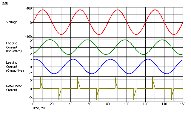
Figure 1 - Voltage & Current Waveforms For Different Loads
Above, we see the voltage waveform (which doesn't change) and current waveforms for three different loads. Of these, the lagging and non-linear loads are the most common. A leading power factor is unusual with any normal equipment, although it will be caused if PF corrected LED tube lights (for example) are installed into power factor corrected fluorescent fittings (i.e. if the PFC capacitor is not removed).
It's also worth mentioning that active PFC is completely incapable of creating a power factor other than slightly less than unity, with the 'slightly less' component caused by inherent non-linearities. Active PFC cannot create a lagging or leading power factor of any consequence, as it has no reactance and is unable to return energy to the power grid, as is the case with inductive or capacitive (reactive) loads. There seems to be a misconception that by somehow 'tuning' the circuit it can magically behave as a reactive load, but there's one small problem with this - the bridge rectifier at the input prevents any power from being returned to the grid.
There are many misconceptions about power factor, and none stand up to even the most rudimentary scrutiny. Unfortunately for everyone, many of these misconceptions come from engineers who should know better, but seem locked into the past where electronic loads were unknown, and CosΦ could explain everything. Not so - CosΦ is a shortcut that only works when voltage and current waveforms are sinusoidal. Power factor is defined as actual power (Watts) divided by 'apparent power' (Volt-Amps or VA). Unlike the shortcut method, this works regardless of the current waveform or phase angle, and is the only method that should be used.
If a load draws 1A at 230V, that's 230VA. If the power consumed (as measured by the electricity meter) is 115 Watts, then the power factor is 0.5, and it does not matter one iota whether the load is lagging (reactive), leading (reactive) or non-linear (non-reactive), or a combination of reactive (leading or lagging) and non-linear. I don't understand how some people keep missing this very important point, but they do, and it's confused the whole situation and a great many discussions very badly.
One simple phrase sums it up - "It's not hard, please get it right."
The most basic of switchmode supplies uses a bridge rectifier followed by a filter capacitor. This produces a DC voltage that's roughly equal to the peak of the AC voltage waveform, but with some ripple - anything up to 10V peak-peak ripple at double the mains frequency is not at all uncommon. In some cases (especially with some CFLs for example) the ripple voltage is even greater, but this also increases the ripple current in the filter capacitor(s), causing more internal heating. Remember - for a given load power, lower capacitance means higher ripple current, not less as you might have imagined.
Lower capacitance also causes the power factor to get worse, until the capacitor value is so low that the ripple voltage is very high indeed. At this point, there is no longer a passably smooth supply voltage. This makes the job of the switchmode converter so much harder - that is the part of the circuit that reduces the mains voltage to useable voltages for common electronic equipment. Where a widely varying output voltage isn't a major concern, it's common for the filter cap to be quite small, and this is standard in CFL power supplies (for example).
It's worth mentioning that if the load after the bridge rectifier is resistive (with little or no capacitance at all), the power factor is very close to unity. It's entirely possible to get an overall power factor of 0.97 or better. This is because there is only minimal current waveform distortion, so the mains current is very close to sinusoidal, with distortion typically less than 5%. This is actually the principle behind active PFC - to make the switchmode supply appear to be a resistive load.
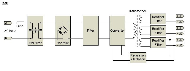
Figure 2 - Block Diagram Of Switchmode Power Supply
A generalised block diagram of any SMPS is shown in Figure 2. Although shown with three outputs, the actual number can be anywhere between one and seven or more. The EMI filter is needed to limit high frequency noise from the circuit from the mains, and is a requirement in almost all countries. It usually consists of a common-mode choke and two or more capacitors. The caps should always be rated for continuous AC duty (typically 275V AC, 'X' Class), but many cheaper circuits use ordinary 400V or 600V DC caps, in the mistaken assumption that they will withstand the applied AC. If used with 120V mains they might survive, but with 230V they will fail.
The rectifier is usually just a simple bridge, rated for the applied mains voltage and expected load current. The following filter section will either be a capacitor and nothing else, or perhaps two caps to allow 120 and 230V operation. This is the section that is replaced by the PFC circuit as we shall see further along.
The converter is well outside the scope of this article. Depending on cost constraints and output power, the converter type may be any of the following (in more-or-less ascending order of power output ....
The type of converter used also determines the way the transformer is wound, the core material, number of turns used, and whether an air-gap is included. The design of switchmode converters is a science unto itself, and pity the constructor who attempts this without the detailed knowledge needed of all aspects of the design. The design of the magnetic circuit (the transformer itself) is close to being an art form as much as a science, and cannot be trivialised or smoke will be the inevitable result. Great care is always needed to minimise leakage inductance - any magnetic flux that 'leaks' from the core increases leakage inductance, and causes unwanted spikes on the switching waveform. Because the spikes must be tamed by one means or another (usually involving 'snubber' networks), this increases losses, reduces efficiency and means that higher voltage parts must be employed.
Most converters generally operate at somewhere between 30kHz and 100kHz, although lower or higher frequencies may be also used. As the frequency increases, the transformer can be smaller for the same power throughput, but switching losses in the transistors or MOSFETs increase. For high power and high switching speeds, MOSFETs are preferred, but IGBTs (insulated gate bipolar transistors) are often chosen where extremely high power is needed.
Secondary rectifier(s) and filter(s) are also determined by the converter used, and will not be covered here either. Likewise, the regulation system and isolation - these vary widely, and in some cases there is no isolation as such. If the output(s) can operate at mains potential (such as with many SMPS used for lighting), then isolation is not needed. In many cases it's included because it makes the design easier, even though the output(s) are still nominally at mains potential.
The basis for many older (and some current) SMPS was the capacitor input filter, as shown in Figure 3. This has the benefit of extreme simplicity, but at the expense of a very poor power factor and considerable mains waveform distortion where large numbers are used or the unit is reasonably powerful.
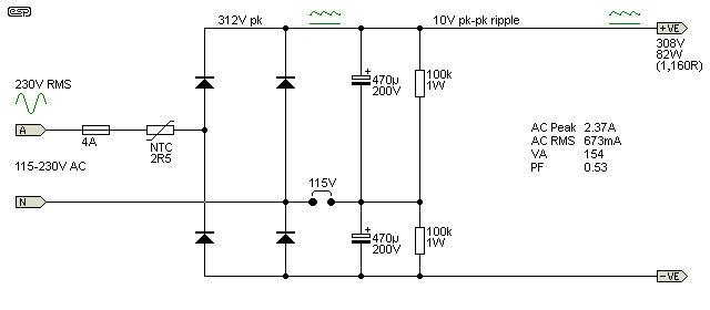
Figure 3 - Capacitor Input Filter
The circuit shown used to be a very common configuration, and is easily recognised by the mains voltage (aka 'no bang') switch. If the switch is set for 120V and the supply is connected to a 230V outlet, the result is a very loud bang, and the instantaneous demise of the power supply. The arrangement used is clever though - by using a single jumper or switch, the supply is transformed from being a simple bridge rectifier with a capacitor filter into a full-wave voltage doubler. Contrary to popular belief, a voltage doubler is not particularly inefficient, and doesn't necessarily have poor regulation.
Working from left to right, the fuse is obvious, and the NTC resistor is intended to reduce the inrush current to something passably sensible. Use of an NTC for a supply that always has close to full load works well enough, but the values typically used are too small to be really useful. Consider what happens if 230V is applied, and it's switched right at the voltage peak (325V). The caps show close to a dead short when discharged, the mains (from substation to your wall outlet) will have a typical impedance of ~0.8 ohms. Diode forward resistance can be ignored. The worst case peak current is therefore ...
R = 0.8 + 2.5 = 3.3 ohms
I = V / R
I = 325 / 3.3 = 98A
Definitely not trivial. A far more sensible value for the NTC would be at least 10 ohms, but that has to dissipate more power and is more expensive, so manufacturers won't go there. Project 39 shows my solution to taming inrush current, and this is (IMO) a far better option. The extra cost means that no-one will do it in a low-cost commercial product though.
The next items to discuss are the caps themselves. There is a tradeoff between the capacitor size (which influences cost), and the amount of ripple that can be tolerated. In some cases, a specification is given for 'hold-up time' - this is how long the supply can run if there is a momentary interruption to the mains. Longer hold-up time means bigger caps, but also lower ripple voltage and a greater duration inrush current.
With the values shown, the ripple voltage is about 10V peak-peak with 80W drawn by the load (these are not exact figures). The peak mains current with a 230V supply is 2.32A, with an RMS value of 673mA. This is a crest factor (Peak/RMS) of 3.52 - compare this with the crest factor of a sinewave, at 1.414.
The capacitor ripple current is 620mA RMS, but well over 2A peak-peak. It is vitally important that the ripple current does not exceed the maximum specified by the capacitor manufacturer and that it is maintained at the lowest practicable temperature, but it seems that this is overlooked for many designs. Either that, or the applications note (etc.) simply assumes that the designer knows about such things. Based on many of the CFL and other SMPS boards I've dissected, this is a false assumption. 
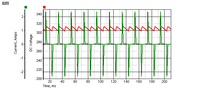
Figure 4 - Capacitor Input Filter DC Voltage & Input Current
Figure 3 shows the voltage and current waveforms (steady state) with a an input voltage of 230V 50Hz, and a load of 80W. Voltage is in red, and mains current in green. It's also worth mentioning (although it's not actually useful) that the current waveform has a total harmonic distortion (THD) of 150% or more. This means that the summed RMS value of all the harmonics is greater than that of the fundamental (note that no distortion meter can measure this, it has to be calculated or simulated).
At 120V 60Hz, the results are very similar, but of course the peak current is double and the peak voltage is a little lower (the mains impedance was set for 0.8 ohms in each case). In 120V countries, the mains impedance is usually lower than elsewhere, because the lower voltage means that current is increased by the same factor, so wiring has to be larger to accommodate the higher current.
This tends to make inrush current less of a problem with 120V mains, because the peak voltage is much lower - 170V vs. 325V. Circuit breakers are all rated for higher currents too, and a even a small NTC thermistor (such as 2.5 ohms) is sufficient to limit the worst case peak current to something a bit more sensible.
In general, householders only pay for the power they use, as so many cents per kWh (kilo-Watt hour). Any reactive (linear but out-of-phase) component is not measured, and nor is any non-linear current that isn't providing power to the load. In short, power factor (or kVA) is not measured or charged for. The supplier generally has no capacity to charge for poor power factors, however caused, because the meter doesn't register anything other than real power.
Industrial and commercial premises are treated differently though, and if the power factor is below a set limit (typically from around 0.8 to 0.95), then penalties apply for kVAr - kilovolt amps (reactive/Wattless power usage). This applies whether the load is actually reactive or is non-linear. Old style Wattmeters (the ones with a spinning disc) can't measure kVA, but the new 'smart' meters can, and it's only a matter of time before households are also charged extra for a poor power factor.
The additional charges and the point where poor power factor penalties are introduced depends on the supplier. The charges for reactive (or non-linear, although this is rarely mentioned) power in kVAr can be anywhere between a minor irritation to crippling, dependent on the energy provider's policies. These charges can only be expected to rise, because a poor overall power factor on the distribution grid means that much of the infrastructure is not being utilised to its potential.
Even if there were no financial penalties for large electricity users for producing a poor power factor, there is one important point that will be noticed ... load current! In Australia, the standard rating for a 'power point' (wall outlet) is 10A. This means that you can have 2,300W without overloading the socket, plug or cable. However, this assumes that the load has a good power factor - to obtain the full 2.3kW the power factor must be unity - as good as it gets. Only resistive loads will always give unity PF - everything else is going to be marginally less, although 0.9 or better is so close that it's academic (this means the difference between real power and VA is only 10%, and we can usually live with that).
If we assume a load with a power factor of 0.5 for simplicity, the maximum power is now limited to 1.15kW, even though the full 10A is drawn from the outlet. It doesn't matter if the poor power factor is caused by a lagging (inductive) or leading (capacitive) current, or is due to a badly distorted current waveform. The net result is that although the wiring still carries the full 10A (RMS), only half of it is doing useful work - the remaining 5A is just heating the premises wiring. Included in this is the distribution system cables, transformers and alternators - all for no purpose or benefit whatsoever!
For this reason alone, using a power supply with power factor correction makes a lot of sense. Consider the power amplifier racks used for large concert sound systems as a perfect example. There are amps that are so powerful that they exceed the rating of a standard power outlet even if the overall efficiency were 100%. If these also have a poor power factor and allowing for losses within the system, it's quite obvious that the only way these amps can function on any power outlet is because they are never called upon to provide full power on a continuous basis. When the losses considered, just one 2kW amplifier operating on a 10A outlet may exceed the average current rating for the power outlet.
By using power factor corrected power supplies, the current can be reduced to perhaps 0.5 to 0.6 of that which would be drawn without any form of PFC. This also applies to amplifiers or other systems that use a conventional mains transformer before the rectifiers and filters. While it might be assumed that the transformer improves matters, any 'improvement' is only slight, and is mainly due to the resistive losses in the transformer itself. Capacitor input filters are still just as nasty when a transformer is used, but this is commonly either ignored, or treated as if everyone (somehow) must already know this.
Ensuring that equipment has a good power factor means that the building wiring may need fewer individual circuits. There is a potential cost saving for any new installation or refurbishment of existing buildings. Especially for lighting, this could mean that the overall number of lighting circuits could be reduced, although it is still very important to make allowances for inrush current as the main capacitor charges at power-on. This is another topic altogether, and is covered in the inrush current article on the ESP website.
Low power factor also means that you cannot make full use of any backup generator, UPS (uninterruptible power supply) or PV (Photo-Voltaic - solar cell) inverter. All generating systems - mechanical (such as petrol/diesel powered) or electronic (PV or backup battery powered inverters) produce a specified voltage and are limited to a maximum current. They don't care if your load uses that current to perform real work (Watts) or not - the current limit is an absolute value. Most of these units are not rated in Watts - they are rated in VA or kVA. If your load uses in excess of the available current, then the unit's circuit breaker or other protective feature will operate. High power factor is desirable in all cases - it's simply the best way to get the full benefit from any power source - including the national grid.
EN 61000-3-2 (Europe) and IEC 61000-3-2 (US) are two of several standards that specify power factor and harmonic content of the current waveform. In the US, 'EnergyStar' requires that any lighting power supply above 25W and any other supply over 75W must have power factor correction to obtain certification. Predictably, there is no worldwide standard though, so most countries have slightly (or perhaps widely) differing requirements.
Harmonic currents, caused by non-linear loads with a non-sinusoidal current waveform, are another source of great concern to energy suppliers. There is neither the space nor is it appropriate to try to discuss this in detail here, but harmonic current is becoming a major headache for suppliers, and within industrial installations is known to cause motors to overheat and draw excessive current through power factor correction systems. Naturally, it also affects the distribution grid infrastructure, and other users connected to the supply system. Some large electricity users are required to install harmonic filters to reduce the level of these harmonic currents through to the national grid. One mine in Australia that I know of (from discussions with their electrical engineers) was threatened with disconnection if they exceeded the limits set by the supplier.
There are two main forms of power factor correction - active and passive. While comparatively simple to implement, passive PFC is not cost effective when compared to active systems. It's difficult to achieve a PF better than about 0.7 without the system becoming rather costly to produce. In all of the great many lighting power supplies I've looked at over the past few years, I've only seen a single example of passive PFC. For LED tube lights, it may be included 'accidentally' if the fluorescent ballast is left in circuit, but since most now have active PFC this is redundant.
It's worthwhile spending a bit of time on the topic of neutral current, because it's already caused several fires after the wholesale replacement of incandescent lamps with CFLs, and remains a concept that's not easy to grasp. Adding PFC circuitry solves the problem rather neatly, hence the inclusion here.
With a properly balanced 3-phase system as shown in Figure 5A, the neutral current is zero. If one or two of the phases fail (tripped circuit breakers for example), the neutral current rises, but it can never exceed the current in the most heavily loaded phase (A, B or C). Each phase to neutral gives 230V RMS, and between phases is 398V ( 230V * √3 ). This is still commonly referred to in Australia as 415V, because that's what we had when our 'official' nominal voltage was 240V (although in reality, nothing has actually changed).
Figure 5B shows what happens when three phases loaded equally with linear loads are converted to non-linear loads - for example, changing from close to 530W of incandescent lamps to 201W of CFLs. Naturally, one expects the current to be reduced, but RMS current actually increases slightly, from 2.30A to 2.37A
Power is reduced though, but the current increase is due to the poor power factor. The scary part is the neutral current, which increases from zero with a linear load to 4.11A with the non-linear load. This is 1.7 times the individual phase current, and infinitely greater than the phase current with the linear load! There is no cancellation at all, because the waveform is no longer linear, and only linear currents can cancel in the neutral wire of a 3-phase system.
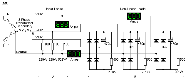
Figure 5 - 3-Phase System, Linear & Non-Linear Loads
This is an ongoing problem, because most 3-phase installations are wired with the same gauge cable for the phase and neutral conductors, although in some cases it will be smaller because everyone knows that the neutral current cancels. This may even be allowed for in some wiring regulations, although normally the neutral conductor shall not be smaller than the phase conductors. With non-linear loads, the neutral current can still be well in excess of the cable's rated current, so it will overheat. Whether or not that causes a fire is dependent on the specific circumstances.
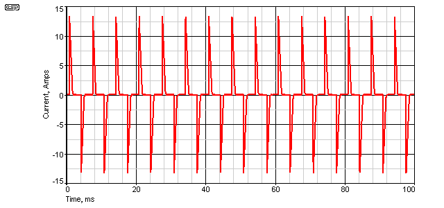
Figure 6 - 3-Phase System, Non-Linear Loads, Neutral Current Waveform
The waveform is similar to the single-phase current waveform, but note that the effective frequency is now tripled, at 150Hz (the 3rd harmonic of 50Hz). Needless to say, all other odd harmonics are also much greater than normal, and this is not a grid friendly waveform by any stretch of the imagination.
This has been just a brief introduction to the issues faced in large commercial installations, where 3-phase power is the rule rather than the exception. It is uncommon to have 3-phase power available in the home. The 2-phase system (a 240V centre-tapped distribution system) is common in the US and Canada, but is not used in most other countries. This cannot be compared to a 3-phase system.
2-phase distribution is a topic all on its own. Suffice to say that because the two phases are 180° apart, the neutral current will always cancel, provided the loads are exactly equal. It no longer matters if they are linear or non-linear.
The next two sections will now (hopefully) make some sense, and in particular you should now understand the reasons that power factor correction is so important. Each of the following sections have their own conclusions, based on the findings in each. One thing that you should understand by now is that PFC is not trivial, and its importance cannot be underestimated.
While the average user will see no change in a power bill if PFC is applied, commercial and industrial users have known for a long time that it costs them dearly if they fail to ensure their equipment is as friendly to the power grid as possible. Vast amounts of money are spent to ensure that the current drawn from the grid is as close to an in-phase sinewave as possible, because ultimately it costs less to install the PFC equipment than to pay the energy supplier's 'kVAr' surcharges.
It's worth noting that only odd harmonics are permitted above very low levels, because the presence of even harmonics signifies an asymmetrical waveform that has a DC component. Any power supply that imposes DC onto the mains will not pass compliance testing, because the effects have very serious consequences for the grid infrastructure and other users.
So, that finishes the introductory section of a hopefully easily digested foray into the mysterious world of power factor correction circuits.
See 'Further Reading' below for some in-depth material. Naturally, IC makers will always use their own devices in application notes and 'handbooks', but the information provided is excellent in both suggested documents. Both go into considerable detail and have several demonstration circuits, but also have good introductory info as well.
 Part 2 - Passive PFC
 Part 3 - Active PFC
Further reading ...
 Main Index
 Lamps & Energy Index
| Copyright Notice. This material, including but not limited to all text and diagrams, is the intellectual property of Rod Elliott, and is © 2012. Reproduction or re-publication by any means whatsoever, whether electronic, mechanical or electro-mechanical, is strictly prohibited under International Copyright laws. The author (Rod Elliott) grants the reader the right to use this information for personal use only, and further allows that one (1) copy may be made for reference. Commercial use in whole or in part is prohibited without express written authorisation from Rod Elliott. |