
|
|
| Elliott Sound Products | Power Savers |
 Main Index
Lamps & Energy Index
Main Index
Lamps & Energy Index
First and foremost, if you are unsure about what power factor refers to and how it affects the current drawn from the mains, please read Power Factor - Reality first. It will help you to understand the concepts so that what you read here makes some kind of sense.
More and more often lately, we see glowing reports on TV and in the popular press about the latest inventor who's managed to come up with a device that will save you anything from 25 to 35% on your electricity bill. We should not be alarmed (apparently) to discover that most of the 'inventors' of these revolutionary products seem to be uneducated and are unattached to any research arm of a university or similar. Almost all advertised 'power savers' on the Net are a scam - 100% of plug-in 'power savers' are a scam - no exceptions.
When people buy these things, they may well be 100% convinced that they are saving money and their bills are lower. There are likely to be three effects that make it appear that they are getting cheaper power. Firstly, there's the well known and documented placebo effect, where the belief is so strong that the user will be utterly convinced that they are saving money - even if the reverse is true. Secondly, having installed the device and wanting to see lower usage, the owner will change usage habits - probably without realising they've done so. Finally, no-one wants to look like a fool, so they'll tell you it works to save face. If it didn't work, they've been taken for a ride and no-one likes to admit they've been scammed.
While backyard discoveries are certainly possible, it's very unlikely that anyone who owns no more than a digital multimeter and a $30 power meter from the local electronics store will be able to compete with large labs that specialise in the accurate measurement of power. Huge sums are invested to obtain relatively small gains in some cases. (see footnote) My own equipment is considerably more sophisticated than that used by most of those who claim to be able to reduce your electricity bill, yet they persist regardless.
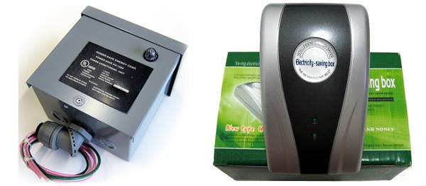
A Couple Of Typical 'Power Savers' ... That Don't
The two 'power savers' shown above are fairly typical. There are two different types - hard-wired into the meter box or plug-in. Neither work, but you obviously don't lose as much money on the smaller and cheaper plug-in types as you do with those that must be wired in by an electrician. Don't be concerned about the plug-in units not being 'powerful' enough. Since none of them actually work as claimed, just buy the cheapest unit you can if you absolutely must throw some money away. Some of them are truly remarkable - for example the small plug-in device ("Electricity Saving Box", right image above) that cannot save you a single solitary cent with loads up to 15kW! Others are much more powerful, and will save you twice as much  .
.
I bought one of the units shown on the right, so it could be pulled apart and photos taken of the insides. Fear not, I paid less than $6.00 for it, and it's worth that to be able to show readers exactly what they get. I also left negative feedback for the seller because he's selling goods that don't work as claimed. I knew this even without seeing the unit.
To some extent, I think that many of these 'inventors' may actually believe that their device works, but this is because they completely misunderstand the concept of power, power factor, apparent power, reactive loads and non-linear loads. This is a very complex field, and one that power companies are well aware of - but not because it will save the residential consumer a cent. Consumers everywhere are charged for actual power (kWh meters measure only the real power consumed, not the reactive component), and 'power savers' will result in real savings that range from negligible to negative.
Power companies use large scale 'power savers' (power factor correction) to correct for poor power factor, because a low power factor means that they cannot fully utilise their infrastructure to deliver chargeable power to consumers. This increases the system losses and the cost of distribution, and reduces profits. Power companies have used the technology that the fraudsters will call 'revolutionary' for years - power generation and distribution has been going on for over 100 years, and you can be certain that they have overlooked very little that will improve the efficiency of delivery.
As with all things, there are compromises (some very significant), but there is no new technology, and you can be certain that backyard inventors are extremely unlikely to compete on the scientific level. The vast majority either don't know what they are talking about or are lying, as we will see here. Expect to see references to NASA and PhD engineers who were involved in the development of the 'power saver'. Really? I didn't think that you'd need NASA or a PhD to put a capacitor in a box  .
.
Others claim that their lack of training or tertiary education is a 'benefit', because their thinking is not constrained by formal boundaries. Be this as it may, without exception the 'inventors' of these 'power savers' really need the formal education so they could understand why they don't work. Some even point out that the power utilities do use power factor correction, and if it works for them it must work for you, the customer sucker. They don't understand how an electricity meter works, and that these devices do not affect power, and no amount of flowery text or falsified demonstrations will change that.
A great many of these fraudulent sellers will appeal to the green lobby, and try to tell you that without their box you are needlessly consuming precious resources and ruining the planet. I argue that making, shipping and installing these devices will cause far more damage to the planet than not using them. Since they don't work, they are 100% planet hostile. Corrected power factor does benefit the electricity provider, but only if it's done properly ... these boxes do nothing properly.
As discussed further in the conclusion, no major electrical goods manufacturer or supplier sells one anywhere, and they really do have the wherewithal to develop the product properly if there was any reason to do so. They don't sell them for one simple reason - they don't want the embarrassment of prosecution for selling goods that don't do what they claim. These frauds are largely the territory of websites and ebay, often so the seller can disappear in a hurry if needs be. If you still need convincing, read on ...
 | Note that power companies and universities the world over are looking for tiny incremental
improvements to the power grid components. A saving or improvement of 0.1% is less than trivial to almost all households, but could result in huge savings
for a power company. The equipment used by the 'power saver' brigade would be unable to measure such a small change reliably, yet we are expected to
believe that they can do in the home workshop that which cannot be done by massively funded research labs. This alone should be enough to convince you
that they are charlatans.
In all cases throughout article, I will place 'power saver' in quotes - this is done to indicate that it is a slogan that bears no resemblance to reality. |
Many of the charlatans flogging their crap non-products will really try to mess with your head. They will say that all the sites that criticise their products are just being negative, and offer no positive information, claim that all you read is negative, negative, negative. Some will go so far as to say that those who criticise are "serial complainers, have a negative outlook on life, and should be avoided" - you should know instantly that you are reading a marketing con job. They are telling you to keep away from those who will tell you the truth, and they don't like the truth!
Testimonials are worthless - there is rarely (if ever) any proof that the testimonials are real. Anyone can write glowing testimonials for their own products, and attach random initials and a 'state of origin'. Likewise, anyone can use a bit of psychology to make a seemingly persuasive argument. Favourite comments are that their device has had design input from PhD engineers, NASA, etc.
Another technique you might see can be very persuasive - it will be pointed out that scientists said that manned flight could never work, that many of Leonardo da Vinci's inventions were dismissed but worked perfectly when tested properly (my emphasis), and that exactly the same applies to their 'power saver'. Everyone who says their device doesn't work "will never tell you what does work - these are just negative people with nothing to offer".
So, what does work to save power? Switching off appliances that aren't being used, using high-efficiency lighting, only using major energy-guzzlers when needed (don't run a dishwasher half full, for example) and reducing the use of air-conditioning. In other words, to save power you need to use less of it. Installing a box with a capacitor and LED in it won't reduce your power consumption one iota!
In my book, these are really the lowest of the low con artists. Their psycho-babble can be very effective, especially to the layman who doesn't understand the principles of power factor. As soon as you see anecdotal 'evidence' of the effectiveness of a 'power saver', assume that you are looking at a potentially quite sophisticated con-job, and the only skills the seller has are in creating psycho-babble, not in electrical engineering. There is one site in particular that's a stand-out in this department, but I won't provide a link because that will only increase the fraudster's web ranking.
On the (100% fraudulent) website for the 'Lectro Saver', I found the following (rather hilarious) quote ...
"I have been a licensed electrician for nearly 15 years. Quite some time ago I was working for a home owner doing a large renovation along with several other contractors. Everyone has several power tools running nonstop (drills, saws, lights, etc.)
After working for a few days I had stopped to check the electric meter to ensure everything was ready for inspections when I noticed that since I started the job there were only 1500 watts used over several days. I began to wander how could that be? With all these power tools being used it should have been WAY more than that!"
Our 'electrician' was then told about the 'Lectro Saver', and was "sceptical at first". Well, I'm sceptical now, because any electrician knows that meters do not show watts, they show kWh (kilowatt hours). The entire site and everything on it is bullshit! Like all 'power savers', this is a fraud. They don't work, and never will. As for the 'electrician', he's either as dumb as a sack of hammers or (and perish the thought) the entire quote is simply made up. Everything claimed has exactly zero credibility! I rather like that he "began to wander" - hopefully off into the distance never to be seen again.
Expect to see claims that "this technology was invented by none other than Nicola Tesla", or "was developed by NASA", amongst many others. More bullshit - the principles of power factor correction have been known for a long time, and these boxes cannot (and do not) make any difference whatsoever to your electricity bill. Another specious claim is that they "clean up dirty electricity" and "make your power more stable". Again, they do no such thing. Inside the box is a small capacitor (usually around 2µF), an LED and a couple of resistors. There's nothing else, and the fact is that using one of these may be a serious fire risk, and it will increase your power usage by a tiny amount (the power used by the resistors and LED).
This is a topic that is very poorly understood. Even a great many engineers will get it wrong, especially if they have only ever dealt with motors and transformers (large or small, but only when non-saturated!). It is only fairly recently that we have seen a proliferation of non-linear loads, where the voltage and current waveforms are not the same. Note that a partially saturated transformer presents a largely non-linear load.
It is absolutely essential that all measurement instruments used for the measurements described here (or elsewhere) are all true RMS reading. Standard (average responding, RMS calibrated) AC meters will get non-linear measurements very wrong, and will also introduce errors if the mains voltage waveform is distorted - which it is 99% of the time in most countries. Cheap wattmeters are unlikely to provide the level of precision needed to get the right answer, although they will provide an indicative reading that might be useful. Any wattmeter used must be capable of displaying real power in watts, not just the product of volts and amps (VA).
Incandescent lamps (now being banned or phased out in many countries), electric heaters (radiant or oil-filled), kettles/ jugs, toasters, electric stoves (but not induction cooktops) and electric blankets (amongst other similar appliances) are all resistive loads. These all maintain the voltage and current in phase, and have a unity (ideal) power factor. Light dimmers or other electronics that alter the current waveform will affect the power factor, even though voltage and current are in phase. This is covered in more detail below, because it's vitally important to out understanding of the topic.
The traditional calculation for power factor only considers the relative phase angle between voltage and current (commonly known as cos (cosine) φ, where φ is the phase angle), but this only applies when the voltage and current waveforms are sinewaves. So, assuming that the current is 45° out of phase with the voltage (lagging or leading), the power factor is ...
PF = cos φ = cos 45 = 0.707
If the load is inductive, such as a lightly loaded (non-saturating) transformer or motor, the power factor is called lagging - the current waveform occurs after the voltage waveform. This is by far the most common form of linear load that we see. When fully loaded both motors and transformers will typically have a power factor (PF) of 0.9 or better, but these basic machines are not often used at full load in households. Single phase motors in particular need extra power to be able to start under load, and few domestic transformers will be heavily loaded. A simple phase shifted voltage, current and power waveform is shown below.
Figure 1 - Basic Lagging Power Factor Load
Here we see a schematic of the most basic partially inductive load. The inductive part of the load impedance consumes no power from the mains nor does it produce any power (work) to the load. It is simply a necessary part of the equipment, and exists whether we like it or not. Because there is an inductive component, there is a phase shift in the current waveform, which is retarded by very close to 45°. As shown above, the power factor is 0.707
Note that other examples you might see show the inductance in parallel with the resistance. This doesn't change a thing, and the above example is just as realistic as the parallel case, although for a dynamic load the series connection is harder to work with. Work (power) is still dissipated in the resistance, and the inductance remains the cause of poor power factor. The values change if the inductor and resistor are in parallel, but the net effects are identical for the same power and phase angle.
Also shown is a capacitor that we can switch in or out of the circuit. More on this shortly. Note that numerical results are rounded, so the values shown are not exact. Unnecessary precision is pointless, because everything can change quite significantly in a few seconds with real grid-connected mains power. For example, if you calculate the exact power dissipated in the load, it's a tiny bit higher than the simulator claimed because I rounded the numbers.
Note in particular the point during a cycle where the voltage is positive while the current is negative (and vice versa). For a load to be considered reactive, this condition must exist during each cycle. If it doesn't, then the load is not reactive. This is an important concept to understand as we shall see later in this article.

Figure 2 - Voltage, Current and Power Waveforms (PF = 0.7)
The capacitor is not switched into the circuit so is not part of the measured circuit at this time. It will be connected and the results analysed a little later. Here are the waveforms for the circuit shown in Figure 1. The voltage is 230V, 50Hz and the load current is 162mA - close enough. If we calculate the apparent power (more correctly known as Volt-Amps or just VA), we get ...
Apparent Power = V × I = 230V × 162mA = 37.25 VA
As seen in the graph, the actual average power is 26.25W - we are now able to perform the proper power factor formula, which applies in all cases - not just when we have nice convenient sinewave voltage and current waveforms. Accordingly, the cosφ formula will not be used again - it is simply inappropriate and commonly gives totally wrong results with so many loads seen these days. A reactive load may be defined as any load where voltage and current have opposite polarities for part of a cycle. Look at the waveforms above and you'll see just that.
PF = Real Power (W) / Apparent Power (VA) = 26.25 / 37.25 = 0.705
In this case, the power factor works out the same (close enough) for both methods. This gives confidence that the processes and test circuits are correct. As noted, there are now two different ways to calculate power factor, but only the second version works with all supply and load voltage and current waveforms, and is therefore the only one that should be used. The old cosφ formula is irrelevant and well past its use-by date, and should be dropped from all engineering curricula forthwith.
It's worth pointing out that contrary to what you will read from 'power saver' websites, a power factor of 0.7 does not mean that your appliance is only operating at 70% efficiency. This is a common claim, and is complete nonsense. Power factor does not affect the efficiency of an appliance. Incandescent lamps have a unity power factor (i.e. perfect), yet are less than 5% efficient - the scammers won't tell you this of course.
With many electrical products, the poor power factor is well known and a capacitor is installed as part of the equipment itself. This is not common for household appliances because their overall contribution to the grid's power factor is small and there is (in general) no legislation that requires power factor correction (PFC) for domestic customers. The cap is shown in Figure 1, and when switched into the circuit it will draw about 108mA from the mains supply. This current has a leading power factor, and almost completely negates the reactive current caused by the appliance's inductance. Total mains current draw is 115mA with the capacitor connected - a reduction of 48mA. Power remains unchanged, but the current reduction can be quite dramatic. Note that when the cap is connected, the current through the load is not changed (contrary to the very silly claims of "cooler running appliances" - this simply shows that the charlatans selling their pointless boxes don't understand reactive loads).
There is now an inductive load drawing 162mA and a capacitive load drawing 108mA, yet the total is 115mA. This is because the inductive reactive current and capacitive reactive current cancel, and 115mA is drawn from the mains. The load itself continues to draw 162mA and dissipate 26.25W as before. This is seriously confusing to anyone who has not worked extensively with electrical installations, and is how the scammers have been able to convince so many people that their fraudulent devices do something that looks like magic. It is, however, completely real. You don't need to understand it, but you do have to know it happens in real circuits. Apparent power (VA) and power factor can be calculated ...
VA = V × I = 230 × 0.115 = 26.45 VA
PF = Real Power (W) / Apparent Power (VA) = 26.25 / 26.45 = 0.992
This is where the sellers of 'power savers' either confuse themselves, or they use this information to confuse you, the (intended) purchaser. They only look at the current, and see that when a capacitor is connected, the current falls. Since most people know little or nothing about electricity and even less about power factor, it's easy to see how people can be convinced that these gadgets work. Since the current is lower, then my electricity bill must be smaller too, right?
WRONG! As domestic consumers, we are almost always charged only for the real part of the power we use. Worldwide, there may be some exceptions, but I have not seen definitive evidence that anyone, anywhere, is charged for apparent power (VA). Certainly, penalties apply for industrial and commercial users who fail to correct their power factor, but in many countries it would require an act of parliament to make such a far-reaching change to the way householders are billed for their power usage.
The humble (and very well known) capacitor is the basis of nearly all 'power saver' claims, because mysteriously, the mains current falls when the capacitor is switched into the circuit. It is assumed (or claimed) that this drop in current represents a saving on your power bill. In reality, all that's been done is to improve the power factor by cancelling the reactive current. In almost all cases, your meter spins just as fast as it did before. There is (potentially) a small benefit to the power company, but only if the power factor correction is switched in and out as needed. If it's there all the time it does more harm than good!
There are some situations where adding a correctly sized PFC capacitor can save you some energy, but the savings are usually small. The capacitor(s) must be installed close to the machine with a poor power factor, and must be switched via the machine's power switch (automatic or manual). The example given here is simplified, but the principle works and is used in industrial and commercial installations all over the world.
Let's assume a load (the 'machine') that is some distance from the switchboard. It could be a motor (such as a pool pump), a bank of fluorescent lamps, a large refrigeration unit or anything else that draws a linear but out-of-phase current. For the exercise, we'll assume that the total cable resistance is 1 ohm and the unit has a power factor of 0.5, drawing an uncorrected current of 10 amps. The cable resistive loss is ...
P = I² × R = 10² × 1 = 100W
The voltage drop along the cable run is ...
V = I × R = 10 × 1 = 10V
The machine will have a much lower voltage than it should - 10V RMS less in fact. In most countries this would be an illegal installation, because the cable is clearly too small for the length of the cable run and the dissipation is much higher than it should be. However, this is an exaggerated example, so we'll ignore this minor inconvenience. (Hey, if the sellers of 'power savers' can ignore physics completely, I can ignore a higher than normal cable resistance  .)
.)
Now we add a correctly sized PFC capacitor (directly in parallel with the machine, and after the power switch). We know that the current was 10A at a PF of 0.5, so adding the capacitor will reduce the current in the feeder cable to 5A. Note that as shown above, the machine's current does not change! The capacitor supplies the 'excess' current needed, rather than having to draw it from the mains. We can now re-calculate the losses ...
P = I² × R = 5² × 1 = 25W
The voltage drop along the cable run is reduced too ...
V = I × R = 5 × 1 = 5V
This is impressive - a direct power saving of 75W (about 6.5%) while the machine is operating. The machine also has more voltage, so operates more efficiently and may not need to run as long to perform the amount of work expected because it now has closer to its rated voltage to work with. This is real!.
| However (and this is the really important part), if the PFC capacitor is installed at the switchboard, there is absolutely no change whatsoever to the power losses in the cable. To be effective, the PFC capacitor can only, ever, be mounted as close as practicable to the load (the 'machine'), otherwise only the power company benefits from the improved power factor. All cable losses remain exactly as they were before the 'power saver' was installed unless it's a PFC capacitor wired directly to the load. |
Please note that everything described above is real, although the actual power savings will usually be much less than shown if the cable run is properly sized. Nevertheless, these are real savings and if you do happen to have any motor loads at the end of a long cable run, adding power factor correction at the machine and after its switch will save you some money and make your machine run more efficiently. A box with an unknown capacitance that sells for $100-$1,500 (or more) is not the answer, but a properly sized capacitor (that should cost no more than perhaps $25) will work for you. Both require wiring by a qualified electrician, and the installation cost should be about the same.
I was (late 2012) taken to task because I have shown no lab tests. I don't need to because I know that my simulations are far more accurate than any measurement, but I have the equipment and thought that it might help, so I figured "why not". Predictably, my measurements matched simulations with almost alarming correlation. The motor is rated at 600W (about 0.8 horsepower output), 240V at 2.5A.
When I measured it (no load, exactly the same way as the 'power saver' purveyors do), it drew 2.52A at 242V (the voltage at the time) - giving 610VA. Power was measured at 170W, so power factor was a rather miserable 0.278 - pretty much as I expected. I then added capacitance in parallel until I got the best I could - I have a limited range of PFC capacitors so had to make do with what was available. The results are tabulated below, and figures are rounded as needed for consistence. Note that with 36µF across the motor, the power factor was leading (capacitive), indicating that there was too much capacitance. The optimum capacitance is around 32µF for this motor (at no load). It would have been useful if I had a couple of extra value caps to hand - with optimum correction, VA and Watts are almost equal.
Most small (almost always single phase) motors are run at relatively light loading - much less than full load. This is especially true if they are expected to start under load. Single phase motors have poor starting torque, and are almost always oversized unless there is a way to unload the motor during startup. This is uncommon, but is standard (up to a point) with air-compressors for example, because they would never be able to start with full air-pressure loading. Light loading causes a poor power factor - operated at full load, motors actually have quite a good power factor which gets better as motor size increases.
| Volts | Current | Capacitance | VA | Power | PF |
| 242 | 2.520 A | None | 610 | 170 Watts | 0.278 |
| 241 | 1.665 A | 12µF | 401 | 170 Watts | 0.424 |
| 242 | 0.956 A | 24µF | 231 | 170 Watts | 0.734 |
| 241 | 0.864 A | 36µF | 208 | 170 Watts | 0.817 (leading) |
| 242 | 0.777 A | 31µF | 187 | 170 Watts | 0.910 |
The total capacitive current (using 31µF) is 2.33A, and the motor continues to draw 2.52A - this does not change when the capacitor is added! Although this is entirely counter-intuitive, it is exactly as shown in Figures 1 & 2. The motor's reactive current is supplied by the capacitor rather than the mains supply. All claims that "motors will run cooler because of the reduced current" are complete nonsense. Any such claim simply demonstrates that the seller has no idea about electrical engineering principles, and utterly fails to understand reactance (capacitive and inductive). The interactions are baffling unless you understand exactly what is happening.
From the above table, it's clear to see that the standard 'demonstration kit' for 'power savers' will show the unsuspecting non-technical customer that the potential savings are enormous - provided the customer never gets to see the wattage!. While the current is reduced dramatically, the power doesn't change ... at all! It remains resolutely at 170W (±1W due to normal mains variations as the readings were taken). Some power meters can be set up to show VA instead of watts, and of course the average man-on-the-street has no idea that the two are completely different. Some other 'power meters' only show VA, because they don't have a voltage reading to work with. 'Power meters' that use wireless communication from a current clamp are a case in point - they don't even know the actual voltage and it has to be entered manually during setup. These are useless toys and should be avoided.
If you were shown the same test but without the real power column, it's very hard not to be convinced. The meter will quite clearly show that the VA drawn by the motor has fallen from 610VA to 198VA. Unless the potential customer understands electrical principles very well, it is inevitable that s/he will believe that what is being shown is real.
In engineering, it's common to refer to the reactive part of the current as 'imaginary', and complex mathematics use what's known as 'j-notation' to refer to the imaginary part of the current waveform. It's not really imaginary, but it performs no work itself - the reactive current allows real work to be performed. Without it, the motor I tested wouldn't work!
There's a lot more to power factor correction that the 'power savers' not only can't address, but of which the sellers are mostly completely unaware. These are covered in Section 2 below, and also Section 8, but while I had everything set up I figured that I might as well capture a couple of waveforms. These are compelling viewing, because you will see something that you didn't expect. 'Power savers' often claim that they also 'clean dirty electricity', when in reality they make it worse!
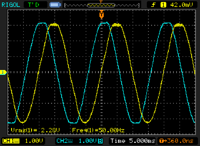
Figure 2.1 - Motor Current & Voltage Waveforms (No PFC)
Figure 2.1 shows the voltage waveform (blue) and current waveform (yellow). The RMS current shown is 2.28A (the voltage shown bottom left is actually amps), a little less than before because the voltage was lower at the time. As expected, the current lags the voltage by about 4ms (72°, for a power factor of around 0.31). Both waveforms are clean, showing little distortion other than the normal mains 'flat-topped' waveform that's typical worldwide (mainly due to non-linear loads).
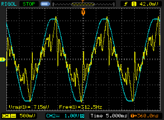
Figure 2.2 - Motor Current & Voltage Waveforms (31µF PFC)
The voltage (blue) is exactly the same as before - it hasn't been 'cleaned' in any way, shape or form. However, look at the current waveform! The distortion is clearly visible, and it no longer looks anything like a sinewave. The total current measures 715mA (0.715A), but the waveform is a complete mess. The waveform is so bad that it confused the oscilloscope's frequency counter (the fundamental frequency is 50Hz, not 312.5Hz as shown). What has happened?
The capacitor acts as a low impedance at high frequencies, with the reactance falling linearly with frequency. At 50Hz, the reactance is 102Ω, but at 500Hz it's only 10.2Ω (etc.). Harmonic current is effectively magnified and shifted in phase by the capacitor, so not only does the capacitor correct the power factor, but it also magnifies the distortion on the mains. It doesn't care if you cause the distortion or if it's caused by someone else several houses away - there are harmonic currents in the voltage waveform, and the capacitor tries (but fails) to bypass them. In the process, the harmonic currents are magnified and your electricity supply may well become noisier than it was before. So much for 'cleaner' electricity. The mains voltage waveform distortion was measured at 1.6%, but the capacitor current distortion (without the motor connected) measured 11.5%.
Total current distortion (with motor connected) wasn't measured, but is a great deal higher than the capacitor distortion alone because the same amount of harmonic current exists, but with a much lower overall current drawn. From looking at the waveform, my estimate is around 50% total distortion. Remember, capacitor current is 2.33A, but the total system current (motor + capacitor) is only 777mA. While the 50Hz component of the total current is reduced dramatically, the harmonic content is not changed at all - the full harmonic current drawn by the PFC capacitor remains unaffected.
This is the reason that 'real' PFC systems (Section 8) use a (comparatively and electrically) small inductor in series with the capacitors. Because the caps are large, the harmonic current can be so high that it causes the capacitors to fail - often in spectacular fashion. Most 'power savers' don't use large enough capacitors to cause real damage, but none that I know of include an inductor to prevent potentially destructive harmonic current. Most don't even include a fuse!
While I had the equipment set up I figured that I'd also test a so-called 'box' fan (blades fully enclosed in a plastic floor-standing housing). The majority of domestic fans use a shaded-pole motor, and these are well known for not being very efficient. The one I tested drew 48W at full power and had an almost perfect power factor. This may come as a surprise, but these motors are very basic and their impedance is dominated by the motor coil resistance (1,121Ω for the one I tested). The inductive component is relatively small, and does not contribute much towards creating an out-of-phase current component. A good indicator of the efficiency is to stall the motor and measure the power - it only rose to 53W with the fan blades locked.
Please note that all of the above is real - all measurements were taken with test instruments that are of normal workshop accuracy. I'm not a NATA registered laboratory and don't have calibration documentation, but the accuracy of my equipment is more than acceptable to provide realistic test results - especially with something as variable as a live mains system that can vary by 5% or more in a few minutes. Compared to the typical plug-in power monitors used to demonstrate 'power savers' my lab equipment is an order of magnitude better.
There's yet another trick that has been used to produce power savings. If the voltage is reduced slightly, most appliances will register a lower power consumption. Just as an experiment, I reduced the voltage to my motor by a factor of 1.414, dropping the mains from 240V to 170V. Just like magic, the motor showed a power reading of 76.5W - less than half! I measured the motor speed, which fell from 1497 RPM to 1488 RPM, only a small difference. That's still with no load though.
The PFC capacitor value changed slightly for maximum power factor, but that's of little consequence. However - the motor's torque and available power also fall by around half, so it may no longer be able to perform its job properly. With a reduced voltage, an electric jug will take longer to boil water, and heaters will also be less effective. The net result is that you'll almost certainly end up using more power if the voltage is reduced. Normally, any voltage reduction will be relatively small for 'power savers' that use this method, so you probably won't notice that everything takes a bit longer than it did with full voltage.
Voltage reduction 'power savers' are every bit as shonky as capacitors, and should be avoided like the plague! There are some cases where voltage reduction can be useful, but it's something that should be evaluated by an expert and used only on specific equipment that is known to behave properly and actually benefit from a reduced voltage.
You may also see variable frequency drive (VFD) systems touted as a power saving device. Although expensive, these can give good results, but must be set up properly by someone who knows the VFD system very well, and also understands your motor and its load characteristics. Incorrect setup can lead to higher power usage and/or equipment failure, neither of which is likely to save you money.
Cheap (relatively speaking) VFD systems will use a simple non-linear power supply that will cause a poor power factor because of the non-linear current waveform (see next section). This load cannot be corrected by PFC capacitors, but will generate large harmonic currents in the mains wiring circuit. The risk these harmonics pose is described (and shown via an oscilloscope trace capture) above, so while you may save some power you still create a bad power factor that negatively affects the grid and mains supply infrastructure.
While inductive loads are common, a far more common load in modern households is non-linear. Light dimmers are a good example, but many other products use switchmode power supplies (SMPS). PCs, microwave ovens, inverter air conditioners, small appliance chargers, compact fluorescent lamps, LED lamps are just a few examples. While some of these SMPS use power factor correction, most don't at this stage. You will notice that without fail, every single demonstration of a 'power saver' shows it reducing the current drawn by an ordinary motor or perhaps a fluorescent lamp.
What you won't see is a demonstration of the unit 'saving' power drawn by a computer or a dimmed incandescent lamp. There is a very good reason that they stay well away from these, because their device has zero effect, although in some instances it may make things worse. There are huge numbers of non-linear loads in most households these days, and in some cases you may not even see a traditional electric motor. Air conditioners and some washing machines commonly use electronic speed control for the motors, so they are no longer directly connected to the mains. Between the power outlet and the motor is a whole box full of electronics.
For low power devices, these will have no power factor correction because it adds to the cost. Larger units use a system called active power factor correction (PFC) - elaborate circuitry that ensures that the mains current is largely sinusoidal and in phase with the voltage. These circuits are complex, and have only fairly recently become economically viable due to the development of highly specialised integrated circuits that control high voltage circuitry with astonishing precision. If you are interested, see Active Power Factor Correction for a description of how this is done.
Since any home device that uses active PFC doesn't need a capacitor, the fraudulent 'power saver' can do nothing. As noted above though, all other non-linear loads are avoided too, because a capacitor cannot correct the power factor of any non-linear load. Figure 4 shows a simplified representation of a non-linear load. It's not meant to represent anything in particular, but the power, current and waveforms could be very similar to a notebook PC power supply (for example).
Figure 3 - Electronic Non-Linear Load
After the AC is rectified by the four diodes, it is smoothed by the 18µF capacitor, and the only work (energy) that is expended is via the resistance. Although it is very common to represent the real part of the load with a resistance, it could be anything from an actual power resistor (used for heating) through to rotary movement twirling fan blades or lifting an elevator full of people (although for the latter case we can safely assume the circuit will draw somewhat more than 54W ).
A resistor is shown to indicate that work is performed. Perfect (or ideal) capacitors and inductors perform no work at all - they are energy storage devices that allow energy to be added or removed without losses. Real capacitors and inductors have losses, although they can be quite small with well engineered devices.

Figure 4 - Non-Linear Load Waveforms
Note that compared with Figure 2, the voltage and current waveforms are always the same polarity - positive or negative. There is no point in the cycle where one is positive and the other negative, so the load cannot be considered reactive and no current is returned to the mains. There is no easy way to calculate the waveforms, power factor or actual power, and it is far easier to measure it. I used a simulator, but a good power meter and oscilloscope will give the same result with a real electronic load that matches the above.
Actual power is 54W, but the VA rating (Volts × Amps drawn from the mains) is 92 VA. Power factor is therefore ...
PF = Real Power (W) / Apparent Power (VA) = 54 / 92 = 0.59
If we add a capacitor in parallel with the mains this time, the current does not fall, it rises. Power is unaffected. From the perspective of the 'power saver' vendor, loads like this must be avoided, and you will never see a demonstration of their magic box reducing the current, because it cannot do so.
One thing that is critically important to understand is that the non-linear load causes power factor to be affected, even though the voltage and current are nominally in phase. This is something that even many electrical engineers seem to have problems with, and many forum arguments have raged over this very topic. The simple fact is that anyone who claims that non-linear loads do not adversely affect power factor is wrong, and I don't care how many university degrees they have - they are still wrong.
| While it is claimed by 'experts' from one end of the Net to the other, a diode bridge and capacitor filter as shown in Figure 3 is not a capacitive load, and does not cause a leading power factor. Look at the current waveform (green) - it's not a sinewave, and does not resemble a sinewave in any respect whatsoever. Nor is it leading the voltage waveform - peak current does occur before peak voltage, but that is irrelevant because it does not satisfy the criterion for a reactive load! Only when both voltage and current waveforms are sinewaves of reasonable purity and both voltage and current waveforms show opposite polarity at some point during a cycle (look at Figure 2) can the load be considered reactive. You can see that although the voltage waveform has become negative, the current waveform is still positive (and vice versa). Only when this condition is met can the power factor be reactive (leading or lagging). When one of the waveforms (typically current) is nothing like a sinewave, then phase angle is totally irrelevant to real power. There is no imaginary part because there is no reactive element, and no current is returned to the grid ... there can be no return (reactive) power because it's blocked by the diodes, so there is no leading power factor. Voltage and current are always the same polarity, so the load is not reactive. Period. This is a fact - anything different that you may read, see or hear is wrong, regardless of who claims it. |
You will also see claims where the vendor fraudster talks about "excess power" coming into your home, and other unmitigated drivel. I have seen claims that this 'excess power' causes appliance failure, and one of the lunatics selling this nonsensical junk claims that a single (36W) fluorescent lamp draws 300W without their magic box. What utter rubbish! Oh yes, it also has a "protruding wave device" (sic), whatever on earth that might be. Perhaps he forgot to zip his fly. It supposedly "protects your appliance from producing excess power and/or power surges". I call this word salad. It also appears to be contagious, as I see there are now many 'power savers' with this ... 'feature'.
A quote (verbatim) - "Protruding wave device can protect the equipment and prevent current protrude wave." Hmmm. Is that good?
Almost all of the latest generation 'power savers' are connected directly to the home switchboard, and their capacitance is across the AC line continuously. There are several things wrong with this, the first being that the 'power saver' has absolutely no idea of how many inductive loads are connected, and indeed there may be none at all.
The capacitance remains across the mains at all times, and continues to draw mains current with a 90° leading power factor. If there is no reactive (inductive) load in use, the power company will experience a leading power factor that is as bad or worse than the normal lagging power factor they expect. If enough of these silly devices were used, the power company might possibly find itself with an uncorrectable leading power factor at some times during the day - this is actually worse than they expect because most existing equipment can't correct for a leading power factor.
The purveyors of these magic boxes will never show the full mains current drawn when the motor or other load they use is disconnected. Why? Because it would show a continuous current from the mains even when nothing was turned on. They know that they can't have it both ways ... the box can't reduce your bill when stuff is connected, but have no effect when it just draws current by itself. No-one would fall for that, so the current drawn by the capacitors in the box is never mentioned.
Something else they don't tell anyone is just how much capacitance the box really has. If it's too much, their demonstrations will fail because the measured current will go up instead of down, so you can be fairly sure that the capacitance is selected to match the equipment actually used for the demonstrations. Even assuming that you have an inductive (phase shift) power factor problem, what are the chances that the magic box will be exactly right to bring the power factor back to unity?
How does the box even know that your load is connected so it can do its work? The answers are predictable - there is only a small chance that the box will provide the exact correction needed to obtain unity power factor, and it is simply connected to the line permanently whether it's needed or not.
One twit did (perhaps accidentally) disclose that his unit has a 6.8µF capacitor - roughly correct for a twin 36W fluorescent lamp fitting. It was also disclosed that the only other things in the box were a simple 5.1V DC power supply and a pair of LEDs. Strangely, there was no mention of any "protruding wave device" (sic) - which would presumably be nothing more than a metal oxide varistor spike suppressor. How impressive.
There remains a serious problem. Exactly how much capacitance do you need to get a power factor of unity? This depends entirely on how much reactive current is drawn by your appliances at any given time. A fixed capacitance (as used in most 'power savers') will only work for a constant reactive load of around the same reactance as the 'demonstration' load. If the load is turned off, then the correct amount of capacitance needed falls to zero - the cap must be switched out of circuit, otherwise it is creating a poor leading power factor ... probably all the time.
If we use the example shown in Figure 1, we know that a capacitance of 1.5µF is correct. A 6.8µF cap (for example) would increase the total mains current to 393mA - more than double the current drawn by the load with no capacitor at all! This current has a leading power factor, and cannot be corrected by the power companies. If you paid for VA instead of Watts (as the scammers imply), adding the 'power saver' would more than double the cost of operating this appliance. When the appliance was turned off, with 230V 50Hz mains the 'power saver' would still be passing 490mA of reactive current (112.7VA) for no reason whatsoever.
Obviously, if the 'power saver' has more capacitance, it will draw even more reactive current. Around 50µF of capacitance would be my expectation for a so-called 'high power' unit for 230V, and perhaps 150µF for 60Hz/120V. Those will draw a current of 3.61A (830VA) at 230V/50Hz or 6.8A (816VA) at 120V/60Hz. The cap has to be bigger for 120V/60Hz operation, but the reactive losses will be similar.
Is this still looking like a good idea?
One very common claim is that much of the current drawn by a reactive appliance is 'wasted'. This is not the case at all - it is actually used by the real (resistive or in-phase) part of your machine to produce work ... actual power. If the current through the machine is reduced, so too is the available power. This is where the whole argument about motors 'running cooler' falls apart at the seams.
Look again at Figure 1. The current through the load is 162mA, and the real and imaginary (reactive) parts are in series. It doesn't matter if the PFC cap is connected or not - the machine draws 162mA regardless. This means that the current through the resistive and reactive parts of the circuit is the same, as this is the only possible current path for a series connection. It's easy to calculate the power dissipated in the 1,000Ω (1k) resistor ...
P = I² × R = 0.162² × 1,000 = 26.25W (close enough)
If the PFC cap "made the machine run cooler" it would have to reduce the current through the machine, and this would reduce the real power. A clearly silly premise that does not happen. The full current drawn (162mA) is required and used by the load - none of it is 'wasted'.
When a capacitor of the correct value is connected directly across the motor, the overall mains current is reduced as we saw above, and the extra current needed by the inductive part of the load is provided by the capacitor instead of the mains wiring. The current demand of the machine itself is unchanged, but we've tricked the circuit by adding the cap so that the reactive currents (inductive and capacitive) cancel.
We know that the laws of conservation of energy are intact, because the power drawn from the mains now simply equals the product of volts × amps (VA). The machine is no more efficient, runs no cooler, provides no more power and does not rely on 'free energy'. We have simply used science to make the overall system more power-grid-friendly.
Even though we have done the power company a real service, there is no reward for residential and most small business customers. We are charged for the power used (kWh), not the reactive component (kVAr). However, there are exceptions! Consider the following ...
If you have your own 'off-grid' solar or wind system with battery storage and a sinewave inverter, you become the 'grid' and it is important that you maximise the power factor of all inductive loads. This is done at each machine and after its power switch (manual or automatic). It cannot be done on a 'whole house' basis unless you have a sophisticated PFC cabinet that includes microprocessor monitoring and control. Silly boxes sold over the Net need not apply.
Power factor now becomes important because your inverter has to provide the full output in VA (proper inverters and alternators are rated in VA, not Watts). If your appliances have a poor power factor, the inverter still has to provide the total load (volts times amps), and its efficiency is reduced. This is why power companies have PFC at sub-stations and why they penalise industrial/commercial users for poor power factor. Householders (for the time being) get a free run.
All lighting should be low voltage DC - remember that it is extremely difficult to correct non-linear loads such as mains (AC) powered CFLs, but LEDs with DC is easy and power factor does not apply to DC power systems.
One of the hot topics at the moment seems to be 'dirty electricity'. Compact fluorescent lamps seem to be singled out as a major generator of dirty electricity according to some websites, but according to other believers it can come from anywhere. The claimed effects are astonishing, and range from 'general malaise' right through to cancer. There are even meters that purport to show just how 'dirty' one's electricity is supposed to be, and any number of people will give you all manner of 'advice' as to what should be done.
It goes without saying that there is absolutely no proof one way or another, and there are no official measurements, standards or limits - any noise on the mains can be deemed 'dirty', depending entirely on who is telling the story.
At least one 'power saver' claims that it will eliminate 'dirty electricity', and shows a wholly unconvincing before and after graph that allegedly demonstrates what the unit does. The 'graph' is almost certainly hand-drawn, and shows nothing that makes the slightest bit of sense. This doesn't stop the lunatics selling the unit from proclaiming the benefit though. This particular unit's website even has an explanation for power factor that is wrong in almost all respects ('good' amperes and 'bad' amperes - good grief!).
According to the 100% non-scientific drivel seen on websites, a 'bad' amp is the reactive component that performs no useful work. Those who sell these fraudulent products completely ignore the fact that the 'bad' current is simply a fact of life in the way the machines work. It is cured (by real engineers) by adding capacitance directly in parallel with the machine itself - after the power switch! Installing an overpriced box at the switchboard achieves nothing useful for the vast majority of the time, and will not save you a cent. The overpriced box at the switchboard will cheerfully draw 'bad' amps, 24 hours a day, 7 days a week, but we don't talk about that.
Claims for 'cleaning' the incoming mains are specious - yes, a capacitor and optional surge suppressor devices (called Metal Oxide Varistors (MOVs)) will remove some high frequency noise from the mains, but the 'cleaning' effect will be rather small in almost all cases. To be able to 'clean' the mains effectively means that the device in parallel with the incoming mains should have an impedance that's no more than the line impedance for noise - preferably much less. The problem is that no-one knows the impedance of the mains for noise signals, because it will be different for virtually every installation.
Many electricity suppliers use something called 'ripple control' which is used to control the load at the customer premises. Ripple control is still used extensively in Australia to control off-peak hot water systems and under-floor heating (for example). If the 'power saver' works too well, it might conceivably render the ripple control systems ineffective - that would be an unexpected consequence that most users would consider unacceptable. Presumably, none of the 'power savers' cleans the mains well enough to remove the ripple control frequencies, and I would fully expect that they would be just as (in)effective removing other noise as well.
This was just too priceless, and I had to include it in full ... "There are a few Power Saver models on the market but they all work along the same principle. They store the electricity inside of it using a system of capacitors and they release it in a smoother way to normal without the spikes. The systems also automatically remove carbon from the circuit which also encourages a smoother electrical flow. This means that you will have less power spikes. More of the electricity flowing around your circuit can be used to power your appliances than before."
Removes carbon ??? What utter nonsense is this? I have never read such drivel in all my life, and this is meant to be taken seriously.
However bad some of the complete nonsense you have seen before might be, the following takes the cake! The paragraph is taken verbatim from a PDF entitled "Is the Earthwise Power Saver a Scam or Not?". After reading this snippet, you be the judge ...
The forth technology is Line Harmonics - Electricity is a little bit like a stream of water. It flows around the house looking for something to charge or run. Over time, electrons can bank up like rocks in a stream. Line harmonics smooths out the electron flow (or moves the rocks out of the stream) meaning that when moving throughout the circuits it flows better, and less electricity needs to come through the meter to get power to all of the circuits in the home.
"It (electricity) flows around the house, looking for something to charge or run." Really? Are these cretins serious? "Electrons can bank up like rocks in a stream" ... what utter rubbish, and quite possibly the worst metaphor I've ever read. Needless to say, the above is but one of many claims made in the toilet paper, sorry, 'document' that is highly suspect. Don't believe a word these thieves tell you - it's all lies. They also make a point of criticising engineers and others who say that they are thieves and liars. It's very difficult to call them anything else ... at least anything that's fit for general publication without a language warning.
A favourite claim is that by using the 'power saver', your appliances will run cooler and last longer. As noted above (see 'Wasted Current'), this is unmitigated horse feathers - no form of reactive power factor correction changes what happens inside the machine. Not one iota! All that is changed is the current drawn from the mains, the machine changes the power factor as a result of having a reactive element - an external capacitor does not and can not change the relationship between voltage and current inside the machine itself. If this happened, it would be quite absurd - adding a capacitor in parallel with a device would completely change the way the machine actually works - a ludicrous proposition at best, especially considering that the AC mains represents an extremely low impedance voltage source.
| However ... in some cases there might be a very small improvement, but generally very limited in any residential/small business environment. If the mains is especially noisy and contains significant harmonic currents, a small number of motors might run warmer than expected. This is uncommon in residential systems, and it is generally unlikely that you would ever notice. Needless to say, large industrial/commercial systems will be different, but they require a proper engineered solution, not a pissant little box bought from an internet seller. |
All sellers of these fraudulent devices are either clueless believers or calculating thieves. There is no middle ground here, none of the devices work at all for 99.99% of residential customers, and industrial or commercial users would be penalised for creating a leading power factor whenever the motors or uncorrected fluorescent lamps fittings are not in operation (these are two of the main causes of poor power factor). However, most fluorescent 'troffers' (as they are known in the industry) and battens used in commercial or industrial installations already have PFC capacitors installed!
Not long after this article was first published, I was contacted by a chap who works with real industrial power factor correction systems [5]. These are not silly toys, but serious cabinets intended to correct the power factor to prevent (or at least mitigate) power company penalties for unacceptable phase angles on the grid. One of the things that is a real concern is harmonic current, caused by non-linear loads.
If this current is high enough, it will exceed the PFC capacitor ratings and cause failure. This can (and sometimes does) result in a fire in the PFC cabinet, despite measures taken to limit the high frequency current to safe limits. Typically, an inductor is used in series with the capacitor, so the total impedance rises for high frequency harmonics on the power line. Typical sources of these high frequency harmonic currents are variable frequency drives, large (and older style) switchmode power supplies, uninterruptible power supplies, industrial rectifiers and many other electronic loads.
The reactance of a capacitor falls with increasing frequency, so while a 20µF capacitor has a reactance of 159 ohms at 50Hz, this falls to 53 ohms at the third harmonic (150Hz), and only 32 ohms at the fifth harmonic (250Hz). Larger capacitors have lower impedances. Adding a small inductor prevents the impedance falling so far that dangerous harmonic currents can be created at higher frequencies.
When you look at the current waveform of the simple electronic load in Figure 3 (the green trace in Figure 4), that waveform is rich in harmonics. There are specific conditions that can arise with any electrical installation where the results are best described as unexpected - very strange things happen that may not have been predicted. Problems with harmonic current is one such anomaly, and you can be fairly certain that the vast majority of 'power savers' do not consider any of the things that can go wrong. The likelihood of any of them including a harmonic current limiting inductor is exceptionally small, and the only thing that prevents excessive current is the rather modest capacitance that you can expect to find inside.
If a 'power saver' with no protective circuitry were to catch on fire and burn down your house, do you think your insurance company would just cheerfully pay up?
A second issue is possibly lethal. All 'power saver' claims include the assertion that the units draw no power themselves. This means that an essential component must be omitted - a bleeder resistor. This is connected in parallel with the capacitor and ensures that any stored voltage will be discharged quickly enough to prevent possible injury or death to anyone working on the electrical installation. It is probable that the vast majority of these units have no safety provisions at all.
If this essential safety resistor is fitted, the 'power saver' will actually consume a small power (perhaps 2-5W), 24 hours a day, seven days a week, even if everything inside the house is switched off. As a result, it will cost you money to have it connected, but will still not save a cent.
All of these risks need to be assessed, but in the end, you don't need to bother. The units don't work and will not reduce your power bill, they are comparatively expensive, so why would you ever install one?
It is important to understand that this 'power saver' technology is not new, and is done - properly - by many professional engineering companies all over the world. A photo of a professional unit is shown below, and this contains all the things that are actually needed. None of the required items are included in the toys sold by scammers.
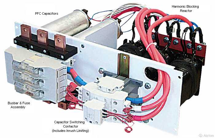
Figure 5 - Professional Rack-Mounting PFC Unit [7]
The harmonic current limiting inductor is clearly visible - see how small and cheap that would be? No, this is a serious piece of steel and copper, and is a heavy and expensive part. You will not find this inside any of the 'power savers' though, because it would cost too much. In addition, the design of the inductor is critical. It must never create a resonant circuit with the capacitor(s) at any odd multiple of the mains frequency, or it will create potentially dangerous voltages and currents. Harmonic blocking inductor design is a science unto itself, and a mis-calculation could have disastrous results.
Likewise, you won't find any sophisticated computer-based controller that switches units such as that pictured in and out of circuit as required to maintain the best possible power factor. The unit pictured uses contactors (very big relays) to switch the caps in and out as needed, but some other systems use solid-state switching. The point here is that the capacitance is adjusted as needed to optimise the power factor. It's not just a shiny box that connects directly across the mains and is left there permanently.
Power factor correction is real technology that's simply been hijacked, used in a manner for which it was never intended, cut down, cheapened and lied about. It's probably a fairly easy sell too, because very few people know enough about electricity and distribution systems. This makes them easy prey, because demonstrations will appear to be real. Certainly looking real enough to fool Australian TV stations who aired shameless Public Relations company footage showing how these frauds will "save you money".
The unit shown in the photo above is made by Alstom, and is sold in Australia by IDP Industrial Products. This has nothing in common with the 'power savers' you see offered, this is part of a real industrial solution, and is engineered to perform its task.
The backlash against the TV station 'infomercials' has been excellent, with many people complaining bitterly about their promotion of fraudulent products. It's reprehensible that TV services would put this drivel to air without bothering to check the facts first. As noted in the references section, Australia's government watchdog has prosecuted the sellers of 'power savers', and no doubt will do so again if another pops up. If only ebay (and other online sellers) could also be stopped.
First and foremost, I can prove and demonstrate every single claim I have made, with reasonably high precision instruments, a simulator, and other sophisticated test equipment. I have described each simulated test and physical measurement with more than sufficient information for anyone to duplicate what I've done, and I have made no general assumptions. This is all actual and demonstrable science, and does not rely on hyperbole, lies or twisted logic. Capacitors connected across the mains do not 'store energy for later use' any more than they can provide free energy.
It's hard to know for certain if those selling these devices either clueless and truly believe that they work (this actually seems plausible) or they know full well that they don't and are simple charlatans who want only to separate you from your money. Either way, the devices don't work and won't save you money. They will cost you money though, for purchase and installation, and for decommissioning prior to you obtaining the promised refund (hopefully, but don't hold your breath). Electrical safety concerns should be enough to ensure that no-one ever installs one of these pointless boxes.
If the premise that you pay for reactive current were true, then installing one of these devices would cost you far more to run (continuously) that you would pay without it. The reason is simple. You may have a couple of motor loads that run for a few hours each day, and the 'power saver' might (might) reduce the current drawn by a small amount.
However, the rest of the time, the 'power saver' is still connected, and is drawing its own reactive current ('bad' amps according to one supplier) continuously. If the device uses a 20µF capacitor for example (50Hz 230V mains), it will draw 1.44A ('bad' amps) continuously, 24 hours a day, 7 days a week with what's known as a leading power factor.
For 60Hz 120V mains, the cap might be 40µF (yes, I'm guessing, but my silly guesses are just as good as their silly guesses). This will draw 1.8A (also 'bad' amps of course) continuously.
The constant leading power factor may even annoy the supply authorities to the extent that they could demand that the 'power saver' be removed forthwith or they will disconnect you from the grid. This is especially true if it interferes in any way with ripple control apparatus that may be installed in your meter box (this may also include so-called 'smart meters').
The charlatans claim that we pay for the 'bad' amps drawn by our appliances, but strangely we don't pay for the 'bad' amps the 'power saver' box creates. This conundrum is easily avoided by never disclosing that the device draws any current - all demonstrations are carefully conducted to ensure that we never see the 'bad' current drawn by the PFC capacitor. Expect to be told that this is 'German Engineering' or is from some other advanced country (the US is also a favourite for those outside the US, and don't forget the input from NASA and PhD engineers ). The implication is that it must somehow be 'good' if engineered in (insert impressive sounding country) - presumably as opposed to Outer Mongolia for example. You will find these cons on websites all over the world, and ebay is riddled with them (but will take no action it seems, even though this is a well known fraud).
You have every right to be highly suspicious - these devices do not work, and claims that industry has been using them for years is simply false. Industry is expected to install complex and expensive equipment that provides full monitoring and adjusts itself to provide an acceptable power factor back to the grid - it's a lot more sophisticated than a box with a light emitting diode and a couple of capacitors!
One of the unmitigated fraud-merchants in Australia claimed that he worked with the CSIRO - a claim that has been discounted as the CSIRO has never endorsed the product or worked with the person involved. If these morons can't even tell the truth on TV, what is the chance that their 'product' is genuine? In case you haven't figured it out, the answer is "none!" .
In short, if the device simply plugs into a power outlet, or is wired into your switchboard without input and output connections, it cannot possibly work as claimed. Some devices are wired in series with the equipment being controlled, and some of these might have some validity under certain limited circumstances. There is a class of device that supposedly monitors the power and adjusts the voltage so that the motor (and these systems only work with motors) gets the power it needs and no more. Personally, I'd be very wary indeed - the available information is sketchy, and I'd be very concerned for the health of my motor(s) if they are forced to run on a reduced voltage. Most appliance makers have been building their equipment for a long time, and I'd trust their engineers over an unknown website owner and/or backyard 'inventor' every time.
As a final comment, consider that if these devices actually saved power, then major electrical goods outlets, electrical wholesalers and big department stores would be selling them. The big electrical goods suppliers would never let an opportunity like this pass - they would be crazy to let such a product be sold through shonky websites and ebay and not cash in themselves if there was any chance that they worked. However, you can't buy one from any of the major retailers - anywhere. Nor are power companies giving them away as they did with compact fluorescent lamps ... There must be a reason.
That reason is simple - they all know that the products are a con, and they don't save anyone (including the power company) a cent. If they were to sell this rubbish, they would be prosecuted by the consumer protection bureau of every major country where they were sold (there has been one known exception to this, where a 'power saver' unit was sold but quickly withdrawn by a major retailer). The shonky website operators and ebay sellers can simply vanish or declare their company bankrupt when ordered to repay the people who have been sucked in by the false promises.
If you still think they work, I have this really great bridge for sale ...
- Site gone, but you can buy the domain name.
Link marked with an asterisk (*) is the Australian Competition & Consumer Commission (Australian Government) website.
The list of scammers is obviously severely cut down and is intended as an example. There are thousands of sites on the Net, all making similar pointless and false claims.
It seems that there may have been a bit of a stoush between the first two scammers (7 and 8) listed above. Various forum sites and newsgroups have references to differences of opinion, right up to breach of confidentiality. What can possibly be confidential? The scam is well known, the use of capacitors is well known and that fact that they don't work is well known.
Personally, I think it's really funny that scammers are fighting with each other over their scam . It's even funnier since both appear to be out of business (as they should be). I'm delighted with the outcome.
Main Index
Lamps & Energy Index