

|
| Elliott Sound Products | Alternating Polarity Clock Motors |
 Main Index Main Index
 Clocks Index Clocks Index
|
There are quite a few slave clocks appearing at auctions (both 'bricks & mortar' and online), but the biggest problem is how to drive them. Some (like the Synchronome slaves) use a pulse of current created by the master, but there are many others that require an alternate polarity for each impulse. The most prolific motor of all that uses this technique is the common quartz clock, but the method used to derive the signal is hidden from view, and lurks under a blob of epoxy resin on the printed circuit board. Even if you could see it, the IC is utterly inscrutable and nothing useful can be gleaned from it.
Making matters worse, some of the alternating polarity slave clocks expect a specific current (perhaps around 200mA), while others are designed for a particular voltage. The latter can range from a few volts to 50V or more. In reality, all of these motors expect a current - the voltage is only a requirement to ensure that sufficient current will flow to make the motor turn 180°. In some cases, you might find the coil resistance printed on the outer insulation (or elsewhere), but much of the time there is nothing at all.
This article looks at how you can determine the proper voltage and current needed to make the motor turn, and ways that the alternating polarity signal can be created. While mechanical (or electro-mechanical) systems can work very well, the master clocks that generated alternating current pulses can be extremely difficult to adjust properly. This assumes that someone before you hasn't removed the contacts and actuators completely, and that you have the correct master clock.
Here, it is assumed that you have a single momentary contact closure at the appropriate interval (30 seconds is common), and ideally that the contacts are not part of the electrical wiring scheme. Where the contacts are in series with the master clock reset mechanism and the slave clock as was typical with Synchronome master clocks, and alternative is shown. We simply use a resistor to derive a voltage from the coil current.
Note that this article only discusses the drive system to create the alternating polarity drive signal. You still need a suitable timebase to generate pulses at the timing appropriate for your slave clock. Some use 30 second impulses, and some are 1 second. Gent and Synchronome slave movements use a 30 second timebase, and the minute hand moves 1/2 a division at a time. See 1 Second Timebase for a one second version. 30s is harder to achieve, because the signal has to be divided by 30 which doesn't fit standard counter ICs.
The first thing you must do is work out what voltage (or current) you'll need to make your slave motor turn 180°. For this, you need a multimeter and a simple variable power supply. Since most simple power supplies only provide up to 12V or so, there will be many motors that will refuse to budge at that voltage. Some are designed for 24, 36 or even 48V DC operation.
Set the multimeter to the ohms range, and measure the resistance of the coil. It may range from a few ohms up to 3,000 ohms (3k) or more. If you can see the winding wire this may give you a clue - thick wire means low resistance and therefore low voltage, thin wire means high resistance and (relatively) high voltage.
 | Never, ever connect any clock motor directly to the mains unless you are 110% certain that it was designed for mains operation, that the insulation is sound (so you aren't electrocuted on the spot), and that any unknown clock motor is being run at the correct voltage. Any coil that uses thumb-screws or open connections of any kind was never intended to be connected to the mains supply. Even though the standards of yesteryear were pretty lax compared to the standards of today, at least an attempt to maintain safety was normal. |
Having taken a resistance reading, there is a reasonable chance that you can figure out an approximate voltage that will make the clock turn. Very few of the larger slave motors will turn with less than about 0.25 Watt of applied power, and few will need more than 1W. Lower resistance windings will generally require higher power. For example, if you have a motor coil that measures 3,000 ohms, you can work out the minimum and maximum voltage using the following ...
V = √ P × R Where V is voltage, P is power in Watts and R is coil resistance in ohms I = V / R Where I is current, V is Voltage and R is resistance V = √ 0.25 × 3,000 = √ 750 27V at 0.25W I = 27 / 3,000 9mA
The above is the minimum voltage I'd normally expect to provide reliable operation (rounded to the closest whole number). This coil is probably intended to be run from 36 or 48V - alternating polarity. To figure out the maximum, we use the same formula ...
V = √ P × R V = √ 1 × 3,000 = √ 3,000 55V at 1W I = 55 / 3,000 18mA
The same process may be applied to any coil, and unless the coil is very small indeed (like that in a quartz clock), pulses of up to 1W will not cause a problem if of short duration and there's a long period between pulses. A motor that's designed to operate each second can withstand less power than one that operates once every 30 seconds, so at times you'll need to make an educated guess.
If we look at another (hypothetical) motor, its coil is found to have a resistance of 12 ohms, and is reasonably large.
V = √ 0.25 × 12 = √ 3 1.7V at 0.25W I = 1.7 / 12 142mA
Or if operated at 1W ...
V = √ 1 * 12 = √ 12 3.5V at 1W I = 3.5 / 12 291mA
A normal operating impulse current of about 250mA would seem about right, from a 3V source. It is highly unlikely that such a motor would refuse to run with this voltage and current, but (assuming it's not seized of course) the only way to be certain is to test it.
As a matter of interest, the same approach may be taken with motors that are just simple solenoids (such as the standard Synchronome slave). It is important to realise that this is simply a guideline though - there were so many different types made that it is impossible to be able to provide definitive data without actually testing each and every variant. This is rather unlikely to put it mildly. In particular, spring-loaded solenoids can require a much higher voltage and current than you may imagine, and this is where a variable DC power supply comes in handy.
As for being able to work out the power that any given coil will take, I'm afraid that this is something that can only be determined from experience. The total power dissipation of any component is based on the duty cycle of the applied voltage. If voltage is present for half the time, then the power dissipation is half of what you'd have if it were there continuously. Likewise, if voltage is only present for 25% of the time, then average power dissipation is one quarter. As a very rough guide, a coil the size of a 1.5V AAA cell should not be expected to dissipate more than about 0.25W (or less if it's in a totally enclosed space). A coil the size of a C cell will probably handle 1W continuous, but it will get quite warm.
Occasionally, you'll get lucky - the photo below shows a Plessey motor assembly (1 second impulse, alternating polarity), and the coil is marked with the design voltage. If only this were more common, it would make life so much easier for those who are unfamiliar with electrical contrivances and their secret and mysterious modus operandi.
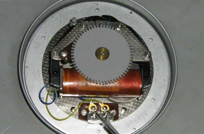
Figure 1 - Plessey 1 Second Impulse Motor
The Plessey motor is driven from the circuit described in the Build A Synchronous Clock article, except that the final drive voltage has been increased to about 22V - which is enough for reliable operation. Although the coil is marked 24V, it actually runs well on considerably less. A separate output drive circuit was needed for this motor, because the CMOS ICs used in the synchronous clock project cannot be used at more than 15V and can supply very little current.
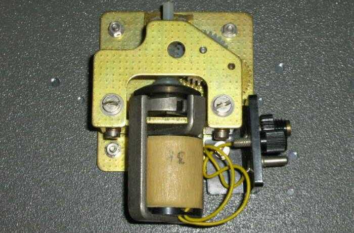
Figure 2 - Gent 30 Second Impulse Motor
The Gent motor shown above is the one that sparked this article. The slave clock was sent to me by a very nice man in the UK, who charged only the postage cost. The slaves were being stripped from a factory and would have ended up as landfill if they hadn't been rescued. The coil resistance is shown as 3k, and while it's actually a little lower this is of no consequence. While I have tested this motor at 25V, it really does need closer to 36V to be completely reliable. In reality, anything over 30V should be fine.
These motors are not critical - as described above, running them at anything between 0.25W and 1W is perfectly alright. The only thing that is critical, is that the motor is 100% reliable at whatever voltage you end up using. This will generally be somewhere between the two limits of 0.25W and 1W for at least 95% of all motors. Naturally, they should be cleaned, lubricated and checked for any problems that may cause intermittent operation.
To understand the principle of electronic (or relay) polarity reversal schemes, it may be beneficial to look at the process when used with simple switches. When all switches in Figure 3 are off, no motor current flows. If SW1 and SW4 are on, no current flows (likewise for SW2-SW3), because both ends of the motor coil are at the same voltage. SW1-SW2 on and/or SW3-SW4 on are 'illegal' states, because they will short-circuit the power supply. The normal combinations will be all off, SW1-SW3 or SW2-SW4 on - each combination forces current to flow through the motor coil in the opposite direction to the other.
Most motors only require a momentary impulse. A 1 second motor might need 0.25s on-time, and a 30 second motor may need perhaps 0.5s. The remainder of the time, there is no current flow. This is the same principle as a quartz clock motor, but their on-time is much shorter because the motor is so tiny.
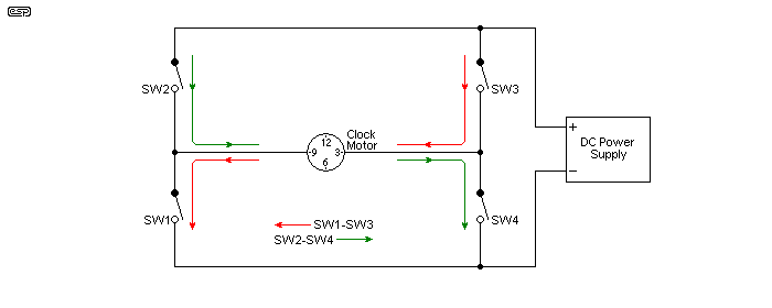
Figure 3 - Basic Polarity Reversal Technique
For those unused to electrical drawings, the switches are all shown in the 'off' state. This arrangement can be implemented with relays or specially arranged contacts in the master clock. If you don't have a master clock that includes the alternate polarity switches (or the mechanism has been butchered or removed), the least desirable way to attempt the alternate switching is to use relays. Not only do you have relays clattering away all the time, but the circuitry needed to drive them is fairly complex. While you might be able to source a specialty relay (called a bistable relay - it has two stable states), these are often difficult to obtain and can be very expensive. While they may be rated for a million operations, that doesn't mean much to a clock with a 1 second motor (it's a bit less than 12 days). Even 10 million operations is not much use, so a better arrangement is needed. (Note that in reality, most relays will actually perform hundreds of millions of operations before they wear away the contact faces, provided they are conservatively rated.)
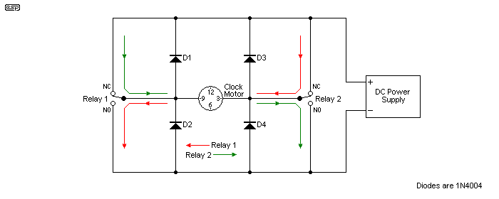
Figure 3A - Relay Polarity Reversal Technique
The above shows the wiring with relays, but the actuating coils are not shown. Depending on how the pulse generator circuit is configured, this determines the method that's needed to power the relays. The four diodes are included to absorb the back-EMF from the coil when a relay is released. Although the clock motor as shown is shorted when the relays are at rest, there's a brief period where the contacts are open, and a significant voltage will be developed across the motor coil. Left unchecked, this will eventually damage the contacts, but the diodes prevent that from happening. Each relay is operated alternately, with the 'on' time being determined by the clock motor. On average, I'd recommend around 100ms (0.1s) on-time for a motor such as that shown in Figure 2. Remember that the relay actuator coils also need diodes to prevent excessive back-EMF that may damage the switching circuits.
Naturally, I would suggest that the better arrangement uses transistors for switching. Even if my whole life hadn't been spent working with electronics, I'd still come to the same conclusion. They have a virtually unlimited life, and are perfectly capable of outlasting the equipment in which they are installed (and they regularly do just that). They are also small and cheap, so building an electronic version of Figure 3 is dead easy to achieve. In addition, transistors are available that will handle any voltage or current that any clock motor may demand, and well beyond.
While the switching itself is simple (as it is with relays), there is some additional circuitry needed to make the switches act the way that we need. There's nothing difficult about any of this, and it will form a valuable learning experience for those who build it. While it may not appear to be the case, the circuit performs identically to that shown in Figure 3A, except that transistors are used for switching rather than mechanical contacts. The only thing where you need to be a bit careful is in the selection of the transistors - they must be rated for at least the operating voltage for the clock motor. The suggested transistors have a voltage rating of 65V, which should be satisfactory for any common motor. They have a maximum current rating of 100mA, and few motors will draw that much.
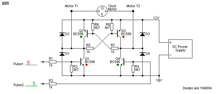
Figure 4 - Transistorised Polarity Reversal
Now, I do concede that it does look complex, but operation is quite straightforward. This arrangement is known as an H-Bridge, and is used in countless applications - power supplies, servo-motor control systems, and even audio amplifiers. There is no secret to its operation. With no input, the two clock terminals will be at the supply voltage because the resistors (R5, 6, 7 & 8) provide a path to the supply, but no current flows in the motor because both motor terminals are at the same potential. Assume that there is initially no pulse at the 'Pulse1' and 'Pulse2' inputs ...
Just like the unit built from switches shown in Figure 3, the external circuit must never apply a pulse to 'Pulse1' and 'Pulse2' at the same time. This will cause all transistors to turn on, placing a near short-circuit across the power supply. Smoke is the inevitable consequence, as the transistors die painful little deaths. The period between alternate pulses is known as 'dead-time' - a time where all circuitry is in its idle state. This is very important, because without the dead-time (which can be as low as a millionth of a second (1µs) or even less in some circuits) bad things happen. In this case, the dead time saves power being needlessly converted into heat in the clock motor coil. Most motors should work fine with an on time of around 100ms.
| Voltage | R5 and R7 (Fig. 4) | R1 (Fig. 5) | R6 (Fig. 5) |
| 12 V | 1 k | 1 k | 150Ω 0.5W |
| 24 V | 2.2 k | 3.9 k | 390Ω 2W |
| 36 V | 3.3 k | 12 k | 680Ω 5W |
All other component values remain unchanged. While I suggest the BC546 (NPN) and BC556 (PNP), any transistors with similar ratings will be fine. Diodes are all 1N4004 or similar, and the remaining resistors (not specified in the table) are as marked, and 0.25W or 0.5W. None are critical, and 5% tolerance parts are quite acceptable. This also applies to Figure 5, apart from R6. For clocks with a high resistance coil (2kΩ or more), all resistors in Figure 4 can be 10k, simplifying the bill of materials.
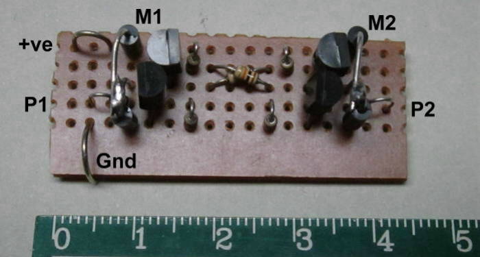
Figure 4A - Transistorised Polarity Reversal Veroboard Layout
An example of the Figure 4 circuit wired on Veroboard is shown above. At 45 × 15mm, it's far smaller than any relay switch, and it draws far less power. The drive circuit will generally only have to provide about 1mA at most to activate the motor driver. It's not immediately apparent from the photo, but the points marked 'M1' and 'M2' are the midpoints of the protection diodes for each output, shown as 'Motor T1' and 'Motor T2' in Figure 4. The circuit has been tested with the Gent slave motor shown in Figure 2 (which has a complete dial and motion works, and will be made operational in the near future).
It's also worth noting that while a relay based version of the above can be created, it will probably be more irksome to wire! You may not have fiddly electronic bits to worry about, but the interwiring of relays to achieve the required result needs two relays with changeover contacts, and these must be driven with alternating pulses in exactly the same way. The difference is that the relays draw far more power, won't last anywhere near as long, and are comparatively noisy. They will also almost certainly cost more, and you still need the diodes or the contacts will be eroded by the back-EMF spark.
Note that the process for driving a higher voltage motor (like the Plessey shown above) from a mains synchronous frequency divider is virtually identical to that shown in Figure 5 below. If you look at the synchronous clock article, the final drive to the clock motor is simply replaced by the circuit shown below. The final 4013 divider is used in exactly the same way, but drives the pulse generator (everything from Ct1 and Ct2 and to the right of the circuit).
While there are several ways this can be done, the most readily available and by far the cheapest is to use a couple of low-cost CMOS logic ICs. This method has the advantage of very low power consumption, absolute silence and (again) indefinite life. A bistable relay can be used, but as noted above, these are quite expensive, and require additional (relay) circuits to ensure that there is a 'dead time' - the period between pulses where no current flows in the motor assembly. To add insult to injury, most bistable relays require an alternating polarity to the coil - this is what we are trying to achieve in the first place!
The IC that we use to generate the alternate is called a bistable. It's also called a flip-flop (old terminology), because it flips to one state and flops to the other. Note that you cannot use an Australian sandal (thong, aka 'flip-flop') to perform this task. 
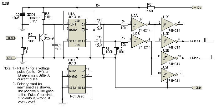
Figure 5 - Alternating Pulse Generator
A voltage pulse (between 1.5V and 12V) is applied to the 'Pulse+' input, and it is conditioned by transistor Q1. The output from Q1 is filtered with C1 to remove any noise, and is applied to the input of U1, a CMOS 4013 dual D-Type flip flop. Each pulse from the input causes the outputs to change state, so an output at 5V changes to 0V and vice versa. Positive going transitions only (from zero to 5V) cause U2A or U2B to force their output low, for a period determined by Rt and Ct. Two parallel sections of U2 are used to drive each pulse output to the circuit of Figure 4. The 10µF capacitors are standard aluminium electrolytic types, rated for 50V DC or 63V DC.
The value for Ct1 and Ct2 depend on the pulse width needed by the slave. With 10µF as shown, the impulse is just under 1 second, and this is suitable for a 30s impulse slave movement. For a 1s slave, these caps must be reduced to 2.2µF (200ms impulse) or 1µF (~96ms). If you have a 1s slave movement, it will almost certainly be quite happy with a drive pulse of less than 100ms.
Although the circuit is shown using a 12V supply, other voltages can be used. The zener diode (D1) maintains 5V for the circuitry, and the excess voltage is dropped across R6. For 12V input, the value of 150Ω is perfect, and it needs to be rated for at least 0.5W. For 24V, the value needs to be increased to 470Ω with a power rating of at least 1W (preferably 2W). The highest voltage likely to be encountered is 36V DC, so R6 meeds to be 680Ω and it will dissipate 1.4W, so a 5W resistor is recommended. This resistor will always run fairly warm, but by using a higher than necessary power rating it should last for a long time.
The transistor types you use and the resistor values needed for the Figure 4 driver circuit depend on the applied voltage and the coil current. Table 1 gives some suggestions. It's assumed that the coil will operate with a voltage of between 12V and 36V. Although an example was calculated above for a low voltage coil, these are uncommon because high current means large voltage losses in the cabling. The standard Synchronome slave is low resistance, but if you have one of those, you don't need this circuit because they don't use alternating polarity, and the slave loop is current driven, not voltage. The loop current is set with a 'ballast' resistor to ensure it's within the usable range.
 | Note: To use the above circuit for a 1 second impulse motor, you must reduce the value of Ct1 and Ct2 to 2.2µF or 1µF 63V. If the motor twitches but doesn't move, increase the value slightly. It's unlikely that you'll need to use more than 2.2µF though. No other changes should be needed. Failure to use a low enough capacitance could cause the Figure 4 switching circuit to fail ! |
Because many (most) clock enthusiasts are not into electronics, it may be felt that adding electronics to old master clocks is just not the done thing. While I agree, the circuitry described above is external, and can be removed at any time without affecting the look, feel or operation of the clock. Also, without electronics knowledge, it may be felt that dealing with small transistors and ICs is just too much hassle. (Anyone work on watches too? Now, that's small and too much hassle!  )
)
The first hurdle to overcome is to generate the alternating pulses, with or without any dead-time between contact closures. One possibility is to use mercury switches. As politically incorrect as they may be, there is no other switch that does the same thing quite as well. Mounting and activating will be something you need to experiment with, and it is not essential that the contacts break before make. There may be a period where both switches are making contact simultaneously, because we'll wire the relays differently so if both are closed it won't cause a problem. Activating the switches while removing the absolute minimum amount of power possible from the pendulum is something else that needs to be figured out for your clock.
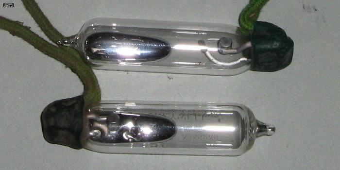
Figure 6 - Mercury Switches
For reference, Figure 6 shows a pair of mercury switches. These ones are rather large, but you may be able to get smaller versions. Assuming that you can figure out an arrangement that will work reliably and not stop the clock, the remainder of the circuit can be built. Contact is via relays, and the complete circuit is shown below. While this seems a much simpler arrangement, you won't learn much from it and it may require periodic adjustment (mainly the mercury switches and pendulum activation mechanism). Unlike the electronic version, without dead-time this arrangement cannot switch the power to the coil off during the 'resting' phase, so power consumption is higher and the motor coil will get warmer.
Energy lost from the pendulum is likely to be considerable. As the mercury moves from one side to the other, it will remove energy from the pendulum and alter the pendulum's centre of gravity. The latter is probably the most troublesome, as changing the centre of gravity of a moving body will cause a potentially serious loss of accuracy. No matter how the pendulum tilts the switch(es), it will take energy to do so, and this will stop many clocks - especially those with very small pendulum amplitudes.
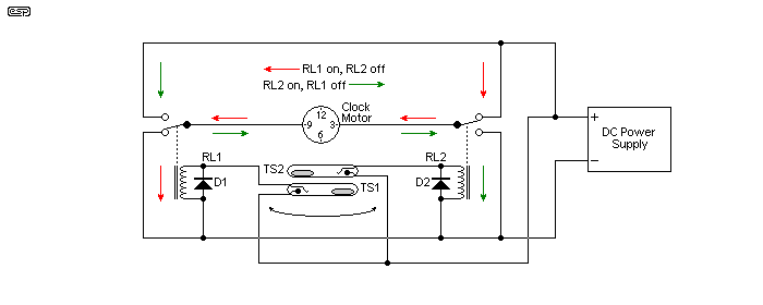
Figure 7 - Wiring Diagram For Electro-Mechanical Alternate Polarity
TS1 and TS2 are mercury tilt switches. While the above looks simple, there will be a considerable amount of mechanical work needed. The mercury switch tilt mechanism has to be attached to the inside of the case so it will be flipped one way then the other as the pendulum swings (for a 1 second impulse), and all this without removing more than a tiny bit of energy from the pendulum. While a Hipp toggle activated Gent master clock can make up for lost energy, if the impulse period is decreased, timekeeping will suffer.
A Synchronome master impulses the pendulum every 30 seconds, and while it might be possible to arrange a mechanical toggle to flip the mercury switches back and forth each time the clock impulses, I don't much like your chances. Without a bistable relay, a 30 second clock will be difficult to use with 30 second alternate slaves, and even the relay needs to be driven somehow. Remember that the Synchronome loop is normally adjusted to ~350mA, but this current cannot be obtained through any normal relay coil. Even a 5V, 125 ohm coil would require 44V across it to obtain the 350mA loop current. There are other ways of course, and the normal solution would be to use an 18 ohm resistor in parallel with the coil. When this combination is wired in series with the clock's reset coils, the voltage will need to be 5V higher than before.
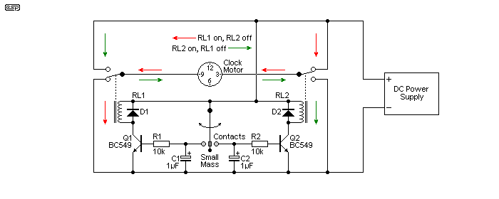
Figure 8 - Another Wiring Diagram For Electro-Mechanical Alternate Polarity
Figure 8 does exactly the same thing as Figure 7, but the relays are switched by transistors. The oscillating contact is attached to the pendulum, and is itself (possibly, but not necessarily) a pendulum, but very small and light. The contact surfaces do not need to be especially wonderful, because the transistors do the switching and even a high-resistance contact (perhaps 1,000Ω or so) will still work perfectly. If possible, use gold, because unlike silver it doesn't tarnish and will provide more reliable contact. Because the transistors amplify the tiny current they get from the contacts, they are easily able to operate the relays. If the gain of the transistors is 100, then 0.5mA into the base will cause 50mA of collector current - more than enough to operate the relays. Note that contacts should ideally be gold to ensure that they don't tarnish with age. Silver has higher conductivity, but the silver sulphide that forms is non-conductive and will cause problems.
As with anything that is attached to the pendulum, this arrangement will cause the period to change and will remove a small amount of power from the pendulum itself. This can be arranged to be extremely small though, but the details are left to the imagination of the constructor. Contact pressure must be a light as possible, but must make a positive contact at each and every swing. One possible material for the pendulum mounted contact is a short length of 400 day clock suspension spring.
If you use a contact system, I strongly suggest using gold contacts (anything above 9kt should be fine, but 18kt is less likely to tarnish). Traditionally, clock-makers have used silver because it's conductivity is so high, but that's completely pointless when you have a loop resistance that's (often well) over 100Ω. The benefit of gold is that it doesn't tarnish, so contact cleaning should not be needed - ever. Silver does tarnish, and silver sulfide (the black tarnish) is not conductive so contacts must be designed to wipe/ slide to eliminate the tarnish so that the contacts conduct current. This 'wiping' action causes wear, so silver contacts eventually have to be replaced.
While this should be simple, it is very often not. This is because a suitable power supply will almost certainly have to be built. If you are lucky enough to have a motor that will run from 12V it's too easy - just buy a 12V DC power supply and you're ready to go. 24V is trickier, and 36V more so. While you won't find too many motors that demand 48V, this is even more irksome. In general, anything above 12V DC means that you'll have to build a power supply, or fine one with the right voltage. Most of the 'odd' voltage supplies are 'open-frame' types, designed to be installed in a chassis. This will usually mean that you'll need to work with mains voltages, and unless you know exactly what you are doing, it can be very dangerous.
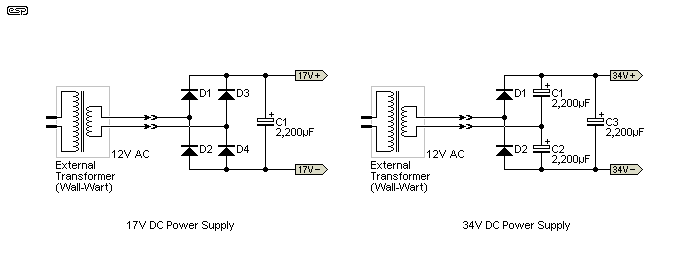
Figure 9 - 16V DC and 32V DC Supplies Use 12V AC External Transformer
The supplies shown in Figure 9 are both completely safe to build though, because they use an external transformer so no mains wiring is needed. The output voltages shown are nominal - they will vary with the load drawn by the circuitry and with variations of mains voltage. The 16V version is capable of a continuous load of at least 250mA, and can easily supply 0.5A peaks. The 32V Version will provide around 125mA continuous, with peaks of 250mA.
Both supplies require a 12V AC external transformer rated for at least 1A output. The 2,200µF capacitors should all be rated for a minimum of 35V, although C3 (32V supply) would benefit from a 50V cap. Diodes should be 1N4004 or similar. There is nothing critical about these supplies, and the available current will normally be more than you'll ever need for one or more slave dials. Be very careful not to short-circuit the output, as you may damage the circuit or the transformer.
Note that with no load, the capacitors will remain charged for a long time. To discharge the supply prior to wiring it to the circuitry, use a resistor (around 100 ohms 5W will do nicely). Don't hold the resistor in your fingers though, as it may get quite hot as the caps discharge.
AC wall transformers are not usually available in a wide range of voltages, so the available DC voltage is limited by available voltages.
For a wider range of possibilities, conventional transformers are needed, but at this stage, no specific details will be made available because of the need to work with mains voltages. If there is sufficient demand, I will add a couple of sample mains powered supply designs. The supplies shown above can also use conventional transformers, but I absolutely do not recommend that you attempt it. External transformers were specified because they require no mains wiring.
A complete discussion of power supply design is available in the article Linear Power Supply Design. It's aimed at audio applications, but the basic principles aren't changed. The current needed by most clocks is fairly modest, so you don't need to use high current transformers or bridge rectifiers. The capacitance is reduced too. Transformers come with a limited range of voltages, so every supply voltage needed will probably not be available. Some transformers are available with multiple secondary taps, so you can choose the tap that gives the closest voltage to that needed. The operating voltage for clocks usually isn't critical, so if it's a bit over or under the clock will probably still work fine.
The electronic switching system appears complex, but is low cost and very reliable. Some fiddling will always be needed, because I can't anticipate every possible issue that may be faced. Provided your clock contacts have minimal contact bounce (which causes multiple pulses) it should work faultlessly. Should you see an occasional missed pulse (the hand won't move when it's supposed to), increase the value of C1 in Figure 5. Try 100nF (0.1µF) first - you might need anything up to 1µF for a 30 second motor.
To be able to incorporate an electro-mechanical solution requires that the clock itself is modified. While this may be possible, it will be difficult to make all modifications completely reversible, so the master clock can be restored to original if required. In contrast, the electronic method can use the existing impulse(s) ... some master clocks provide a variety of different impulses. Where a 1 second slave needs to be driven from a 30 second Synchronome, a tiny contact can be attached to the count wheel detent mechanism. With transistors, the contact can be high resistance if it likes, and it won't affect the circuitry. There is no need for silver or gold, any non-tarnishing metal can be used.
Pendulum swings can be sensed using a coil and magnet, or a LED and photo-transistor can be used. These are both non-contact methods, so cannot affect timekeeping. Care is needed with the coil and magnet arrangement though, because the magnet may cause problems. The disadvantage is that single-cell power supplies cannot be used with many of the possible arrangements (especially opto-coupled systems using LED and photo detector) because of the current drain. However, at this stage all details of how to do this are up to the constructor, since there are too many possibilities to try to cover.
The use of transistors for switching in any electro-mechanical clock may not be original, but gives advantages that are not possible by using 'traditional' methods. Contacts in particular can be made to last forever, because the current is tiny and the only wear is mechanical. No sparks are generated, so there is no need for spark suppression circuits (although coils must have diodes in parallel or the transistor will be damaged).
Overall, the possibilities are almost endless, and depend on the master clock, the slave type (1s, 30s, etc.) and the operating voltage. Obtaining 30s impulses from a Synchronome or Gent master is usually easy because it is supplied as a matter of course. Obtaining 1s impulses will usually require additional contacts, and then if the slave needs alternating polarity pulses you have to go further again.
In some cases, it might even be better to build the synchronous clock circuit, especially for slave dials that accept a 1 second impulse. The mains is very stable, and you never have to worry about regulating the clock. I know it's cheating, but a nice slave that's working is far more interesting than one that sits there and does nothing.
 Main Index Main Index
 Clocks Index Clocks Index
|