

|
| Elliott Sound Products | Build a Synchronous Clock |
 Clocks Index
 Main Index
Synchronous clocks are still by far the most accurate currently available as (second-hand) consumer items. While it is certainly possible to make a quartz clock that is extremely accurate, very few manufacturers choose to do so. Because they are normally so cheap, most people would be unwilling to spend the extra to obtain guaranteed accuracy, and if such accuracy were needed, no off-the-shelf quartz clock would be good enough.
Because synchronous clocks are locked to the mains frequency, they are as accurate as the mains. The AC mains frequency is extremely accurate, because it is necessary for the power utilities to enable the rapid changeover of generating equipment. However, try to buy a synchronous clock these days. If anyone still makes them, I would expect the product to be expensive.
The question must be asked of course - why bother? The main answer is "because we can". The process is as much about learning how things work as anything else, although at the end of it we do get a clock with superb time-keeping. Whether anyone will bother with the battery backup version is doubtful, but it's included just in case.
Quartz clocks are cheap - insanely so in fact. As most people have discovered, they are fairly accurate, but can be expected to drift a few seconds each week, and sometimes a lot more. Compared to most mechanical clocks, they are very good timekeepers, but are fundamentally useless as a reference time standard.
This can change, and you will learn a lot about the digital logic used for clocks in the process.. Both 50Hz and 60Hz variants are shown, but note that things are a little trickier for 60Hz. Different logic is needed to reduce 60Hz to the standard 1 second interval used by quartz clock motors. By using a quartz motor, there are no wheels to cut or plates to make, only a bit of electronics.
Because a standard quartz clock motor is used, we can include free battery backup. If the mains should fail, the clock will automatically switch back to being a conventional quartz clock, and will revert to synchronous when the mains supply returns.
The single most expensive parts of this project are your time and the AC plug-pack (wall-wart) power supply needed to obtain the mains reference frequency. The rest consists of three cheap CMOS integrated circuits and a few other parts. It can easily be fabricated on Veroboard or similar, and a photo of one I built is shown further below.
Figure 1 shows a block diagram of the electronics. The quartz clock PCB and changeover relay are optional - they can be omitted if you don't want to use the battery backup option. Note that if battery backup is used, the clock will not show the correct time after a mains failure because there is an inevitable delay between the failure of the mains and the relay operation. Although short by design, you could lose a couple of seconds should the mains supply fail for any reason. The relay is shown energised here - the output from the new electronics is connected to the clock coil.
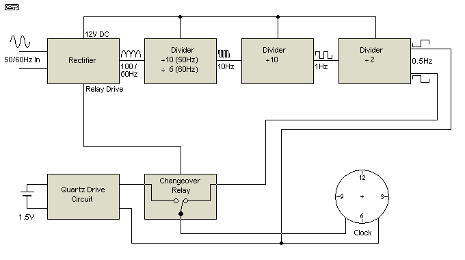
Figure 1 - Block Diagram of Mains Synchronous Clock
There's nothing difficult about the circuit. The ICs are all commonly available CMOS devices, and the current drain is minimal. The first section is the power supply, and from this we extract a 100Hz synchronising signal. For the 60Hz variant, we extract a 60Hz synchronising signal. The difference is to allow the simplest possible electronics. A 50Hz signal requires odd division ratios, and a 120Hz signal needs an additional stage - neither can be implemented with the minimum components.
The 100Hz signal is divided by 10 twice (total division is 100) to obtain a 1Hz clock signal. For 60Hz, the signal is divided first by 6 to get 10Hz, then by 10 for 1Hz. The 1Hz signal is then sent to the final divide by two stage to obtain the 0.5Hz signal needed to drive the clock motor. Each polarity of the signal (i.e. high, low) drives the motor 180°, and each 180° is 1 second on the clock dial.
The final section drives the clock motor. Most modern quartz motors are quite fussy about the applied voltage, so the maximum is limited by the series resistor which maintains the level at about ±2V - this is above the design voltage for nearly all recent quartz motors, but should work fine with most. With a supply voltage of 12V, the output of the 4013 has more than enough current to drive the motor coil, so additional parts aren't needed. If your motor proves erratic, increase or decrease the resistance as needed, and optionally add a non-polarised electrolytic capacitor across the motor coil. Somewhere around 47-100uF should be alright.
The remainder of the circuit is to provide the changeover from synchronous to quartz backup in case of power failure. A single-pole double-throw (SPDT) relay is normally held closed when mains power is available. Should the mains fail, the capacitor across the relay discharges very quickly, the relay opens, and connects the original quartz drive circuit to the motor. Three of the connections are simply joined together, since the quartz electronics are completely floating (not connected to anything else) so there is no circuit path to cause problems by this simplification.
The first task is to open the quartz clock movement. Remove all plastic gears, taking note of where everything came from. Some are very small and are easily lost, so be careful. Next, disconnect the fine wires from the motor coil. You need to exercise great care here, because the wire is extremely thin, and is easily broken. If you plan to use the quartz board for backup, make sure it isn't damaged by excess heat - you need a temperature controlled soldering iron and electronics grade resin-cored solder (preferably 1mm or less 60/40 Sn/Pb solder). Never use soldering fluid or any solder or flux that is not specifically intended for electronics assembly.
Once the coil is disconnected from the PCB, you'll need to attach slightly more robust wires. Connect them to the ends of the coil leads, and securely tape them to the coil itself to ensure they cannot separate. To use the clock electronics for backup, attach another pair of wires to the PCB to the same contact pads to which the original leads were connected. Polarity is unimportant - it varies once each second, and there is no "right" or "wrong" connection.
The quartz movement can now be re-assembled, bringing out the 4 wires through a hole drilled in the case. You need to be able to identify the leads used for the coil and the PCB - I used yellow leads for the coil and blue for the PCB. You should now test the movement to make sure everything still functions normally. Join the coil wires to the PCB wires (make sure the two pairs can't short together). Insert the 1.5V cell in its holder, and the clock should start running normally.
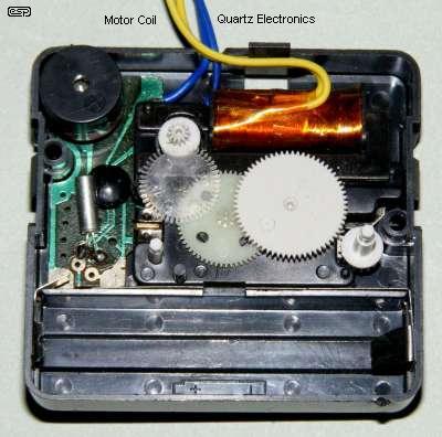
Figure 2 - Modified Quartz Clock Movement
In Figure 2, you can see the movement, with the new wires connected to the coil and PCB. Everything is back in position, ready for the back cover to be replaced. There's often not a lot of room to work with, so the job can be quite fiddly to do. As you can see, it is certainly possible though - but expect to ruin a movement or two until you get it right. They are cheap, so the financial loss is small even if you don't get it right first time.
The only critical part is the wire that comes from the inside of the coil. If you break that, there is no way to make a new connection other than rewinding the coil. The outer end isn't a problem. The enamel is easily burnt off using the soldering iron and solder should you break the thin wire, and the connection can be re-made. Losing a couple of turns in the process doesn't matter, because the coil already has more than enough turns to do the job.
This particular movement also has an alarm function. While of no use, it has been retained anyway. The alarm would remain fully functional even when running as a synchronous movement, since it only requires that a 1.5V cell be installed. The quartz coil outputs can remain unused (or can be used as power-fail backup), and the alarm is triggered by a contact closure.
The following schematics show the various parts of the synchronous electronics. The power supply is derived from an external 12V AC plug-pack transformer. These are readily available almost everywhere, and are usually priced between $15-$20. The rectifier uses common 1N4004 diodes, and the transistor can be any small signal NPN device. While a BC549 is shown, a 2N2222 or similar is perfectly suitable. C4 in parallel with the transistor is essential to prevent momentary noise spikes on the mains from causing a false pulse, and thus making the clock run fast. Because the dividers are so fast, is can be almost impossible to see very short noise-induced pulses, but the dividers will respond to pulses as short as a few nano-seconds. Just one such noise pulse per day will cause a significant error over time. D7 is a 12V zener diode, and is used to regulate the voltage to the CMOS electronics. It also protects the sensitive CMOS devices from larger mains spikes that may damage the electronics.
The dividers are both either 4017 decade counters (50Hz version) or 4018 CMOS divide by "n" counters, where "n" is any number between 2 and 10. For 50Hz operation, both counters are divide by 10, and for 60Hz one is divide by 6 and the other is divide by 10. The final divider is a 4013 dual D-type flip-flop. Only one section (U3A) is used, and the other (U3B) must be connected as shown to prevent the IC from drawing excess current. You may choose to use U3B as the active section if it makes wiring easier.
The relay circuit is fairly basic, but it works, and should release the relay in less than one second after mains failure. The relay itself can be any small relay you can get that has SPDT contacts. The current and voltage are so small that no relay is too small to be usable. The relay coil needs to be rated at 12V. The slight over-voltage presented to the relay coil is not a problem and can safely be ignored. I suspect that most constructors will omit this section entirely, as it is probably the easiest part to get wrong. Note that the relay is shown in the de-energised state in this diagram.

Figure 3 - Power Supply Circuit
The power supply consists of the bridge rectifier and the relay drive circuit. The synchronous signal take-off point depends on the mains frequency, so select the one that's needed for your country - either 50Hz or 60Hz as appropriate. Electrolytic capacitors should be rated for a minimum of 25V. The output voltage from most 12V transformers is not well regulated, so expect the voltage to be somewhat higher than claimed on the transformer nameplate. Around 14V is typical with light loading, so the DC voltage will typically be about 18V at the nominal mains voltage. Should the mains voltage increase or decrease, the DC voltage will also change in direct proportion.
R2 (nominally 560 Ohms) in series with the zener diode may need to be changed if your unregulated DC voltage is different from the expected 18V by more than a couple of volts. If the voltage is less than 16V, replace R2 with 470 Ohms, and if over 20V use 820 Ohms. The resistor value can be calculated ...
R2 = ( Vin - Vreg ) × 100
R2 = ( 18 - 12 ) × 100 = 600 Ohms (560 Ohms is the closest standard value)
The ideal current through the zener diode is about 10-12mA. Using the formula, you can determine the optimum resistance, but it's not critical. It is better to have a little too much current than too little, so always use the next smaller standard value. The maximum allowable current is about 30mA, but anything up to 20mA will be fine in practice. R1 needs to be rated at 0.5W, and all other resistors can be 0.125W or more - again, they are not critical.
There are two variants shown below - one is for 50Hz mains, and the other is for 60Hz. You only need to build the one that suits your mains frequency, not both. They have been drawn separately because there are important differences between the two. No, you can't substitute one for the other because you like it better  - you need to build the one that suits your mains frequency.
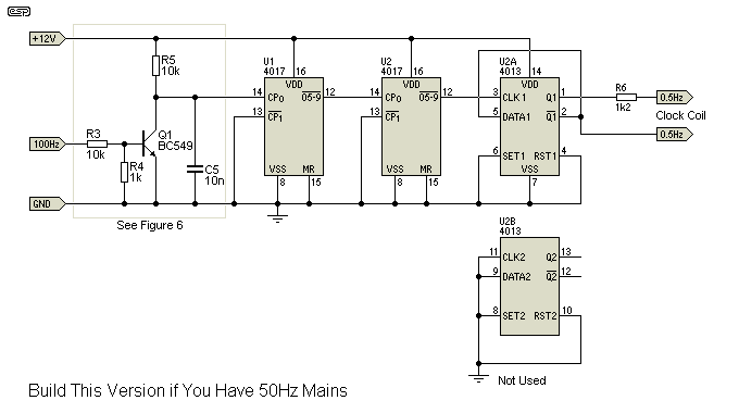
Figure 4 - 50Hz Synchronous Clock
For a 50Hz clock, two 4017 dividers are used. These both divide by 10, since the sync signal is 100Hz. This signal is derived directly from the mains, so is as accurate as your mains frequency. The 4017 is simpler than the dividers needed for 60Hz, needing few external connections to anything. Although it is theoretically possible to just leave the 4018 JAM inputs (J1-J5 below) floating, it is not recommended practice to leave CMOS inputs not connected. If unused, they should be connected to either earth (ground) or the positive supply, depending on the function of the input.
For either of these circuits, noisy mains might be a problem where you live. If this is the case (or you simply want to be certain), then use the circuit shown in Figure 6 in place of the single transistor detector shown. The simple version shown should be fine for most purposes, but if you have any doubts at all, then the more complex detector is recommended.
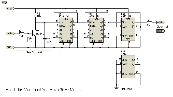
Figure 5 - 60Hz Synchronous Clock
For 60Hz, we need to use 4018 dividers, because of the requirement to divide by 6. Although the second divider can be a 4017 as used in the 50Hz variant, it's easier to use two of the same devices. This provides some consistency, and makes the job of wiring the circuit less error-prone.
The final divider for either version uses half of a 4013 dual D-type flip-flop. This provides the 0.5Hz needed by the clock motor, and also ensures that the signal has a perfect 50% duty cycle. This ensures that the second hand increments exactly once each second. The resistors limit the current into the coil - in my test clock the coil voltage was ±2V - somewhat more than normal, but perfectly alright. You might need to install a capacitor in parallel with the motor coil. If needed, use a non-polarised electrolytic of around 22uF or more - you cannot use a normal polarised electrolytic as it will fail due to the reverse voltage it receives each other half-cycle.
For a variety of reasons, some areas have a very noisy (or dirty) mains supply. This can be because of control tones sent by the supply company to switch things on or off, or just electrical noise cause by nearby machinery or even arcing somewhere. Many electric tools create a significant amount of noise on the mains, and if you are unfortunate enough to have this problem, use the circuit shown in Figure 6. The discrete transistor version is the cheapest, and takes up very little space on a PCB. Feel free to use the opamp version if you prefer.
The input waveforms are shown for 60Hz and 100Hz (derived from 50Hz). The signal is reduced in level by R1 and R2, and high frequency noise is reduced further by C1. In either circuit, the output is a noise-free squarewave that is used by the dividers to create the 0.5Hz motor drive signal.
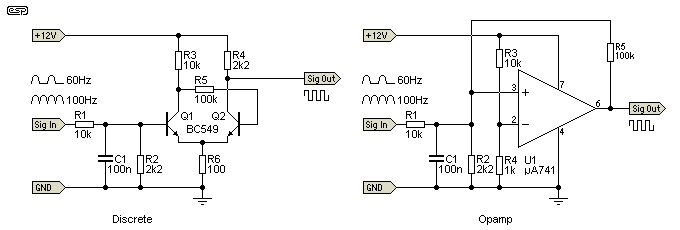
Figure 6 - Alternate Signal Detector
The circuit is a discrete transistor Schmitt trigger, and along with the capacitor (C1) will allow the circuit to give a clean pulse with even the nosiest mains. The way you'll know that you need this circuit is if your clock gains - perhaps a few seconds or minutes each day (it will usually be intermittent). R1 and R2 reduce the level of the signal (either 60Hz or 100Hz), and C1 removes some of the higher frequency noise.
The Schmitt trigger is designed so that once it operates, the voltage must change significantly before it will switch back to the previous state. Let's assume that an instantaneous voltage of 8V at "Sig In" causes "Sig Out" to go low (about 650mV). Before the "Sig Out" terminal can go high again (12V), the input voltage has to fall to around 2V. This gives a noise immunity of 6V, and this phenomenon is called hysteresis.
It is probably worth the extra few cents to add the improved detector, even if you don't think you need it. A Schmitt trigger can also be purchased as an IC, but you get 6 of them, and they don't have as much noise immunity as those shown.
The same thing can be done with an opamp as well (also shown in Figure 6), but the space taken up by the opamp version is a little more than the two transistors. Both circuits have similar noise immunity, so the choice is yours.
After all this work, you finish up with a clock that will keep extremely accurate time in almost all countries. As anyone who has a traditional synchronous clock will have noticed, they are far more accurate than most quartz clocks. The movement itself is the only let-down. Because a standard quartz clock movement will be the most commonly used, we have an entire mechanism made of bits of plastic. Fortunately, these movements are so cheap that you can keep a couple on hand to act as replacements when the original gives up the ghost.
You won't even need to modify the replacement assemblies - just exchange the modified coil for the original, reassemble the movement, and it should be good for another 10 years or so.
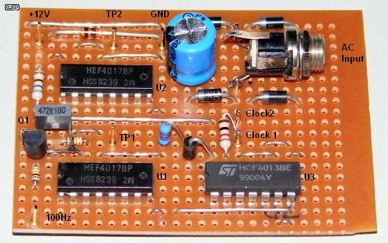
Figure 7 - Completed Synchronous Clock Electronics
The points indicated as TP1 and TP2 are test points. TP1 should show a 10Hz signal, and TP2 1Hz. The clock coil connects to the two pins indicated (Clock1 & Clock2), the 1k limiting resistor is right next to the two clock output pins. The 100Hz test point is at the top left, and drives the transistor Q1 at the top of the board. While the circuit appears complex, as you can see the entire divider chain requires very little wiring. There are three additional insulated wires on the back of the board, and what you see above is the complete circuit - including the main power supply. Power-fail changeover isn't included, and is optional.
I have built two units, with one being for a client, driving a large slave dial. The movement my customer is using will undoubtedly last far longer than my quartz-based motor ever will, but unfortunately, high quality slave movements are no longer available new. You may be able to find something on-line (at an auction site perhaps), but you need to know exactly how it's meant to be driven before committing yourself.
One alternative would be to use a quartz "skeleton" clock as shown below. Some of these are built to a reasonable standard, and much of the mechanism is made from brass or steel, so are hopefully more durable than the all-plastic variety that normally prevails. The skeleton movements are naturally somewhat more expensive, but as supplied are usually no more accurate than any other quartz clock. By converting one to mains synchronous operation, you can build a unique timepiece, but without any of the dangers inherent in old synchronous clocks (see Old Synchronous Clocks for detailed information about the problems with them). Although I already have the modified quartz movement shown above, I also have a couple of quartz skeleton movements. One of them has been used for the final build of the clock. The quartz oscillator in the one shown below is not at all accurate - it loses about 2 minutes in a week (so much for "quartz accuracy").
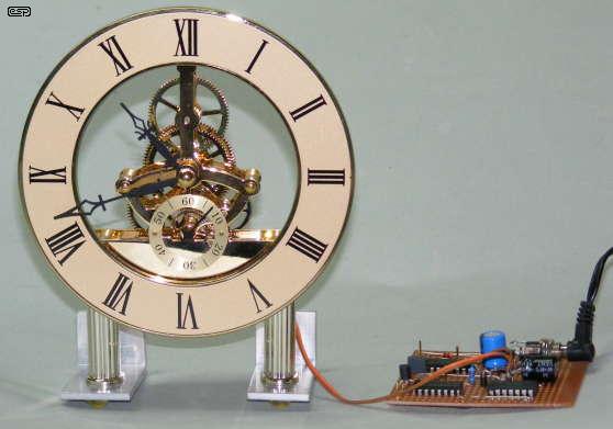
Figure 8 - Synchronous Skeleton Clock
Not yet in a case, but the skeleton clock seen here is fully operational, and was actually running when the photo was taken. The bits of aluminium attached to the legs are to keep it from falling over. Timekeeping is (of course) perfect, and it remains in sync (to a fraction of a second) with my PC clock which is in turn synchronised to an Internet time server (I use time.nist.com). Needless to say, it is also in perfect sync with two other synchronous clocks, one electronic and the other using a rewound synchronous motor and running from 16V AC for safety.
It seems that the time from my camera is pretty close to reality, since it says that the photo was taken at 10:47AM, and this is the time shown on the clock.
The technique shown here works extremely well, and is an interesting adventure into digital frequency division. There are many other possibilities - the unused section of U3 could be used to indicate that a power failure had occurred. Since the IC can easily be used as a simple latch, it may be used to illuminate a LED to show that the current time shown is not (or may not) be correct.
For those who seek the ultimate accuracy, a button can be included to hold all dividers in their reset state until the button is released. This would allow the time to be synchronised to a known accurate source to within one second or better. The reset function could even be linked to a remote control. This simple project could easily become the most elaborate quartz clock motor drive known to man, but I suspect I've already created enough complexity to last most people a lifetime.
 Clocks Index
 Main Index