
|
|
| Elliott Sound Products | Making Old Synchronous Clocks Safe to Use |
 Main Index
Clocks Index
Main Index
Clocks Index
There is a certain joy about some of the old electric (mains operated) clocks for a great many collectors. They cover a very important period in horology, and at their peak were the most accurate clocks available to the public. This remains true today - very, very few modern quartz clocks can match the overall long-term accuracy of a mains driven synchronous clock motor.
This is because the mains frequency is very well controlled almost everywhere now. It has to be, because if there are variations, it becomes extremely difficult to bring additional generating plants on-line as needed. In general, it's fairly safe to say that the exact number of AC cycles expected in each day will be produced. For 50Hz countries, this means 4,320,000 cycles per day (50Hz × 60s × 60m × 24h), or 5,184,000 cycles for 60Hz mains.
This is easily confirmed by measurement. Any mains synchronous motor clock can be set using the most accurate time standard available, and can be verified against the same standard week after week.
The whole idea of the techniques described here is to prevent old electric clocks from being scrapped. It's very depressing to see an old synchronous clock case, only to find that someone has tossed the original mechanism (most of the time, it is literally tossed out), and the case fitted with a cheap Chinese quartz movement. While purists may object to replacing the coil, if done carefully it will be a) completely invisible, b) easily reversible or c) both! There is no comparison between an old electric clock with its original movement, but modified for low voltage operation, vs. a case that's been gutted and fitted with a quartz movement.
In the majority of the examples presented here, the electric movement can either be restored to original or made to appear virtually identical to the original, with the only change being that it now runs from a low voltage and is far safer than it ever was before.
The biggest problem with these clocks is that most of them are over 40 years old, and some may be up to 80 years old. This means that their electrical insulation is almost certainly exactly the same age ... this is not a good thing. The older materials - especially those over 50 years or so - are not very robust, and early attempts at cable insulation were less than inspiring. It's not at all uncommon to find the old flexible insulation literally falling off wires, particularly if it has been even slightly warm for all those years.
To make matters worse, very few (well, almost none, actually) of these clocks had a safety earth connection, and in many cases there isn't even enough space available to fit a 3-core flexible cable. This combination of old and deteriorating insulation, lack of a safety earth, and the almost complete lack of any form of electrical safety standards means that many of the remaining synchronous motor driven clocks are extremely dangerous.
If anyone tried to sell a product with so little regard to safe practices today, no country's regulations would allow it - there would be an immediate ban on further sales and a mandatory recall. Insulation failure can cause either electric shock (up to and including death) or fire. Neither is a pleasant thought, and if we are to keep these clocks for future generations some compromises are necessary. The wiring used is known as 'Class-0', meaning that protection from electric shock is provided by 'basic insulation', and there is no provision for a protective earth. This class of equipment is allowed to exist, but cannot be used in any new product. Class I means that a protective earth is fitted, using a 3-wire lead and mains plug.

| NOTES: Consider that if metal parts of the clock are accessible from the outside (time setting knob, mounting screws, bezel, etc.) then by the standards of today it is a
requirement in most countries that all insulation be to the 'double insulation' (Class II) standard. Most old synchronous clocks qualify as Class 0 (see Wikipedia for more information), which is either banned already or being phased out, depending on where you live.
The modification suggested here converts the clock from Class 0 to what is generally considered to be the safest possible option - Class III - SELV (Safety/ Separated Extra Low Voltage). The external transformer used must be a recognised Class II double insulated type, suitable for the provision of SELV as defined by the appropriate regulations in your country (AS/NZS, CE, VDE, UL, CSA, etc.). A traditional open frame transformer usually does not comply, and must not be used. This method relies on the proper certification reserved for a listed Class II transformer. Any other component cannot be relied upon to provide the same level of safety. |
Somewhat intriguingly, this article has generated a certain amount of flak. Most people can see the benefits and appreciate the additional safety aspects, but some have claimed that a low voltage is no safer than the original (this is nonsense of course), and another claimed that the clock was 'mangled' by rewinding the coil. I do not understand how some people can be quite so blasé about potentially dangerous wiring. Electrical safety is not trivial, and if a repair is made to a customer's clock and the owner is subsequently injured, the repairer may be held liable for damages. This depends on where you live and the regulations that exist, or may simply be the end result of a litigious client.
The original coil can be retained, so originality is easily restored - it will take a few minutes work to make the change if ever necessary. By leaving the clock in its original condition, there remains a risk of electric shock and/or possibly fire. Contrary to some claims, 80 year old insulation cannot be considered to be 'high quality' by today's standards. At low voltages, the chance of an internal short circuit causing overheating or fire risk is almost zero. The maximum possible voltage across the windings is 16V - enamelled wire will withstand this forever. The same cannot be said for very thin wire, with very old enamel, subjected to the full mains voltage.
External transformers are almost always double-insulated, and to pass this standard they cannot fail in any way that could cause the secondary to become live. In almost all cases, compliance with Class II standards requires that an internal thermal fuse is fitted, so even if your low voltage rewind were to fail, the excess current will cause the transformer's thermal fuse to open.
Adding a fuse into the low voltage circuit ensures that excess current will blow the fuse, and provides protection against an over-current condition. Cheap 'Poly Switch' thermal fuses can be used at low voltages, and could easily be incorporated into the new winding if desired. The same cannot be said for a clock operating at mains voltage. The typical current draw may only be 10-20mA, and even under fault conditions this may only rise to perhaps double that figure. At that point, dissipation will be 4 times greater than normal and the coil will get very hot indeed. How do you fuse 10-20mA reliably? With extreme difficulty. Very low current fuses are available, but are expensive and not easy to get. Most fuses will take up to 1 hour to fail when the fault current is ~1.5 times the rated current.
One mitigation for electric clocks in the US is that the 120V mains is far less dangerous than 230V, as used in Australia and most European countries. The chance of insulation breakdown at 120V is reduced dramatically compared to 230V, but there is still a risk, and it could still quite easily lead to an electric shock or electrocution. For things that you, and only you, will ever work with, you may be willing to take that risk. If someone else who does not appreciate the possible danger gets hold of the item in question, then that is a different matter entirely. Many of us who work with clocks are getting on in years, and I wouldn't want my children or grand-children to be electrocuted after I'm gone. Electric clocks that are to be used should be absolutely safe ... end of story.
From a purist perspective, the clock should be kept as original as possible, but to ensure safety this isn't possible. What to do? Power leads obviously must be replaced - while a couple of ancient band-aids or some early disintegrating electrical tape might be 'authentic' for a clock of that age, they cannot be allowed to remain if the clock is actually to be used.
For clock motors that represent a genuine fire or electric shock hazard, corrective action is essential. No, the clock will no longer be original, but what's the difference between cutting a new wheel for an eighteenth century clock and rewinding the motor coil of a synchronous electric model? There's no real difference - if the clock is to function, then the repair must be made. In the case of electric clocks, the repairs must assure safety - there is no real equivalent of 'electrical safety' for a purely mechanical clock, but a parallel might be refusal to replace the original (worm-eaten) feet of an old longcase clock that subsequently falls over and crushes someone's child.
There is no good reason at all to try to retain original electrical parts that are potentially dangerous. Any parts removed can naturally be kept with the clock, so while it may be operating with safe electrics, at least the original work is kept for posterity. Doing so also allows future generations to see how things were done 'back then'. Thus we can have the best of both worlds - we have a clock that runs and is safe, plus we have the original parts that can be re-installed for 'show' at any time.
Bear in mind too that a favourite pastime of some repairers (often at the behest of the clock owner) is to install a quartz movement. If that happens, all originality and value is gone forever. The old parts will almost certainly be thrown away or deposited in a 'junk box', and a potentially valuable clock is instantly worthless.
Because of the often very cramped layout of some electrics (such as the Hammond pictured below), it is impractical to try to rewire the clock with an earth connection for safety. There simply isn't enough room to accommodate the 3 wires in a clock that was designed for two wires with barely adequate insulation. There is a relatively simple solution though, and that's to rewind the coil to operate at SELV (safety extra-low voltage). In most countries, SELV is defined as 32V AC or less, and an ideal voltage is 16V. I selected this because it is a standard voltage almost everywhere for the external power supply for intruder alarm panels. 16V AC plug-packs (or 'wall-warts') are (or should be) readily available anywhere in the world. Other voltages can also be used - simply follow the processes described, but substitute the voltage of your choice.
Rewinding the existing coil to use 16V instead of 230V or 120V does require some initial testing though, and given that some of these clocks may come to you already burned out, it may seem like a very difficult job to determine how many turns are needed to make the clock run.
It's not difficult at all, but it does require that you have access to a variable AC voltage of between 3 and 20V. A multi-tapped low power transformer can be used, or use any transformer that you have handy and a Variac™ (variable voltage transformer). The latter combination is ideal, but Variacs are fairly expensive and the cost is not warranted for the occasional synchronous clock.
| Should you follow the instructions (or make an educated guess) to get the required turns, you may discover in some cases that the new coil runs hotter than expected. If this happens, simply add more turns - an increase of 50% is likely to be quite alright. Because everything is low voltage, having a join in the middle of the coil isn't an issue, and basic insulation is more than sufficient. Any join must be soldered securely - simply twisting wires together is not acceptable, even with such a low voltage. |
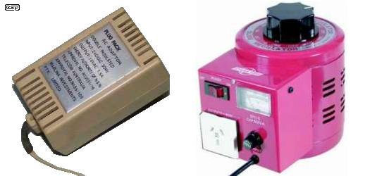
Figure 1 - 16V Plug-Pack (Left) and Variable Voltage Transformer (Right) (Not to Scale)
The transformer and Variac are the ideal combination, but you might need to get assistance. Because the cost of a Variac (or generic equivalent) will possibly exceed the value of the clock you are going to modify, pragmatism needs to be applied in generous serves  .
.
Naturally, if you are certain of your abilities and have a collection of mains electric clocks, it may well be worth your while. Note that all descriptions in this article assume 16V operation. You will need to adapt the process described to suit the different power source should you wish to use something other than 16V.
The first clock to be converted belongs to a fellow member of the clock club. I only had the motor (pictured below) - the movement and case pix were after the conversion by the clock's owner. The power lead was in extremely poor condition, with insulation crumbling and falling off the wires close to the coil. There was no insulation over the bare connections to the coil, and the mains lead was 'secured' in the case with a knot. While this used to be common, it is illegal under most wiring rules because it does nothing to prevent the lead from being twisted internally. A knot also places extreme stress on already aged insulation, and an accidental (or deliberate) hard pull could easily cause the wires to cut through the already degenerating plastic causing a short circuit.
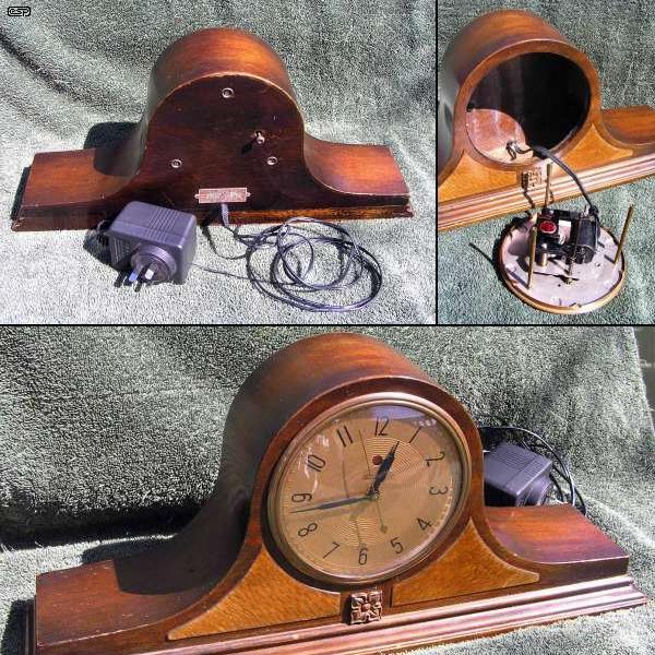
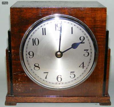
Figure 2 - Warren Telechron Clock Movement and Case (After Conversion)
The motor of chassis was unearthed - the mains lead was 2-core. While an earthed lead could have been attached, suitable mains cable that looks reasonably authentic is fairly hard to get. Cable intended for electric irons (for clothing) is usually cotton covered and would look alright, but it's considerably thicker than the lead usually used with electric clocks, and almost invariably patterned. Not exactly authentic.
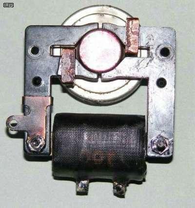
Figure 2B - Warren Telechron Clock Motor
As noted above, there was never an earth lead to the clock chassis, even though the motor has an earth lug (on the left, and obviously never used). A short (or leakage) from the coil to chassis makes the entire mechanism potentially live. This includes the front bezel, time-setting knob and mounting screws. This is unacceptable, so there are two choices.
The first is to rewire the clock using a 3-core earthed lead as described. This makes the clock electrically safe, but does nothing to address the possibility of fire caused by the motor coil overheating. While this is probably unlikely, I am unwilling to trust insulation that's between 50 and 70 years old. It is entirely possible that if an old clock did cause a fire, one's insurance policy may be cancelled because the source of the fire (the clock) was not compliant with any current electrical appliance standards. This is particularly true in the US, where UL registration (or lack thereof) is taken very seriously by insurance companies.
By powering the clock from an approved external power supply, this is mitigated because the external supply complies with all requirements, and the risk with low voltage and limited current is greatly reduced. Remember that almost no old clock is even fitted with a fuse (I've not seen one yet), so there is no protection whatsoever against excess current caused by an internal fault.
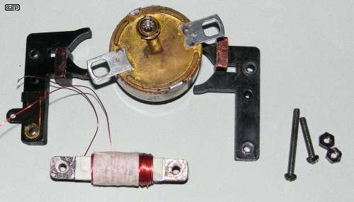
Figure 3 - Motor Dismantled, with Test Winding
Above you can see the various bits of the dismantled motor. Initial tests have been done (as described below) and the test winding is completed. It's now ready for reassembly and further tests. The magnetic circuit is very crude, and compared to a much earlier Warren Telechron motor that I have, this one was made at a time when cost was critical.
There are several ways to determine the number of turns needed to run a clock motor at a different voltage from the original design value. The method described below is good, but may be a tad complex if taken to extremes (as I did in the description). The second method also works well, but requires very accurate measurements of low voltages. It's also useful to have two multimeters that can measure AC Volts and current, but this isn't essential. You can even use guesswork, but may end up with a motor operating voltage for which no transformer is available.
If at all possible, the first thing to do is to check if the motor works. There's not much point rewinding a motor that has a sealed motor unit with seized bearings, a movement that has stripped fibre gears or other problems that make it a write-off. The existing wiring should be checked first - never just plug the clock into the mains without checking that there are no short circuits between the mains terminals or from mains to chassis. Use a multimeter to check the resistance between mains pins on the plug - for almost any clock motor, expect something in excess of 2k ohms for 230V and 1k for 120V motors. Take a note of the resistance reading, because you'll need it later.
Do not touch the clock plates or any other part of the movement while it is plugged into the mains, as the insulation may already be faulty. If smoke escapes from the motor, disconnect power immediately - it almost certainly has shorted turns.
If you are confident that you know how to take mains AC voltage and current readings without blowing up your meter or killing yourself, and you have read the warning above and accept full responsibility for anything that happens (good or bad), you can continue. Otherwise, please seek assistance, because a mistake could be fatal. Alternatively, use the method described below which does not require you to take a mains reading at all.
Another alternative (but not as accurate) is to take the power rating from the nameplate - if one exists. It's uncommon for these to show the actual power, it's generally an approximation, and is usually 'ball-park'. A reasonably typical value is 2W, but the actual power could deviate by a factor of two - either way. Assuming that you took a measurement, let's use the measured current drawn by the Telechron motor - 18mA (at a measured 240V) as shown in Figure 4.
Figure 4 - Measuring Motor Current
Beware! This requires you to make potentially lethal connections, and all connections must be insulated to prevent accidental contact. A diagram showing how to take the measurement is shown above. I cannot stress enough that if you are even the tiniest bit unsure of the procedure - don't do it. It's better to simply experiment with low voltage windings until you get it to the point where it works properly than to risk electrocution!
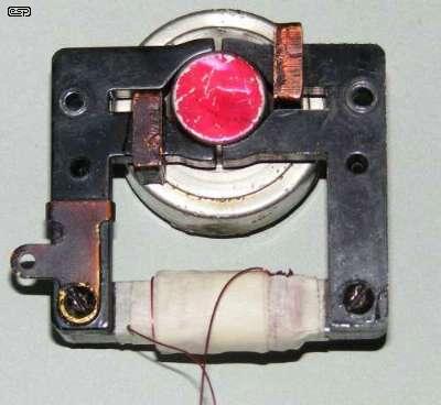
Figure 5 - Ready to Measure Motor Current in Test Winding
Current is measured indirectly, using a 1 Ohm 5W resistor in series with the neutral lead. Working with main power is never safe, but this reduces the risk somewhat. If you don't know how to determine the neutral lead, you should not attempt this procedure.
With the clock motor operating, measure the voltage across the 1 ohm resistor. You should get a reading somewhere between 15-25mV for 220-240V 50Hz motors. I can't give an accurate figure for 110-120V 60Hz motors because I don't have access to 60Hz power, but I would guess that the current should be roughly double that of a nominal 230V motor (i.e. around 30-50mA). Since the resistor is 1 Ohm, the current is simply the multimeter reading, but in Amps. If you read 0.018V (18mV), the current is 0.018A (18mA).
Remember when the resistance of the winding was taken and noted down? Well, now we will need it.
VA = V × I (where V is voltage and I is current)
VA = 240 × 0.0184 = 4.42
So, while the nameplate rating is 2W, the VA rating is 4.42VA. We can calculate the impedance.
Z = V / I
Z = 240 / 0.0184 = 13,043 = 13k Ohms (close enough)
This motor has a DC resistance of 3.9k (3,900) ohms - all of these are actual figures from the Warren Telechron motor. The real power dissipated in the motor windings (which all turns to heat) is determined by ...
P = I² × R (where R is DC resistance)
P = 0.0184² × 3900 = 1.32W
While this might not seem like much power, it will often be in an enclosed space, so even this small dissipation can result in a significant temperature rise. It is possible that we may be able to reduce it by a worthwhile amount, and we definitely don't want to exceed it if at all possible. Most importantly, we have some information about the normal running conditions of the motor. Some of the applied current is also turned into work (turning the motor), so the nameplate rating of 2W is probably fairly accurate. Not all will be, and not all synchronous clocks even have a nameplate.
If the measurements with the clock connected to the mains are not done, the current can be estimated based on the nameplate rating. If the rated power is 2W, we can calculate a passable guess at the theoretical current ...
I = ( P / V ) × 2
I = ( 2 / 240 ) × 2 = 0.00833 × 2 = 0.0166A = 17mA
The theoretical current is simply I = P / V, but small motors have a pretty poor power factor, and I multiply by 2 to allow for a power factor of 0.5 - a reasonable assumption. If the concept of power factor is completely foreign to you, don't worry too much about it. You can look it up on the Net, but it won't really help because it's actually a very complex topic. Feel free to accept my educated guess, as the result won't be too far off.
Now it's time to remove the original winding (preferably leaving it intact), and run some new tests using a lower voltage. Wrap some masking or similar tape around the steel coil insert. Remember that there are many different designs, so adapt the process to suit your particular clock motor. Now hand wind about 150 turns of wire around the taped steel. Almost any gauge of wire will do, but I suggest something between 0.3 and 0.5mm diameter. The number of turns is not critical, but you must know the exact number you wound. I used 0.315mm wire (30 SWG, or roughly 28 AWG).
Using your variable AC power supply (either the Variac + transformer or multi-tapped transformer), apply enough voltage to get the motor turning. You'll probably find it will require somewhere between 3 and 6 volts. You need to add a small amount of extra to ensure the motor will run even if the mains voltage is lower then normal, so if the motor starts to run reliably at 3V AC, the optimum voltage is a little over 4V (add around 40% safety margin).
Now, measure the exact voltage and current drawn. Use the 1 Ohm resistor again, because it's much safer for your meter to do it that way. Measure the voltage across the resistor to determine current, and measure the voltage directly across the motor - not the supply voltage! The resistor reduces the voltage applied to the motor, so you must measure the voltage directly across the motor terminals.
For the Telechron motor, this was 3.72V at a current of 1.85 amps (1.85V RMS across the 1 Ohm resistor). Don't be alarmed at the high current - this is inevitable because of the small number of turns (the motor and resistor will get very warm). From this, you can calculate the impedance in the same way as before ...
Ztest = V / I
Ztest = 3.72 / 1.85 = 2.01 Ohms
The required impedance is easily determined ...
Vr = Vold / Vnew (where Vr is the voltage ratio)
Vr = 240 / 16 = 15
Inew = Iold × Vr
Inew = 0.0184 × 15 = 0.276A = 276 mA
Znew = Vnew / Inew
Znew = 16 / 0.276 = 58 Ohms
Impedance is increased by the square of the turns, so if we get 2.01 ohms with 150 turns, we'll need ...
t = √( Znew / Ztest ) × 150
t = √( 58 / 2 ) × 150 = √29 × 150
t = 5.385 × 150 = 808 turns
t = t × Fs (where Fs is a safety fudge factor of 1.25)
t = 808 × 1.25 = 1,010
I added a safety factor by multiplying the number of turns obtained by ~1.25 to ensure there will be sufficient turns. The magnetic circuit of most motors requires very complex analysis, and basic calculations almost never work properly. The 1.25 'fudge factor' suggested is based on experience, and is unlikely to be found in any text book covering motor winding.
To double check, we can adopt a different method. We know that 150 turns were used for the test winding, and that the applied voltage was 3.72V AC. This is close enough to 40 turns per volt. Since we want to operate the motor from 16V, we therefore need a minimum of ...
t = 40 turns/volt × 16 = 648 turns × 1.25 fudge factor = 810 turns
While somewhat short of the figure calculated before, it's not unreasonable. At least we know that we are in the right area. Had the second calculation shown (for example) 1,500 turns were needed, then it is obvious that a mistake must have been made somewhere. At this point, you'd probably need to go back to the beginning and re-do the measurements.
Because there aren't that many turns, the coil can easily be hand-wound (I didn't, because I have a coil winder). The coil was rewound with 1,000 turns, using the same 0.315mm wire I used for the test. The coil is easily checked before final finishing, and because the voltages used are safe, you don't need to worry about proper insulation - masking tape is perfectly alright.
An alternative method can be used that doesn't require any connection to the mains. You will need to use 10 turns of fairly heavy gauge wire (at least 1mm diameter, and preferably bigger). Your multimeter must also be capable of reading very low AC voltages accurately, typically around 50-200mV AC. There is actually very little difference between this method and the turns/Volt calculation performed at the end of the last test, except this time we use very heavy gauge wire to minimise resistance effects in the test process.
You will need a transformer rated for at least 5A at around 5V or less. It may be possible to simply add a few turns to an existing transformer, since the voltage needed is less than 1V. Again, if you do this, the wire must be at least 1mm diameter. It is expected that most people will not have a Variac available, so we'll use resistors to reduce the voltage and current to something sensible.
For the sake of this exercise, we'll assume that you have a 5V, 5A transformer. The current need will be between 2 to 4 amps, so you need around 10 x 10 Ohm 5W resistors. These are cheap and readily available. Be careful, because they will get very hot during the test procedure. Wire the transformer, resistors and temporary coil in series as shown in Figure 5A. Initially, use 4 of the resistors in parallel to get 2.5 Ohms and a current of around 2 Amps.

Figure 5A - Alternate Test Setup
With this arrangement, see if the motor will run. If not, join additional resistors in parallel until the motor runs reliably. The idea is to obtain just enough voltage and current to get the motor operating with enough torque to run the gearing and motion work. Once the motor runs happily, measure the voltage across the motor winding - keep the lead length as short as possible between the motor coil and the measurement point to minimise errors cause by wire resistance. Note that if the motor winding gets even slightly warm it's too thin. There should be as little resistance in this winding as possible.
Let's assume that you measured 185mV (0.185V as shown on the meter). Since you wound 10 turns onto the motor, this means that you have ...
10 / 0.185 = 54 turns/V
Since you want to run the clock at 16V (or some other voltage that suits you), you therefore need ...
16V × 54 = 865 turns
As before, there is no problem using a few more or less turns that theoretically necessary, and I happen to know that 700 turns of 0.315mm wire will fit into the motor I was testing. Even though you can simply wind on 1,000 turns (or as many as will fit) and it will probably be fine, I recommend that the test be done anyway, as you will learn more about what's going on, and you may find that you need considerably more or fewer turns for some motors (especially if significantly larger or smaller than average).
Alternately, simply wind as many turns as will fit onto the former. Because the voltage is low, problems are unlikely even if you don't have quite as many turns as you should. You do need to verify that the end result runs cool enough so as not to risk insulation damage - if you can't hold the winding in your hand after 2-3 hours of operation in the clock case, it's too hot. The winding should get no more than barely warm. If it runs hot, either use a lower voltage or rewind the coil.
In particular, note the big motor voltage difference between this test process and the one described above. The reason for the difference is the resistance of the wire and the number of turns. The 10-turn method described here is obviously easier to wind, but requires greater measurement accuracy. You may use more turns if you like, but remember to keep the resistance to a minimum.
This method is reasonably easy, and does not require any specialised equipment. You do need to ensure that the test coil is wound with heavy gauge wire though, or you will get a resistive loss that will make it appear that you need far more turns than necessary.
In case you were wondering, yes, you can run the clock from a 10 turn winding. Finding a transformer with a secondary voltage of around 200mV will be a challenge though, since no-one makes such a thing. The motor I was testing when I came up with this method drew about 3 Amps at 120mV - about 360mW, but no available transformer has such a low voltage secondary. One could easily be built, but it's preferable to use a higher voltage from a transformer that you can actually buy rather than have to build it.
In general, it's best to assume that the supply voltage will be somewhat lower than the measured value. If you look at the figures for the various clocks described, you see that the new low-voltage winding resistance is between 11 and 21 ohms. The three clock motors that were rewound and measured show that current is about 300mA on average.
If the voltage drop due to resistance is calculated, it's between 3.3V and 6.3V. This voltage must be subtracted from the actual applied voltage, as it performs no work as far as the motor is concerned, therefore, the real operating voltage is from 9.7V to 12.7V. None of this matters one iota if the motor runs fine and remains no more than lukewarm.
Actual power dissipation can only be determined after the coil is wound. A very rough approximation can be done now though - this will indicate if the wire size is too small, which will cause excessive dissipation. The test coil had a measured resistance of 1.3 ohms with 150 turns, so 1,000 turns will be (ideally) 8.6 ohms. It will actually be more, because the winding length will be greater, so say 15 ohms to be conservative. Power can be calculated as before, and with 270mA and 15 ohms resistance, power is just over 1W. This is comfortably less than the original, so it should run somewhat cooler.
The final coil can be made from a heavier gauge wire if you are certain that the required number of turns will physically fit into the space allowed. Heavier wire will have less resistance, so power dissipation will be reduced accordingly. Anything less than 0.5W loss will be almost impossible to achieve though, and even up to 1.5W or so will usually be perfectly alright. The minimum possible dissipation is largely determined by the quality of the magnetic circuit - given the construction of this motor, we can't expect miracles.
Before the new coil is wound, we'll need to make a former. Because of the low voltage used, almost any available material will be fine. Suitable choices are high density cardboard (not corrugated), thin fibreglass or other plastic, fibreboard, etc. There is nothing critical about the former, only that it will fit over the motor laminations and is strong enough to stay together while the new coil is wound. Vacuum impregnation with varnish is nice, and makes the finished job mechanically quiet and look very professional, but it's not at all necessary. Remember that the clock will now be operating at only 16V, so robust insulation is not necessary.
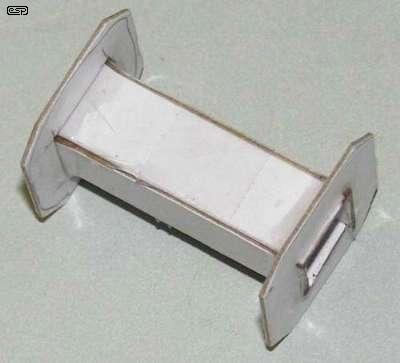
Figure 6 - New Coil Former, Ready for Winding
The new former is made from cardboard, and was lacquered before rewinding for appearance. To form the terminals, I used brass crimp lugs, flattened and bent to allow the lugs to be accessed outside the final wrapping. An overall wrap of black tape finishes off the coil, which was first soaked in varnish, then drained and baked at around 100°C for a couple of hours. The completed low voltage Telechron motor is shown below.
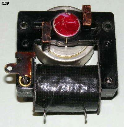
Figure 7 - Telechron Motor, Rewound for 16V Operation
Naturally, very basic theoretical calculations and reality will not coincide - this was to be expected from the outset. The measured results for the new coil after final installation are as follows ...
Coil Turns 1,000 (0.315mm wire) Minimum Voltage 10V (motor just runs) Applied voltage 16V Current 311mA DC Resistance 11.5 Ohms Power Dissipation 1.11W
This is well within the anticipated deviation from the theoretical figures above, and is a pretty good result overall. After about 15 minutes, the coil warms up a little, and DC resistance rises to 12.6 ohms, current falls to 307mA, and power dissipation increases slightly to 1.18W. Heat dissipation is still less than the original coil, so all requirements have been satisfied. Long-term power dissipation of the new coil was also tested, using the 16V AC plug-pack supply shown above. After several days continuous running the motor assembly remained barely warm, despite the fact that the measured voltage was 18V AC - this is perfectly normal.
It's worth pointing out that the resistance causes a voltage drop within the winding, and this causes the majority of the heating effect. It does something else too - it reduces the usable voltage in the coil. While a measurement shows that there is 16V applied to the coil, almost 3.8V is lost across the wire resistance ( V = I × R ) with a current of 311mA. The motor doesn't care about the voltage, only the current. and this is the primary parameter in all calculations. Although we are constrained by transformers that are designed to supply a specified voltage, fortunately it's easy to work this once we know how.
While the new version is certainly not original, it is safe to use on a day-to-day basis and runs much cooler than it used to do. Because the old coil is intact and functional, the clock can be restored to its original form at any time (for showing at an exhibition perhaps). The important thing is that the clock can be operated, and will not cause a fire or pose any risk of giving anyone an electric shock. The end result is a clock that can be used, is now far safer than it was before, and has a fighting chance that in later years will not be converted use a quartz movement. This is a common practice with old clocks that are considered potentially dangerous (or irreparable for whatever reason), but the result is an abomination. All the clock's original innards are invariably discarded and a possibly valuable clock in the future is rendered utterly valueless. The entire history of the clock simply vanishes, leaving only a case, a dial and bezel (perhaps) and a $5 quartz movement.
Give me a modified but otherwise original movement any day - if I want a quartz clock, I'll get one at the supermarket!
The Hammond clock uses a completely different type of synchronous motor, but the basic principle is exactly the same. We need to take the same measurements, and run the same initial test procedure to determine the optimum number of turns. There is a small complication, in that the Hammond uses the stray AC magnetic field to operate the alarm buzzer, but this should not affect the final result.
The measurements show that the motor coils are almost identical. The nameplate rating is again 2W, and the motor coil draws 22mA in normal use. This is such a small difference from the Telechron that it can be ignored. In addition, the coil itself is a very similar size, so the process will be the same as the previous motor. The new coil will be wound using the same number of turns, and on the same type of former.

Figure 8 - Rear of Hammond Clock Back Plate
The photo below shows the rear of the back plate. The various levers and shaft holes for the alarm and hand setting thumbwheels are visible. The remaining hole partially surrounded by a protective shield is the start wheel. Because the motor cannot start by itself, it requires a bit of help from the owner to get going.
On the photo below, the extra pieces of metal around the coil are for the alarm buzzer. The buzzer armature bridges the gap between the two, but is not able to make solid contact, so it simply rattles with the alternating magnetic field. It's not very loud, but since the clock dates back to a much quieter time I suspect it would have been quite adequate.
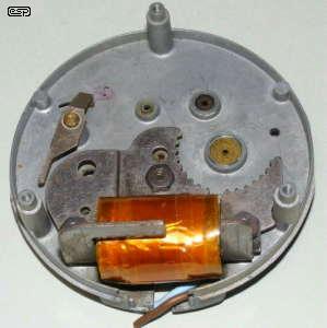
Figure 9 - Hammond Motor (Clock Movement Removed)
The synchronous motor 'teeth' are clearly visible above. Note that the motor stator only covers a 180° arc, and is basically a very crude arrangement. However, it works just fine despite the rather crude implementation. Indeed, like many such clocks, the motor is capable of outlasting the rest of the clock. Unlike some, the rest of the clock's wheels and pinions are made to a reasonable standard - this would not have been a cheap clock in its day.
To highlight the potential problems that can (and do) occur, there is a section of the diecast case that's missing - it's difficult to see in the photo, but it's on the edge of the case to the left side of the original coil. I cleaned this part of the case quite some time ago, but the missing piece was literally blown out by a short circuited lead. Needless to say, the display would have been spectacular, but the danger of fatal electric shock is obviously very real indeed. The outer wrapping on the coil was also damaged by the arc, and the original (decaying) cable was wired directly into the coil without terminals (again, due to the lack of space).
My original plan was to (attempt) to wire a 3-core lead into the clock, but there is so little room that this idea was discarded very quickly. While there is room for the cable itself, there is absolutely no space for a decent cable clamp that would anchor the lead properly. Without a cable clamp, the risk of the cable being pulled free is too high and leaves the clock in an electrically unsafe condition. I had even replaced the damaged outer wrapping on the coil with the intention of using it at the normal (240V) voltage, but upon further examination of the winding I put the clock aside. The inter-layer insulation is just paper, and there is no evidence that the coil was impregnated. Continued use with 240V AC is simply too unsafe to consider.
For the record, the measured coil characteristics are ...
Applied voltage 240V AC Current drawn 22mA (0.022A) DC Resistance 3,100 (3.1k) ohms Minimum voltage 150V AC (motor just runs)
In other words, this coil is so close to the previous example that no further calculations were done. I simply made a new former and wound a new coil with 1,000 turns of 0.315mm wire. After the rewind, the clock's performance is almost identical to the Telechron ...
Coil Turns 1,000 (0.315mm wire) Minimum Voltage 12V (motor just runs) Applied voltage 16V Current 318mA DC Resistance 12.6 Ohms Power Dissipation 1.27W
Again, all is well within expectations, so this too is deemed a success. Additional photos were not taken, since the coil looks almost identical to that in the Telechron, and such repetition tends to be somewhat tedious.
Having now completed two modifications, there are a couple of other aged synchronous motor clocks that I have that will need similar attention. At least I know that once completed, I can lay my paranoia to rest and run my favourite art deco synchronous clock without worrying about an electrical failure. If nothing else, this process buys some serious peace of mind. One in particular was the next on my list.
As a really good example of the era, this clock has attracted interest from many visitors. Although the case needs a bit of attention (and there is one pivot hole that really needs re-bushing), it runs well and looks rather elegant. However, safe it most certainly is was not.
The Smith Electric Art Deco Clock
The motor for this clock is a fairly serious affair, since it drives both the time and strike mechanisms. The time part is obviously not an issue, but striking needs a considerable amount of power. Consequently, the motor is fairly large and is a multi-pole low speed type (see photo below). While it may appear that the coil is well insulated from the case, the clearances are extremely small and the slightest mishap could easily cause the movement and bezel to become live. Again, given the age of the clock and its insulation, it cannot be considered trustworthy. The outer insulation around the coil was so brittle that it just fell to pieces when the coil was removed from the housing and magnetic pole-pieces.
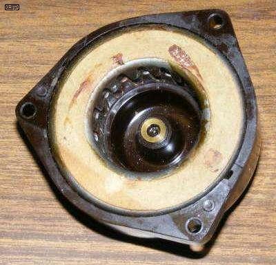
Figure 11 - Smith Electric Motor (Rotor Removed)
The motor gets much of its power from the stronger than normal magnets in the rotor. Below, you can see the terminal housing on the back of the motor Bakelite moulding. All that's inside is a couple of screw terminals. There is no provision for a cord anchor of any type, and there's no earth terminal (nor anything that looks like one) on the movement itself.
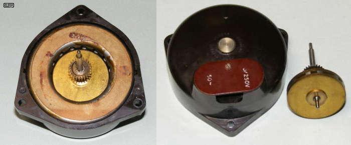
Figure 12 - Motor, Rear of Housing and Rotor
The 'motor' itself is only the coil, magnetic pole-pieces and terminals, and it was very obvious when taking it apart that doing so was never expected. Should the coil fail, the entire Bakelite coil housing would have been replaced. The mains cable is terminated by the screw terminals, and no form of cable strain relief exists (or ever existed as near as I can tell) anywhere inside the case. All in all, this arrangement is decidedly unsafe and should not be used in its original condition. This is fine, because it is now operating from 16V AC. Before disassembly, the measurements taken from the motor's stator (the part with the coil) are as follows ...
Measured Supply 240V AC Minimum Voltage 160V (motor just runs) Current 16.4 mA DC Resistance 5.8k Ohms VA Rating 3.94 VA Power Dissipation 1.56W
This looks like it should be fine with around 800 turns, and although a proper test should have been run using the method described for the Telechron motor, I didn't. This motor is sufficiently different from the previous two that assumptions should be avoided, but I've been doing things like this for many years, so elected to just rewind the coil using the 'educated guess' method. Because of the different construction, the new coil former would have needed to be made first, because it's not possible to wind turns directly onto any part of the magnetic circuit.
This former would also have needed to be reasonably robust because of its large internal diameter. In this case, I decided it was alright to reuse the original former. Because none of the coil is visible (even with the motor coil assembly removed) the appearance of the clock motor remains unchanged. The problem with doing so is that it's extremely difficult to go back if a problem is found. This would require rewinding the motor to match the original coil in every detail (wire diameter, number of turns, etc.). As it transpired, I ignored all my own advice and decided to reuse the original former and just wind as many turns as would fit onto it. I ended up with 700 turns of 0.315mm wire, which worked out perfectly. The new motor's measurements ...
Minimum Voltage 13V (motor just runs) Current 280 mA DC Resistance 21.1 Ohms VA Rating 4.48 VA Power Dissipation 1.65W
As with the previous two examples, this is a good result overall, and the clock is now running (and striking) happily, with its nice new safe 16V motor. The power dissipation is slightly higher than the original, but the motor barely gets warm.
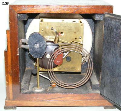
Figure 13 - Rear of Clock After Reassembly
Now that the bulky mains lead is gone, it's much easier to get to the time-setting knob, and also easy to route the cable away from the gong. Because only low voltage is used, there is no need for thick insulation, so the wiring is more easily concealed - or at least kept out of the way.
The final motor here is from a SEC (Smith Electric Clocks) Bakelite enclosed motor unit. In this case, all I have is the back section. There is no dial, hands or bezel. In their defence, the Smith clocks usually isolated all the internals from the outside world, using screws with Bakelite heads to ensure that there was no possible contact with the movement. By today's standards it would be classified as double-insulated, although none that I've seen would pass the modern tests.
Of particular concern is the mains input connector, which is visible in Figure 14. This connector would not pass any modern test, and with good reason. If the connector is partly withdrawn, the live pins on the back of the clock are easily accessible to small fingers or a piece of metal (such as a paper clip). Since the line socket is no longer obtainable if missing, there is simply no safe way to connect mains to the clock. Even if the connector is present, it is too unsafe to use with mains voltages.
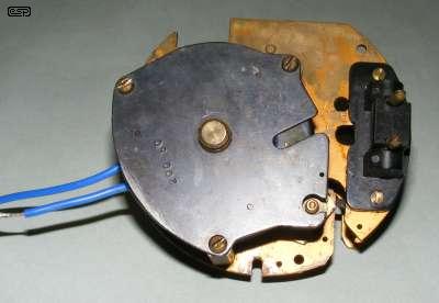
Figure 14 - SEC Motor (Note 'Mains' Connector)
The mains connector has pins that are bare right to the end, and are only 7.13mm long and about 3.7mm diameter. The connector itself is designed to swivel, and all in all it is a very dodgy arrangement. The motor has been dismantled, and the tails of the test winding are seen sticking out of the motor housing. The test winding used is actually only 9 turns, but it doesn't matter as long as you know how many there are.
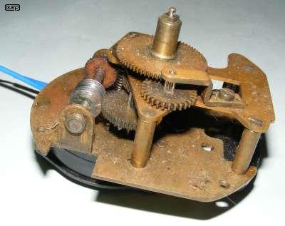
Figure 15 - SEC Movement
As you can see, the movement is filthy, and what you can't see is that the motion work intermediate wheel has a broken pivot. I chose not to clean (or repair) it before the test because I wanted to find out if it could be made to run in its present condition. Of far greater concern than the gunge all over the movement is the condition of the motor coil. As you can see from the photo below, the insulation is literally falling off the coil, there are damaged windings where something has poked into the opening, and there is also a length of uninsulated wire in serious danger of creating a shorted turn (the wire is visible, but the potential shorted turn is around the back).
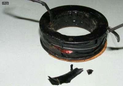
Figure 16 - Smith Electric Motor Coil
There is some of the insulation that fell off shown in the photo. I would never use this clock connected to the 230V mains - it's far too dangerous. Even replacing the insulation wouldn't make me any happier. The only option is a rewind, and low voltage operation is the most sensible.
The test winding shows that the motor will run quite happily with a voltage of about 180mV across the 9 turn winding. Current was also measured, and was a bit over 2 Amps. As noted above in the 'alternative method', the winding gives me a value of 9 turns / 0.18V = 50 turns per volt. To allow for losses, I would want the clock to run with 12V, so 12 × 50 = 600 turns will be needed.
Since the coil size and motor construction is almost exactly the same as the art deco Smith clock shown above, I already know that I can fit about 700 turns into the available winding space. The overall performance will be pretty much identical to the previous example.
This motor has not been rewound - and it may not be, as it is a great example for demonstration to the attendees of the 'Electric Horology Short Course' that was run for NAWCC Chapter 72 during 2008. Since it seems probable that the course will run again, I need demonstration motors.
Given that so many of these clocks have worked as originally built for so long, it may seem odd to suggest that there is a safety problem. Based on the three clocks I've done so far and the additional one tested, the Telechron is probably the only one I'd trust at all (due to it having been varnish impregnated), but there are still serious concerns. There are many ways that insulation can fail, with a nearby lightning strike being a favourite. The instantaneous spike (or surge if you prefer) can reach thousands of volts, and spikes kill computers, TVs, DVD players and other mains powered gear on a regular basis. To imagine that antique insulation can withstand such abuse forever is wishful thinking. Most motors were not impregnated, and the two Smiths in particular had extremely small clearances between live conductors and the clock movement. I wouldn't trust either of them as far as I can kick a piano.
Overall, the process described is a simple and safe way to operate an old synchronous clock. While there are other alternatives to the method described, they require the acquisition of parts that are considerably more expensive than the double insulated 16V plug-pack, and do not offer the same overall safety level.
One such alternative is to use a 1:1 isolation transformer. This removes the earth connection to the neutral, so both AC lines float. If one were to make contact with either one, there is no risk of electric shock. However, 1:1 isolation transformers are not readily available, and if you can get one it will be expensive. There is still a real risk of electric shock, because the output is at normal mains potential, so if you contact both leads at once you will still receive a (possibly fatal) shock. There is no difference between the full output of an isolation transformer and normal mains, except that there is no longer a specific active (live) and neutral conductor.
Because of this, if a number of clocks are connected to the same transformer and one develops a fault, a lethal condition can still be created. For these reasons, I dislike the idea of using mains isolation transformers except under very specific conditions. They tend to create an air of complacency, and that mixed with mains voltage is always a very bad combination. Also, consider that an isolation transformer disables the earth-leakage safety switch in your switchboard, so you (or your loved ones) can die without the mains ever being disconnected.
In addition, using a 1:1 isolation transformer will usually still entail using a normal mains plug on the clock lead, and there is nothing to prevent someone else plugging the clock directly into a normal mains outlet. There aren't too many plugs and sockets available that are rated for (or are suitable) for mains connections, and the standard plug for your locality is the only one that is both readily available and safe to use. Should someone else be unaware of the existence or need for the isolation transformer, any safety advantage is instantly lost. Should the clock change hands a couple of times, it is almost guaranteed that the transformer will not be used at some point - it will be lost or discarded as 'not necessary'.
With a low voltage circuit, any readily available low voltage connector can be used, it doesn't need heavy duty insulation, and needs only to be sufficiently different from the connectors used on other low voltage appliances to ensure they can't be inadvertently interchanged. I highly recommend permanently labelling the end of the lead to identify the correct power source. You may not want to stick a label on the clock itself, as many label adhesives can mar the finish.
A 16V plug-pack as suggested will easily power a number of clocks. The one shown in Figure 1 is rated at 1.5A, so can power four clocks with similar characteristics to those described above and remain well within its ratings. Because the voltage used is (to quote the regulatory verbiage) 'inherently safe', there is very little risk at all. The clock can be safely worked on while out of its case and running, and accidental contact with the supply terminals will not even be noticed (even both at once).
There is a down-side. Because we now have an external transformer, the power usage is increased slightly. In the current climate where everyone is urging us to be more energy efficient, this may seem to be a backwards step. However, the additional power is roughly equivalent to leaving a 100W light burning for perhaps 2-3 minutes extra each day, and is dramatically less than most other appliances with a standby function. In the greater scheme of things, the small amount of additional power used is more than offset by peace of mind and the added safety. Where safety is concerned, I'd much rather an appliance 'waste' a few Watts than be waiting to kill me.
As a side benefit, it now becomes possible to make a simple, cheap inverter power supply that can make 60Hz clocks usable in 50Hz countries and vice versa. This is based on a frequency multiplier, and I have devised a method to maintain complete synchronism with the mains frequency to retain the inherent accuracy. This is followed by a simple low frequency power amplifier. Because there is no requirement for high voltages, the whole project is easy to build, involves no risk of electric shock and will need no expensive (or hard to get) parts. The most expensive item will be the 16V AC plug-pack power supply.
Details of this circuit have been published - please see the clocks index page for the link (it's not for the faint-hearted though).
Clocks Index
Main Index