

|
| Elliott Sound Products | Build a 1 Second Timebase |
 Clocks Index
 Main Index
A timebase is simply a reference system, in the case shown here, providing pulses at a 1 second repeat rate. While a quartz clock is not as accurate as a 'RTC' (real-time clock) as used with Arduino boards and the like, it's more than good enough for most applications (including driving slave clocks). There are many reasons that one might want a timebase, and it could be as simple as providing a means to drive a slave dial, or any number of other applications in horology or elsewhere. Some of the requests I've seen on newsgroups seem very odd indeed, but there's usually a good reason for the poster to want whatever it is that's asked for. I freely admit that this is not an original idea, but it has been extended to cover real world applications - something that another project I've seen fails to achieve in a few areas.
While it's easy enough to use a mains synchronous circuit (see the synchronous clock project in the clock section of my site), there is rather a lot of messing about. While many who have read my articles will know that I don't consider (cheap) quartz clocks to be especially accurate, they are still pretty good if a small error can be tolerated. The best part is that it is so easy to make a simple timebase, because almost everything is already done.
Quartz clocks are cheap - insanely so in fact. As most people have discovered, they are fairly accurate, but can be expected to drift a few seconds each week, and sometimes a lot more. Compared to most mechanical clocks, they are very good timekeepers, but are fundamentally useless as a reference time standard. Be that as it may, even the most average quartz clock is surprisingly good, and a simple timebase is easy to make using the board pinched from a quartz clock movement.
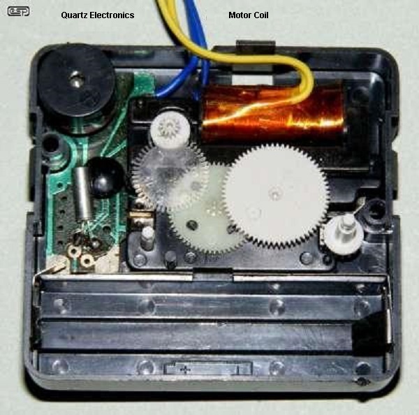
Figure 1 - Quartz Clock Movement
The movement shown above had been modified to bring out the coil leads and PCB coil connections. This was used for demonstrations, but has been sacrificed in the interests of this article. I can always put it back together, but it almost certainly won't happen. The buzzer has since been removed, along with all wiring. Most clock movements are similar, but at times it can be hard to track down which is positive and negative on the board. It's usually visible, but not always. It is important that you get this right, although most ICs will tolerate reverse polarity at 1.5V without damage. Best not to risk it though.
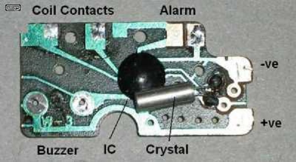
Figure 2 - Quartz Clock Printed Circuit Board
Here we see the printed circuit board after removal from the clock mechanism shown in Figure 1. The board shown has the extra bells and whistles as described, but we ignore these. The connections for the buzzer and alarm contacts are left unused. For most common movements, these extras won't be present anyway. The above photo is an example - there are countless different layouts, but two sets of connections will always be present ... 1.5V DC and the motor coil. These are best traced out as you dismantle the movement, as there are many variations.
When dismantling, be careful not to flex the board. The epoxy covering the IC itself can crack, and this may allow moisture inside the IC which will almost certainly destroy it. If anything need to be desoldered, use a temperature controlled soldering station and work quickly so the IC and PCB is not overheated. These boards are cheaply made and most are easily damaged by heat.
If we look at either of the clock coil terminals (referred to the negative terminal of the 1.5V cell), we see one positive pulse every 2 seconds. If the two are combined, we get one pulse every second. The trick is not only to combine the two pulses, but to raise their amplitude to something useful. In terms of 99.9% of older clock systems, 1.5V at a couple of milliamps is useless. No fancy ICs are needed here - we can easily obtain pulses of 12V or more at several hundred milliamps if necessary. The only thing we can't do easily is make the pulses longer - it can be done, but requires additional circuitry.
One would normally expect that the outputs would be combined using diodes. While this is trivial (and it does work), you lose close to half the available output voltage because of the diode's forward voltage. Alternative diodes can be used (Schottky or germanium for example), but they aren't necessary. By far the easiest way to combine the outputs is shown in Figure 4 - a pair of resistors driving the base of a transistor. The first transistor (Q1) combines the pulses and provides a level-shifting function, converting the 1.5V clock outputs to whatever voltage you need (12V in this instance). The supply voltage is shown as 12V, but can range from 3.3V to about 30V without modification.
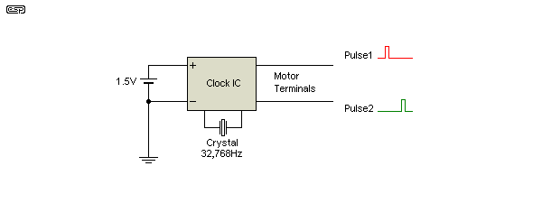
Figure 3 - Pulse Generation From The Clock PCB
Above, we see the separate pulses that the clock IC generates, referred to the negative of the 1.5V supply to the clock electronics. Each pulse output produces one pulse every 2 seconds, with a pulse duration of about 50ms (although this can vary). 'B' is delayed by one second, so that when the two are combined, the result is one pulse every second. Should you happen to require two second impulses, simply don't connect one of the coil terminals (it doesn't matter which). It may not be immediately apparent how this arrangement provides an alternating (true AC) signal to the motor, but consider that when both signals are low, there is no voltage across the motor coil. When Pulse1 goes high, one end of the coil is positive, and the other remains at zero. When Pulse2 is high, the opposite end of the coil is positive. The result is true AC with current flow alternating in the coil once every second.
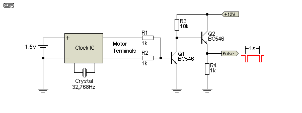
Figure 4 - Basic Pulse Combination Circuit
There is no doubt that the scheme above will work, and it gives clean pulses to the full supply voltage. It also is inverting, so the signal 'rests' at the supply voltage, and pulses to close to zero volts. There are a few places where this might be needed, and by adding an optional emitter follower as shown (Q2 and R4) the circuit can pulse a reasonable current - although it's still only a few milliamps. A general-purpose booster is shown later that can be used with either pulse polarity, and can drive a significant current.
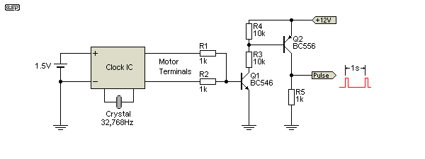
Figure 5 - Non-Inverting Pulse Combination Circuit
In contrast, the Figure 5 circuit is non inverting, so the voltage is normally at zero, and pulses high (to your designated voltage) once a second. Like the Figure 4 version, this is not designed for high current, but it will happily drive pretty much any following electronic circuit.
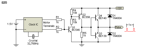
Figure 6 - High Current Output Stage
Both versions of the circuit have limited output current, so where you really do need 100 or 200mA (or more) output current, the addition of Q3 and Q4 as shown will do the job nicely. The extra transistors can be used with either the Figure 4 or Figure 5 circuits. As with the other circuitry shown, the high current output will work at up to 30V or so. More is possible (up to 60V with the transistor types shown), but resistor values would need to be changed to prevent excessive power dissipation.
You need to determine the final requirements for the application before continuing. There's not much point building a complete system that gives 5V pulses at 10mA if you really need 48V pulses at 500mA. You also need to decide how good to make the 1.25V supply for the quartz clock IC. While many of these will operate over a fairly wide range, some won't, and timekeeping will suffer if the voltage isn't stable. It has been claimed elsewhere that some new 'quartz' clocks use something called a ceramic resonator instead of a crystal, and these have much worse accuracy and are affected by temperature. I've not come across a clock using one so can't comment either way, but if you don't see the familiar crystal in its aluminium can with two leads, don't use the clock.
It is possible to use a LED or 2 diodes in series to make a very simple regulator, but both have marginal thermal stability and the voltage with a LED is too high (typically about 1.8V). It won't hurt the clock IC, but it may cause timekeeping to be rather poor. Adjustable 3-terminal regulators are complete overkill for this application, but they are reasonably priced and have excellent performance. Despite the overkill, this is the best way to power the circuit, and in the end it adds little to the cost.
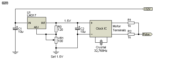
Figure 7 - High Stability 1.5V Regulator Circuit
As a side benefit, this power supply will happily run any number of quartz clocks (perhaps 100 or more), although I must confess that this probably isn't an advantage. VR1 is adjustable to enable the voltage to be set to exactly 1.5V. There is always some variation in the regulator itself, and it becomes significant at very low voltages. The output voltage will be extremely stable - far more so than a 1.5V cell over its normal lifetime. The 10uF caps are not optional - they must be used, and mounted as close to the regulator IC as possible. Without them, the regulator IC will almost certainly oscillate.
The only reason for making the supply adjustable is that in some cases (but not all), a small adjustment might improve long-term accuracy. This is not guaranteed and is extremely hard to test without waiting a long time for a result.
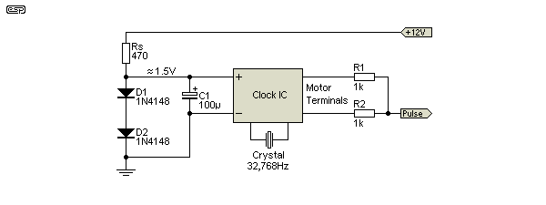
Figure 8 - Budget 1.4V Regulator Circuit
If you are on a tight budget or just don't want to go to the bother of assembling a regulator, you can use the above scheme instead. The voltage is not as stable or accurate as that from an LM317 regulator, but that may not matter to you, and it almost certainly doesn't matter to the clock IC. The two diodes act as a voltage 'clamp' and will keep the voltage to around 1.5 volts with the diodes shown. Current through the source resistor (Rs) is about 22mA with a 12V supply. This is more than enough to power the clock electronics, but the inclusion of C1 (100uF 6.3V) is required to ensure that the supply has a source impedance that's at least as low as a 1.5V dry cell.
If your supply voltage is not 12V you'll need to re-calculate the value of the source resistor to maintain between 15 and 25mA through D1 and D2. This isn't difficult, and uses Ohm's law. The formulae you need are shown below. You need to calculate the resistor value and determine the power rating needed. V is voltage, I is current and P is power dissipation.
R = V / I where V is total supply voltage less 1.4V R = 10.6 / 22 = 0.481 k use 470 ohms
P = V² / R P = 10.6² / 470 = 239mW use 0.5W
The above will work for any supply voltage you may want to use. For example, if the supply is 24V, the resistor will be 1k and needs to be 1W because dissipation is about 510mW. Always use a resistor with a rated dissipation that's at least as high as the calculated power. Using an undersized resistor will lead to overheating and early failure.
As noted, the 50ms pulse from a typical quartz clock IC will be insufficient for many older electromechanical movements. For these, the pulse needs to be 'stretched', or made longer. There are some very simple methods to do this, but their time delay may not be sufficiently reliable, and/or they will be unable to supply enough current. The 555 timer has been the IC of choice for many years, and they are readily available and cheap. While they can deliver ±200mA in theory, this is at the expense of output level. They also get very temperamental if any inductive back-EMF from solenoids get to the output pin, so adding a two transistor buffer is a great help.
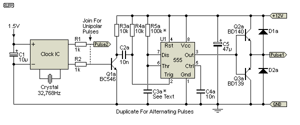
Figure 9 - Pulse Stretcher Circuit
The circuit is shown above. Simply join the two resistors (R1, R2) as shown if you only need a unipolar pulse, or duplicate the entire circuit from Q1a onwards for bipolar (alternating) pulses. When used with two of these circuits (bipolar pulse), the clock impulse motor connects between the outputs of each pulse-stretcher circuit. Only one limiting resistor is required (see below for how to calculate its value).
The two diodes shown (D1 and D2) should be 1N4004 or similar 1A diodes. You don't need to duplicate C5, but doing so won't hurt anything and is actually preferred. The pulse time is set by R5 (a and b) and C3 (a and b), as follows ...
t = 1.1 × R5 × C3 t = 1.1 × 100k × 1µF = 110ms
If you know the optimum pulse width, you can work the formula backwards ...
C3 = t / ( 1.1 × R5 ) ... or ...
R5 = t / ( 1.1 × C3 )
With most electromechanical clocks, it's probably better to err on the high side, so if it's claimed that the movement needs 200ms, allow for 250-300ms. This won't hurt anything, but ensures that current is available for long enough to ensure that the movement advances. If two 555 circuits are used, make sure they are set to the same time period. There will always be some variation, but they do need to be fairly close. C3 should not be an electrolytic capacitor - use a film type, as they are much more predictable. R5 should not be greater than perhaps 220k - the 555 datasheet says that even as high as 1MΩ is alright, but I would not use such a high value.
If your clock needs more than 12V to operate, you will need to use one of the schemes shown above to increase the output voltage. The 555 timer is limited to 18V (absolute maximum), so you should not operate it at more than 15V or so, or it will die. In some cases, a clock may be designed for a specific current rather than voltage, so you may need to add a resistor in series with the pulse output to set the required current.
A movement that expects 200mA (for example) may have a resistance of 25 ohms, so with a 12V supply, you'll need to calculate the resistance needed in series with the output.
I = 200mA, R = 25 ohms, V = 12V R = V / I R = 12 / 200m = 60 ohms (total circuit resistance) Rx = 60 - 25 = 35 ohms (use 33 ohms) (Where Rx is the external resistance required) P = I² × R = 200m² × 33 = 1.35W (use 2 watts)
Now you can substitute your own values and measurements, and work out what you need for the movement you have. To most people experienced in electronics, this is fairly trivial, but it's certainly not trivial for someone who may know a lot about clocks, but little about electronics. Unfortunately, it's very difficult to make this any simpler, because it's already simplified about as far as is possible. The only really simple way to do it would be to buy what you need, but since no-one makes this kind of circuit (at least none that I'm aware of), you don't really have a choice.
The techniques shown here all work well, and hopefully will help anyone needing a reasonably accurate 1 second timebase. As noted above, if you need a 2 second timebase, simply disconnect one of the clock motor leads. The only limitation is the relatively short pulse provided by the clock electronics. At around 50ms (0.05s) it's more than acceptable for any electronics, but is probably too short to drive a relay or a 'full sized' clock or slave that relies on an electrical impulse. If this is the case, use the circuit shown above, as that can be worked out for almost any pulse width likely to be needed.
The circuits are not restricted to clocks by any means. Any application where a fairly accurate 1 second timebase is needed can use this arrangement. It is highly doubtful that you'll find anything that gives the accuracy of the methods shown here for anything like the cost (which really is peanuts). Needless to say, you can delve into TCXOs (temperature controlled crystal oscillators), crystal ovens, GPS receivers etc. if you need extreme accuracy. For most applications these techniques will not be needed, and for most people's needs one of the circuits shown here should be just the thing.
 Clocks Index
 Main Index