|
|
| Elliott Sound Products | Turntable Drive Systems |
Turntable Drive Systems
Rod Elliott, © 2025
 Main Index
Articles Index Main Index
Articles Index
|
When you look at reviews of turntable motors and drivers, you will see some remarkable tales of how this motor and that power supply will transform your listening experience. This is generally 100% unadulterated bullshit, and there are some well known sites that engage in nothing but. As always, I take a pragmatic approach, and describe the differences in operation. It's up to you to decide whether it influences the sound (there are some designs that must have an influence, but it's mainly related to low-frequency noise).
Reading about how a DC motor gave greater delicacy to cymbals and that a bigger transformer made an AC motor provide greater weight to the bass region would have made me laugh if I wasn't so busy muttering to myself that the writer was obviously either on heavy 'self-medication' or had failed to take a required prescribed medication to ease his symptoms of self-delusion.
The above notwithstanding, there are things that motors can provide, mostly not good. Rumble, bearing noise or unstable speed are examples, but if a motor is in good order, it only needs a power supply to do what it has to do. And what is that? Spin the turntable at the correct speed - 33⅓ or 45 RPM (or occasionally 78 RPM). For the latter, accurate speed isn't so important, because the early shellac pressings rarely had the right speed anyway, as they were intended for wind-up (spring driven) motors. Speed was determined by the setting of the mechanical governor, and almost no one ever checked or adjusted that.
Fully electronic motor drivers are fairly common, but most are surprisingly expensive, and doubly so if they are endorsed by various audiophool websites. The circuits discussed here are designed for motors that draw up to 10VA or so, a current (at 230V) of around 45mA. The drive frequency is critical, because it needs to be stable and if you need to change speeds on a TT that is designed to operate at a single speed, the frequency needs to be easily switchable.
One design shown here is designed for small, synchronous AC motors, a common motor used in many belt-drive turntables. They are low-torque and can take some time to get a heavy platter up to speed, but once they have reached their synchronous speed they are as stable as the oscillator driving them. Many are designed for direct mains operation (50 or 60Hz) and they are not interchangeable because the pulley has to be the right diameter for the platter to get the right speed. A 50Hz motor will run 20% fast if used with 60Hz mains, and a 60Hz motor will run 16.7% slow with 50Hz mains.
A considerable resurgence of vinyl in recent years has meant that more people are interested in buying or restoring old turntables. This process can range from being dead easy (simply replacing the belt for example) to very difficult, if the motor has failed or the electronics that control it have died. Most of the older electronics can be repaired easily enough, but as always, there will be people who want to 'upgrade' the electronics for one reason or another. There's also the problem of mains motors designed for one frequency (50 or 60Hz) to be used where the frequency is different. This can cause a real headache, especially for old turntables for which there are no spare parts available (such as motor pulleys or even belts in some cases).
There are many turntables that use a more-or-less conventional synchronous motor to drive the platter using a belt and pulley. Some use a stepped pulley for different speeds, some use an oscillator with different frequencies (and voltages) for the speeds offered. Most provide 33⅓ (33.33) RPM and 45 RPM, with a smaller number offering 78 RPM as well. Many such systems provide a 'vernier' control for fine pitch adjustment, which may or may not offer enough range to cater for 78 RPM discs. When these were cut, the speed wasn't always well controlled, and it can vary over a fairly wide range with some early recordings.
To complicate the issue, some motors operate from mains voltage and frequency, and generally have different sized motor pulleys to correct for the difference between 50Hz and 60Hz mains frequencies. Others are driven from low voltage, typically around 6-12V RMS (although this can vary depending on the design). Mains powered motors use a capacitor to provide phase shift to one winding to ensure that the motor is able to start, and does so in the right direction. Low voltage motors often use a quadrature oscillator (two sinewaves, one sine, the other cosine), with the outputs displaced by 90°.
There are also direct drive motors, and while they operate on essentially the same basic principle, their speed is the same as that of the platter. No attempt will be made to cover these in great detail, as the drive systems are proprietary, and no two different brands use the same drive system. There are many people who dislike direct drive, and just as many who love it. This is not an argument that will be entered into here.
You'll find endless discussions (and just as many arguments) about the construction. Some makers prefer a very heavy platter (where the vinyl disc sits) with equally massive chassis components, while others use a light platter (and chassis) made from more mundane materials, such as MDF (medium density fibreboard) or one of many plastic materials. You'll find glass, aluminium, brass (with or without tungsten inserts to add mass), and in some cases, composites of different materials. Steel cannot be used because it would interfere with the operation of the magnetic pickup cartridge. Every maker will claim that their method is superior in some way, and it stands to reason that they can't all be right. One always has to try to separate engineering from marketing, but the lines can be very blurred in many cases.
The same applies to motors, belts, drive electronics and anything else that can be used to differentiate one product from 'the rest'. This article only discusses motors and drive systems, and does not even attempt to delve into the even muddier waters that surround tonearms and pickup cartridges. Even finding consensus on platters and motors is hard enough - the other parts of the system are even less clear-cut. In general, most of the popular brands/ models will be perfectly alright for most listeners, but if you want something more 'exotic' you need to do some homework before you commit.
Excluded from this article is any description of 'clockwork' (i.e. spring drive) motors, as they are irrelevant to any discussion of high fidelity systems. They may have been the only viable option over 100 years ago, but it's highly doubtful that you could even get a new one now.
There are several different approaches to motor drive as indicated above. These will each be covered below in a bit more detail. The speed accuracy should be as good as possible, but there's no point expecting it to be perfect, because there are limitations that affect all drive systems. Few people have 'perfect pitch', so absolute accuracy is generally less critical than stability. For example, the speed shouldn't change when the cartridge stylus is in the groove of a record, and nor should it change because the stylus is playing an outer groove (higher loading) vs. an inner groove (lower loading).
Synchronous motors will retain their speed regardless of typical loading of the stylus, but stability can vary if the applied frequency changes. If the change is small, slow and irregular (no repetition) it's likely to go un-noticed. A heavy platter minimises short-term speed variations that may result from motor vibrations or loading that causes the drive-belt to momentarily change its tension (albeit very slightly). A light platter allows the system to come up to speed quickly, unless a very powerful motor is employed.
If the disc's centre hole is not exact, you may hear a regular 'warble' (generally called 'wow') on sustained notes, but no drive system should ever deviate at a regular rate such as to be audible. Opinions vary widely as to the audibility of small changes or the speed accuracy, and again, these arguments will not be covered here. It's probable that if the speed is within 0.2% and the frequency change over time remains within the same limit, most listeners be unable to hear it. For 33⅓ RPM discs, this would mean that the platter variation would remain within 33.27 RPM and 33.40 RPM, but with no short-term variations.
Of course, all of this assumes that the original recording was made with tape machines that run at the exact speed of the tape machine used to play the recording when the disc was cut, and that the cutting lathe's motor speed was also exact. This isn't something that is guaranteed, and the information is not disclosed. There is (apparently) a test disc that has been used for verifying turntable speed that was cut slightly slow, so users report that their turntable is running a little fast. I don't have any evidence one way or another on this, but it's something that needs to be considered before you condemn your turntable as 'inaccurate'.
There are further variations in drive systems. Belt drive is often considered to be the 'best' by many people, and most 'audiophile' turntables use this system. It has the advantage that motor vibrations are isolated from the platter, due to the resilience of the belt. Of course, belts don't last forever so you must expect to replace them every so often. Some systems have the motor (and associated electronics if applicable) in a completely separate box, with no connection to the main turntable plinth other than the belt. If the motor unit is moved even very slightly, the belt tension will change, which may cause slippage or excessive belt tension. I expect that this could be annoying - especially if one has small children in the house. Otherwise, it does ensure the best possible isolation once it's set up properly (assuming that the platter and its plinth have good isolation of course).
The exact positioning of the motor depends on the manufacturer, and in some cases it won't be attached to the turntable plinth at all. Instead, it's mounted next to the plinth, and is usually weighted to ensure that it stays where it's placed. This is an extreme case, and the vast majority of belt drive turntables use a resilient mounting for the motor to prevent mechanical noise being transferred to the turntable via the plinth. Note the flat belt motor pulley - the 'barrel' shape keeps the belt centred over the widest section of the pulley. This may be counter-intuitive, but the same 'trick' is used for belt sanding machines and was standard when factories used flat belts to power everything from a central steam engine.
Some belt drive 'tables use dual pulleys as shown above, with a mechanical lever to shift the belt from one to the other. With some, this is done manually, with no mechanism at all. Others use an electronically driven motor, so speed change is done by changing the frequency of the AC delivered to the motor.
The motor is always located as far from the pickup as possible, because that minimises the hum pickup from the AC fields created by the motor (including DC motors). In many cases, the motor will also have a magnetic shield, using mu-metal (ideal but expensive) or grain oriented silicon steel (much the same as that used for transformers). The relative diameters of the motor and turntable pulleys determine the motor speed needed for 33⅓ and 45 RPM. There may be a small 'fudge factor' due to the belt thickness, because that can influence the effective diameter of the motor pulley (in particular).
Opinions vary as to the 'ideal' material for both the platter (and associated mat) and the plinth. An inert, non-resonant material is preferred, although machined cast aluminium is very common for the platter, with any tendency to 'ring' (resonate) damped by the mat and/ or additional damping material. The plinth is often wood (plywood, MDF [medium density fibreboard] or natural timber), but budget (and some no-so-budget) plinths may be made from injection moulded-plastic or acrylic. Concrete and stone are less common, but add weight, 'substance' and cost to the plinth. Ideally, the entire turntable will be isolated from the shelf/ bench it sits on, to minimise low-frequency feedback through the floor and reduce the tendency for the stylus to 'skip' as you walk around (a requirement for suspended timber floors).
With early turntables, idler-wheel drive used to be common, especially for record changers which needed considerable power from the motor to operate the changing mechanism. These are not considered 'acceptable' these days, and I haven't seen a new version offered by anyone. These were used in some turntables that enjoyed a fairly good reputation in the early 1970s (e.g. Elac, Dual) and used a synchronous PAPST 'outer-rotor-motor', where the rotor was on the outside of the motor windings. Such rotors were generally quite heavy, and acted as a good flywheel, minimising rumble. Being synchronous, they remained as steady as the mains frequency. Like all synchronous motors, when turned on they behaved like an induction motor until the magnets locked onto the mains frequency. A later variation of this style of motor is common for model aircraft, and is often called an 'outrunner'.
Many people now avoid even automatic arm return when the disc's run-out grooves are reached, and (if available) some modern examples use a separate motor for this function. The alternative is to simply switch off the motor so the stylus doesn't sit in the spinning run-out groove forever. This generally uses a very low drag mechanical switch.
The final system is direct drive, where the motor supports the platter and runs at the same speed. These are always electronically controlled, either using fairly basic analogue electronics (common in early designs) through to crystal-locked systems of considerable electronic complexity. Direct drive is generally favoured by DJs, as the disc can come up to full speed in less than one full rotation. When first introduced, direct drive was hailed by the manufacturers as the best system available, but there were (and still are) people who claim that it's inferior to belt drive. Most of the 'complaints' seem to be purely subjective, and little evidence is available to support the theory.
In short, there is no system that's 'best'. User preferences, the type of disc (vinyl, shellac) and whether or not automatic record-changing is required (very uncommon these days). Many people (me included) use a direct-drive turntable, but others will claim that these are grossly inferior to belt drive. In general, this is probably not the case, and the quality of some vinyl records may be such that you'd be hard-pressed to pick the difference between a 'proper' hi-fi unit and a budget buy from a department store.
Note that this article discusses drive systems only. There's nothing here about tone arms or cartridges, as they are a separate entity. Quite obviously both will affect the sound (along with the RIAA preamp), but they are divorced from the platter and motor, even to the point where some turntables are supplied without either - it's up to the buyer to purchase the tone-arm and cartridge separately, and attach them to the turntable plinth as desired.
These motors are (or were) very common, and there have been many variations. PAPST motors are/ were different (these are also known as 'outer rotor motors') and many only have a single winding (referred to as a 'hysteresis motor'), while others use a capacitor as shown in Figure 1. Many German turntables from the 1960s and 70s (e.g. Elac, Dual and several others) used these motors, and they were fairly large and powerful, and easily able to operate a record changer system without stalling. Most used an idler wheel drive system rather than a belt, because belts can have issues driving a changer mechanism. These were never 'audiophile' systems, but many were remarkably good - much better than 'ordinary' record changers built into self contained 'record player' systems. With a heavy platter, 'wow' (slow speed variations) and 'flutter' (high speed variations) were low, provided the idler wheel was in good condition.
Nearly all mains frequency motors use a stepped pulley on the motor shaft to allow speed changes, including idler-wheel rim drive systems. The platter speed is determined by the ratio of the motor pulley and the platter drive ring (whether belt or idler wheel), and for idler wheels the diameter of the idler wheel is irrelevant. This may not seem possible, but the relative ratio between the pulley and idler wheel and the idler wheel and platter cancel out. That leaves only the pulley and drive ring as the controlling factors. Probably a good thing, because the idler wheel is generally slightly soft, so it deforms under pressure.
Belt-drive mains synchronous motors are very similar to the motors used for low voltage drive, but they have many more turns of wire to increase the impedance. They are almost all of very low power, with some taking several seconds to bring the platter up to speed. Because the motors are synchronous, they run at a speed determined by the mains frequency and the number of poles. In turn, this determines the respective size of the motor and platter pulleys. When first started, these motors operate much like a standard induction motor, and once almost up to speed the magnetic poles will 'lock' so the motor runs synchronously, at a speed determined only by the mains frequency. Mains voltage changes have no effect, other than to affect torque.
These motors (almost) always use two windings. A capacitor is used to shift the phase to one motor winding with respect to the other, in theory by 90° but in reality it's always somewhat less. This doesn't matter as long as there is enough phase shift to make the motor turn when power is applied. In general, the mains frequency is stable enough to ensure that the turntable rotates at (very) close to the correct speed, although small variations during the course of a day are quite common. In general, the frequency can be relied upon to be within ±0.2% of the correct value ... most of the time. That greater variations will occur is obvious, but it's unusual for these variations to be audible when listening to your favourite vinyl. Of course, this does not mean that such variations won't be audible with some listeners, and for purists this may be considered unacceptable (whether they can hear it or not).
The above shows the general wiring scheme used with mains synchronous motors. The value of C1 is determined by the characteristics of the motor itself, and varies depending on the motor. The motor can be reversed by swapping the mains input connection from point 'A' to 'B' (using the 'Fwd/ Rev' switch if required), and because these motors use two identical windings C1 doesn't need to be changed in value. Not that there's any real point to reversing the motor in a turntable of course - most pickup cartridges and tonearms would not be happy with the disc spinning backwards. A small number of these motors may include a tertiary winding, in one case I found, this was used to act as a low current transformer to power the RIAA preamp. This is not an idea I'd recommend.
One of the disadvantages of mains powered synchronous motors (with belt drive) is that there is no (easy) way to change the platter speed by a small amount. Some people like to be able to change the speed by up to ±5%, either to synchronise the pitch and/or speed to a musical instrument, or simply because they prefer the recording at a slightly different pitch from that recorded. This can be done, by using a tapered pulley on the motor, but this is vulnerable to mechanical vagaries that make it 'sub-optimal' as a solution. A tapered pulley cannot be used with a belt drive, but some idler-wheel drive systems used this method.
With any AC motor, the synchronous speed is determined by the following formula (the factor of 120 is twice the number of seconds in one minute) ...
RPM = f × 120 / N (Where f is frequency, and N is number of poles)
A 16 pole motor running from 50Hz mains therefore has a synchronous speed of 375 RPM (or 450 RPM with 60Hz mains). Note that the number of motor poles is determined by the way it's wound, and this has no bearing on the number of wires from the motor. As noted, many such motors are 3-wire (one is common to both windings) and others are 4-wire, with these generally being low voltage types. Mains powered synchronous motors have different requirements depending on the voltage and frequency. While the voltage can be increased (or reduced) using a transformer, the frequency cannot be changed. The most common way to provide the correct platter speed(s) is to use different pulley sizes (60Hz motors use a smaller pulley).
For example, a 'spare' turntable I have uses a 4 pole synchronous motor, so it runs at 1500 RPM (50Hz). The platter pulley is 210mm diameter, and the motor pulley has two different diameters for 33⅓ RPM and 45 RPM. Calculation based on the platter pulley and motor speed indicates that for 33⅓ RPM, the pulley needs to be 4.666mm diameter ...
( 33.333 × 210 ) / 4.666 ≅ 1,500 RPM. For 45 RPM, the pulley needs to be 6.3mm diameter.
Note that this calculation does not consider the thickness of the belt, which changes the ratios slightly. For most 'normal' engineering calculations, a small speed error may be of no consequence, but this isn't true for a turntable. The actual diameter of the motor pulley is adjusted so that it's made smaller by (very approximately) half the thickness of the belt. Using the wrong belt may therefore change the speed slightly if its thickness is different from the original. This is far from an exact science, because much depends on the effective thickness of the belt, which is not necessarily a fixed ratio such as half the belt thickness. It's extremely hard to get any real data on this, but you can be sure that the maker of the turntable took it into account. However, no corrections are needed for an electronic control system because the motor speed can simply be adjusted slightly to compensate for any error.
When a flat belt is used, if you look carefully at the motor pulley you'll see that it's slightly barrel shaped, with a small bulge in the middle of the belt's contact area (see Fig. 4.1 for an example). Perhaps unexpectedly, the belt will always migrate to the larger diameter part of the pulley. This doesn't apply to 'string' type drives, which are normally located in a groove on the motor and turntable pulleys. The two belt types are usually not interchangeable. Various materials are used for the string drive, including experimental material such as thin fishing line, dental floss and various types of actual string.
It's important to understand that the distance between the pulleys (and therefore the length of the belt) is irrelevant, provided it's maintained at a constant (and appropriate) tension. If the tension is changed appreciably, the speed will be affected because the belt thickness (or diameter) will change as well, the belt/ string will slip or (for DC motors) the speed controller may not be able to maintain a constant speed if the loading is changed. Excessive tension is something to avoid, as it causes lateral bearing wear (both motor and platter bearings).
Mains synchronous motors can be powered from a low voltage oscillator and power amplifier stage, followed by a step-up transformer to bring the voltage back to 120V or 230V. This is inefficient, because step-up transformers need a fairly high input current for a much lower output current. However, the power requirements are quite low, so the inefficiency is of no real concern. In some cases, the oscillator may be a quadrature type (providing sine and cosine waveforms), followed by two power amplifiers and transformers. This eliminates the need for the motor capacitor.
With any such system, it's important to ensure that the secondary current (with the secondary used as the primary) is below the maximum VA rating for the transformer used. For example, a 12V, 6VA transformer operated in reverse must not draw more than 500mA at any voltage or frequency. Ideally it will be somewhat less. The output voltage will be lower than the nominal mains voltage rating for the primary, because the transformer will always be wound such that the 12V output will be somewhat greater than 12V with no (or light) load. You may expect a 240V:12V transformer to have a turns ratio of 20:1, but it will almost certainly be less (perhaps 17:1). That means that 12V input to the secondary will result in an output of around 204V, not the 240V you expected. One I tested (4VA) drew 170mA with 12V input (184V output), and even with the full 330mA input (at ~14V) the output was only 212V, somewhat shy of the 240V expected. For a detailed explanation of transformers, ratios, ratings, etc., see the Transformers series of articles.
Low voltage systems use a motor that is identical in principle to the small mains operated types, but work with a low voltage AC waveform that's almost always generated electronically. A common scheme uses a fairly conventional quadrature oscillator, and this drives the motor. It's often thought that these offer better frequency stability than mains powered versions, but that's not always the case. Capacitors change value (albeit only slightly in a domestic application) depending on temperature, and other parts (resistors and trimpots) can also drift off value, especially 'vintage' parts.
In some cases, a small AC motor can be almost identical to its mains voltage counterpart, but wound for a lower voltage. This can be supplied from a transformer, and a phase-shifting capacitor is still required (but with a higher value to compensate for the lower impedance windings). This can be an advantage for internationally available motors, with just the pulley needing replacement for the different mains frequencies. Transformers are readily available at relatively low cost, and it would be cheaper to make the motors the same and use a different transformer than vice versa.
Some of the low voltage motors are 4-wire (two separate windings), while others are 3-wire (two windings, with one lead common to both. The drive system can be quite different for the two types, adding to the complexity. There can be no 'one size fits all' approach here because of the differing requirements. Some are 3-phase (with three windings), which (in theory) has a smoother rotation because the motor poles are 120° apart (assuming just 3 poles - there will usually be at least 6, often many more. Direct drive (discussed below) is almost always 3-phase.
A new idea has cropped up of late, where a microcontroller (Arduino or similar) is used to generate the waveforms needed to drive the motor. The signal is then filtered to remove high frequency 'artefacts' and reduce the distortion. Small amplifiers are then used to drive the motor. This approach has the (apparent) advantage of electronic simplicity, and if the µcontroller uses a crystal oscillator the speed accuracy can be very good. However, the micro has to be programmed, and the signal amplitude corrected for frequency.
When the drive frequency to a motor is changed, so too is the amplitude. At higher speeds, more drive voltage is needed to maintain the correct motor current or torque will be reduced. Likewise, if the frequency is reduced, the voltage must also be reduced or the motor will draw too much current and may overheat.
One of the early Thorens (TD125 Mk. 2) low voltage drive systems uses a fairly simple lamp-stabilised Wien bridge oscillator and a phase shift network to produce the 90° phase offset between the two drive waveforms. It uses a total of nine trimpots, used to set the three frequencies and adjust the drive voltage for each of its two outputs. Setup would be rather tedious (to put it mildly). Oddly, the speeds provided are 16⅔, 33⅓ and 45 RPM. The frequencies are not stated in the service manual, but it would appear that for 33⅓ RPM the oscillator frequency would be around 37Hz. I don't have one so I can't verify that. The manual also doesn't provide the DC supply voltages for the oscillator/ amplifier section, but it's probably between ±12V and ±15V to allow sufficient headroom at the highest output voltage.
Note the plethora of trimpots. R14 (5k) is a pitch control, included so that the user can adjust the pitch as needed. R20 & 22 set the oscillator frequency for each speed, and the remaining trimpots set the motor voltage for each speed and phase. Because motor current increases as the speed is reduced, the voltage is changed to maintain constant torque and ensure that the motor doesn't overheat at low speeds. Back when these were made there were few opamps readily available, and µA709C opamps were used. These require external frequency compensation, which is not shown. Somewhat confusingly, they were available in 8, 10 and 14 pin packages, and the Thorens circuit used the 14-pin versions. The original circuit also had provision for 16 RPM (16⅔ RPM), but that's been removed from the drawing.
The oscillator is a Wien bridge type, but only the series leg is changed to vary the frequency, unbalancing the bridge. This causes large voltage variations as the frequency is changed, and the lamp (used to stabilise the amplitude) is unable to maintain a steady level. The frequency isn't shown in the service manual, but at 45 RPM it would (probably) have been about 50Hz. For 33⅓ the frequency would be 37Hz, and 18.5Hz for the [now deleted] 16⅔ RPM (note that the frequencies are approximate). The drive voltage varied from 3.2V at 16⅔ RPM, 5V for 33⅓ RPM and 6V at 45 RPM with both motor drive signals at the same level. The opamp output drives output transistors in 'pure' Class-B, so some crossover distortion would be evident. This will not cause any audible effects. The phase shift is produced by C8 and R7, and only manages a shift of about 45° - less than the optimum 90°, but enough to cause the motor to rotate.
IMO, the choice of phase shifter (capacitor to resistor) was ill-conceived, as it creates distortion because it boosts high frequencies. A resistor-to-capacitor version would have been 'better', but in reality there's probably not a vast difference. A resistor to capacitor phase shifter attenuates high frequencies so reduces distortion. It can also get closer to 90° phase shift.
There are many variations for motor drive systems, some being easy enough to analyse, others much less so. If you plan to 'upgrade' a drive system, then you must know the frequency and voltage required for each speed beforehand, as it may be next to impossible to find out from service manuals (even if they are available). Some low voltage drive systems are almost identical to their mains driven equivalents, except the voltage is lower and the current higher. Although 2-phase systems may use two amplifiers (with the signals 90° apart), others just use a single output with a capacitor to one winding to obtain the phase shift. It needs to be much larger than those used with mains motors, but the principle isn't changed. While there are crystal locked 'low voltage' systems that are truly low voltage, some operate at much higher voltage than you might expect - one I looked at used an 85V motor!
While building a circuit suitable for low voltage synchronous motors is not especially difficult, finding a suitable motor is another matter. They are available, but finding a motor and compatible drive circuit can be challenging. If you know enough about the different motors and how they expect to be driven, it's possible to work out a suitable driver circuit for almost any motor. Re-building original circuitry is one way (if you can get a service manual), but some are overly complex, and others may require parts that are no longer available or very hard to get (6V, 20mA lamps or specialised thermistors for example).
There are some turntables that use a fairly basic DC motor. These were common in cassette decks, and most included a simple 'governor' that relied on a small weight to connect and disconnect the power to keep the motor at the right speed. When the motor slowed a little, the contacts closed for longer, increasing the power to the motor and vice versa. The short-term speed stability of these motors is pretty poor, so they generally used a belt drive to a fairly substantial flywheel that smoothed out the small fluctuations. Longer term changes are also fairly common, and speed stability overall is rather poor. There are also much higher quality DC motor systems available, generally using feedback to maintain the exact motor speed.
Designing a really good speed control system for DC motors is almost an art form. Most high stability systems rely on a tacho-generator of some kind to provide feedback. This can be another motor acting as a generator (which adds considerable load to the motor), or a slotted disc or band with a photo-interrupter that produces a number of pulses for each revolution. Electronic feedback circuitry compares the feedback pulses to a reference frequency, and adjusts the motor power to maintain the desired speed. These can be very accurate, but the electronics involved are complex and can be very hard to make stable.
When done properly, these motors can perform very well, but they have other issues. Because they are conventional DC motors, they have a commutator and brushes. These wear and the motor eventually has to be replaced if it sees a lot of use, and the commutator switching creates electrical noise. Various techniques are used to minimise this, including ferrite beads, capacitors, or even 'full-scale' inductor-capacitor filter circuits.
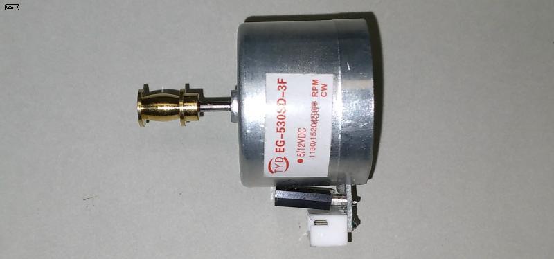
There is a fairly common DC motor with an integrated speed control IC (do a web search for DC vinyl turntable motor). Depending on who writes the material you read, these vary between 'unusable' and 'superb', often for motors that are visually identical. The IC used is an AN6652, which appears to use current feedback to stabilise the motor's speed. This motor sells for anything from US$12 or so, up to US$50 or more, depending on where you get it. If bought from a 'high-end' supplier as a replacement or a spare you'll pay dearly, but visit eBay or AliExpress and you get exactly the same motor for a fraction of the price.
I've run a number of tests on the motor I got (AU$20 near enough), and it seems to be well made and should perform well. The documentation supplied is non-existent though, and the set speed appears to be 450 RPM on the one I bought, but I measured 984 RPM. One thing that is very noticeable is that the motor has very low inertia and shows no sign of 'cogging', where the rotor is attracted to the permanent magnet stator. This seems to indicate that the rotor may be ironless - using specially wound rotor coils that are self-supporting and have no iron core. Well they do, but it's arranged so it doesn't rotate, with the coils between the stationary magnets and inner core. It's very quiet, especially when compared to the next motor I tested.
One way that a motor's speed can be controlled in real time is to use negative impedance drive. This rather bizarre concept is covered fairly thoroughly (see the Negative Impedance article), but motor control is a specialised version. It's suspected (but cannot be confirmed easily) that the AN6652 uses negative impedance control, as without a tachometer there are few other options. I've played with it, and a circuit is shown below. However, this is conceptual, and is not a final circuit. There are many interdependencies that have to be considered, and the circuit needs to be tweaked to suit the motor being used.
I tested this with a modified motor of the type shown below. The governor was disabled and I drove the motor with this circuit. When loaded, it was possible to keep the speed almost perfectly constant for a preset speed, but without a dynamometer I can't really testify as to the accuracy - I just used a basic 'finger test' with a strobe. It looked very good, but it would need much more rigorous testing to be certain that it was stable. Negative impedance is an inherently unstable condition, and it's easy to end up with an oscillator. The negative impedance needs to be adjusted for a given speed for best results.
VR1 sets the speed by simply buffering the pot wiper with U1A. The amount of negative impedance is set using VR2, adjusted so that when a load is applied to the motor, it neither slows down nor speeds up. You will almost always have to put up with a small amount of speed reduction with load, as that's just below the point where overall feedback becomes positive, causing oscillation. With motors, this is often referred to as 'hunting', where the motor is forever trying to achieve the right speed, but overshoots and undershoots continuously.
The principle of negative impedance motor drive is to ensure that when the motor is loaded, the applied voltage increases just enough to ensure that the speed remains substantially constant. A simple circuit such as that shown above is limited, but can still give surprisingly good results. Be aware that if the load is a large motor, the MOSFET will be subjected to considerable power dissipation, but this is a non-issue for driving a turntable.
A practical negative impedance motor drive is shown in Fig. 4.3. The difference is that it can operate with a single supply, which the Fig. 4.2 version will not (I built and tested both versions). I used a fairly powerful motor that has a nominal no-load speed of around 6,000 RPM. With only about 1.6V across the motor it would normally be so feeble that it would pretty much stop if you looked at it the wrong way. With the negative impedance drive I ran it at about 750 RPM, and it was surprisingly stable. As a load is applied, the motor voltage increases to compensate for the load, and the trick is to get enough positive feedback to keep the speed stable, but not so much that the speed becomes unstable. If there's too much positive feedback, the motor will be seen (or heard) hunting - speeding up then slowing down cyclically. The rate is determined by the moving mass of the motor's armature.
Within reasonable limits, there was almost no change as the load increased until my power supply went into current limiting (set for 1A). Overall, it exceeded my expectations, and given that the motor I used was far more powerful than needed for a turntable, I found that vibration was very low. Note that the MOSFET must have a decent heatsink if the motor current is more than ~100mA, and even at 100mA a small heatsink is needed, as the MOSFET can dissipate around 1W with no (or light) loading. The speed and feedback controls are interactive, so it takes some fiddling to get the desired speed and just the right amount of negative impedance.
In general, it's hard to recommend a standard DC motor due to the use of brushes and a commutator, and the possibility of vibration, largely due to cogging. These should not be confused with so-called 'brushless' DC (BLDC) motors, which are actually AC motors, and use electronic switching rather than brushes and commutator. Most people seem to think that the BLDC motor is a category unto itself, but once you understand that it's really an AC motor with (usually external) electronic drive, it's obvious that there is no real difference between a BLDC motor and a synchronous AC motor. Note that asynchronous motors can also be used, but usually not when you require a stable speed. It can still be done by using a tachometer of some kind within a feedback loop, but that adds complexity and it may become unstable under some load conditions.
This isn't to suggest that a high quality (and preferably ironless rotor) DC motor drive should not be used if it does everything you want, but make sure that replacement motors are (and will remain) available, since they usually cannot be repaired when the brushes and/or commutator wear out. If you get one of the ones shown above you will be able to replace it, but getting one with the right speed for your turntable may be a challenge. Ironless motors are usually intended for relatively light duty, because there is no core to act as a heatsink. Sustained overload will cause the winding to overheat, and if bad enough it may disintegrate! They are usually harder to wind as well, increasing the cost.
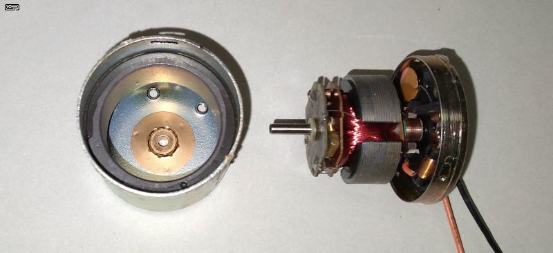
The above photo shows a motor that was common in cassette players, way back when they were still used (yes, I know some people still like them ... for reasons I can't fathom). It's a standard iron rotor, permanent magnet stator, and the governor mechanism can be seen at the far left of the rotor. There are two weights that open contacts when the preset speed is exceeded, in the hope that this will keep the speed stable. It does, but only over a limited range, and it relies on a stable input voltage and a pretty stable load to be able to maintain the preset speed. I measured the speed at 2,760 RPM, which would be a bit fast for a turntable. It's usable though, assuming a turntable of 300mm diameter and a motor pulley of 3.6mm diameter (approximate, not allowing for the belt thickness).
This type of motor has undoubtedly been used for low-end turntables (especially portable types), but hi-fi it most certainly is not. It's mechanically and electrically noisy (although not frighteningly so), neither of which was a real issue with a fairly low-end cassette deck. However, this is otherwise a very well made motor, complete with magnetic shielding (removed for the photo), and is likely at the upper end of the budget motors available at the time. For reasons that escape me, I have box of the bloody things, so sacrificing one was not at all troubling (but I can [and have] put it back together without too much effort). The usefulness of these is dubious, as the shaft is 2.5mm diameter and only 5mm long when assembled.
It worth noting that measuring the speed of small motors is not straightforward. I used two different laser tachometers, but getting a reliable measurement from a small shaft or pulley is no easy feat. I ended up using a hastily fabricated strobe, using an LED, diode and capacitor, driven from my function generator (50Ω output impedance, so enough current was available). With a pulse width of about 200μs I was able to get a perfect view of the motor appearing to be stationary (I used a tape 'tag' for visibility). The AN6652 driven motor appeared stationary with a frequency of 16.4Hz, and the speed stability is impressive. Even light loading with a finger (not exactly scientific) showed no change unless I pressed too hard. The governor motor fared far less well. Its speed varied slightly just sitting on my workbench, drifting up and down seemingly at random (both motors were powered from a 12V regulated supply).
The strobe test was so good that I'll publish a design for an LED strobe shortly. It will have a lot more current though, as I had to turn off my workbench lights to see the motors properly, which was a nuisance (to put it mildly - I was literally in the dark!). The disadvantage of a simple strobe is that you need to measure the frequency to determine the speed, but they are useful nonetheless. Using a strobe to 'stop motion' on an operating machine can be very helpful to track down problems that aren't able to be seen when the machine is stopped. It's more than a speed tester, it can be a diagnostic tool.
These motors are synchronous AC motors, but the differences are in the way the motor is built and the drive electronics used. Most are 'pancake' style motors, being very low profile so they fit underneath the platter. They generally use more poles than 'normal' synchronous motors, because the motor's output shaft drives the platter directly. Therefore, the motor runs at 33⅓ RPM, 45 RPM and/or 78 RPM. Most are provided with a fine speed control, and the electronics are quite complex. Some may introduce a small amount of 'rumble' (low frequency noise) due to their low running speed. When set for a given speed, the drive signals are set for the frequency necessary to achieve the desired speed. For example, if the motor has 6 poles, the drive frequency for 33⅓ RPM will only be 1.667 Hz.
Note that the following circuits assume 50Hz or 60Hz, but in reality a direct-drive motor will operate at a much lower frequency. The actual frequency depends on the number of poles, which is specific to a particular design. Typically, there could be anything from 10 to 30 poles, with one Fisher design claiming 120 poles. When we know the number of poles we can determine the required frequency ...
f = ( RPM × N ) / 120 (Where f is frequency, and N is number of poles)
So, if we have a 12 pole motor and want it to run at 33⅓ RPM, the drive frequency will be 3.333Hz.
The majority of these motors are 'ironless', using only rotating magnets (the rotor) and stationary coils without an iron core (the stator). That means that no form of rotary connection is needed to the coils, improving reliability. The rotor's position is usually sensed by Hall-effect devices, arranged in such a way as to provide precise information on the exact position of the rotor. Without this addition, the switching system has no direct feedback. Being ironless, there is no tendency to create 'cogging' - a phenomenon where the motor tends to 'jump' from one pole to the next, creating vibration. This can be felt easily in most conventional DC motors when the iron rotor is attracted to (or repelled by) a stator magnet. Since there is no belt or pulley system to reduce the speed, these motors operate at a very low frequency
An example of a 3-phase generator circuit is shown above. With the values given, this takes a 50Hz (or 60Hz with a resistor change) sinewave input, and converts it into a 3-phase output. The outputs would typically drive small power amplifiers (or even just a pair of output transistors for each) to drive the motor, depending on the voltage needed to drive it. If the frequency is increased, the output voltage needs to increase too, so the motor draws the same total power. The amplitude of the input signal can be up to ~5V peak (3.5V RMS) with a 12V supply, but the supply can be increased up to +30V if needs be. The circuit is unity gain for all outputs. Note that the value for R8 is a compromise at 5.6k (50Hz) or 4.7k (60Hz), but trying to make it exact is not required.
The circuit can be adapted for any frequency, but if you needed (say) 1.6667 Hz, the value for C2 could become very large. The capacitance needed is reduced if the resistor value for R4 is made greater (the others don't need to be changed). For example, to get a 3-phase output at 1.667Hz, R4 should be increased to 170k (C2 remains at 1μF). Interestingly, the value of R4 predominantly affects the amplitude of Phase-1, but it does alter the phase-shift of Phase-3 as well.
As noted above, the outputs will typically go to small power amplifier stages. These don't need to be 'hi-fi', but they do need to be able to provide the voltage and current demanded by the motor coils. Because they are low frequency only, the design can be greatly simplified. Distortion is pretty much a non-issue, but sharp transitions (e.g. clipping) should be avoided to prevent the generation of high-order harmonics that may become audible.
The digital circuit can be built using CMOS logic, or can be created from a PIC or Arduino. That means it can be crystal-locked, with the option to make it variable to enable manual speed control. The logic requires an input that's 3 times the desired output frequency, and the shift register creates the 3 phases. Each passes through a multiple feedback (MFB) bandpass filter, all identical. These will need very high value resistors and far more capacitance if used at very low frequencies, as you'd expect.
There are several versions of digital 3-phase generators on-line, with some being overly complex and others that may be dubious. Ideally, the outputs will be 'perfect' squarewaves (equal high and low times), but the one shown is not, so there will be a small asymmetry in the output waveform. The simulator measured it as less than 5%, which should not cause any motor stress (particularly saturation). If you wanted to take it the next step you can use a D-Type flip-flop divide-by-two (e.g. 4013) at each of the NOR gate outputs and increase the clock frequency to 300Hz. This ensures perfect symmetry and distortion simulates at less than 0.1%.
The requirement for the filter is a nuisance, but the three of them are identical. It's designed to be 'close enough' to the desired frequency, with unity gain and a Q of 10. R3 can be made variable to allow fine tuning if you wanted to go that far. Note that the opamps require a ±5 to ±15V supply (not shown). I've used standard value resistors throughout, and you can use the MFB Calculator (available from the ESP downloads page) to check or re-tune the filters for other frequencies. While a pulse waveform (sometimes referred to as 'trapezoidal commutation') can be used in many industrial applications, for a turntable motor that would be unwise. Both electrical and mechanical noise will probably be intrusive.
You could also use something like the MC33035, a high performance brushless DC motor controller containing all of the active functions required to implement an open loop, three phase motor control system. They should be available for around US$10.00 each. Be aware that devices like this provide a more-or-less squarewave output, and may not be suitable for a turntable motor. They also expect positional feedback from Hall sensors, so finding a compatible motor might be a challenge.
In later direct drive models, the speed is crystal controlled using (generally proprietary) specialised electronics that divide the frequency down to that required. Some use a PLL (phase locked loop) to allow for odd frequencies (not otherwise available by dividing the crystal frequency), but it's difficult to obtain a great deal of information on the internals of these systems, because the manufacturers generally kept the finer details 'secret'. Where schematics can be found, it's common that they show proprietary ICs that can't be obtained from anyone other than the manufacturer. Some of the early direct drive systems just used the tachometer output from the motor windings as a reference, with all circuitry being discrete analogue. Some of these worked remarkably well, despite rather simple circuitry by modern standards (although it was rather revolutionary [sorry  ] in its day). These early direct drive systems were quite possibly the first application for 'pancake' motors, but they are now much more common (including high power units used in washing machines and the like).
Due to the complexity of even 'simple' direct drive electronics, I shall make no attempt to show any here. Some are available in service manuals (e.g. Pioneer, Technics, etc.) and a few can be found via an image search. Most don't really help because the ICs are not generic TTL or CMOS, but are custom devices that only the original manufacturer can supply. Some very early designs are available, but I wouldn't recommend trying to build one.
It's simply a fact of life that any mechanical rotating system will generate some noise. Motors are commonly isolated from the turntable system's chassis to reduce transmitted noise, but it's inevitable that the main platter bearing will introduce some noise of its own. Many systems have been developed over the years to reduce the noise from the main thrust bearing, which must support the full weight of the platter. Most use a single hardened steel ball rotating on a hardened surface, but air bearings have also been used (see Project 132, which describes an air bearing for a tonearm), as well as 'maglev' (magnetic levitation) using two high strength magnets in opposition to prevent any mechanical contact between the load-bearing surfaces. However, the main bearing journal that prevents lateral movement is commonly a sintered bronze (or similar) sleeve bearing. Others can be a specially formulated plastic material, such as acetal, a very slippery plastic that is ideal for bearings. Some may be ceramic, favoured for its long life and predictable dimensions. These are all very quiet in operation, and any noise contributed will be comparatively high frequency and unable to disturb the heavy, damped platter. The disc mat is not just to protect the disc from contact with the platter itself, it provides considerable damping to prevent mechanical resonance from the platter.
With all belt drive systems, the belt's tension is placing a lateral force onto the platter (and motor) bearings. Because these bearings usually cannot be rotated to equalise the wear, if the belt tension is too great there will be uneven bearing wear. At its worst, this may cause the bearing(s) to develop an oval hole because of the continual lateral pressure. The main (platter) bearing usually requires occasional cleaning and re-oiling, and in some cases the oil used is critical. Some plastic materials can be vulnerable to the type of oil used. So-called 'black' bearing oil contains graphite and/ or molybdenum disulfide (either/ both of which give it its colour), and these additives 'plate' themselves onto the bearing surfaces to provide very low friction. In general, it's best to use the specific type of oil recommended by the manufacturer to ensure that there are no unwanted interactions. For example, some oil/ plastic combinations can cause the plastic to swell, which may cause the platter bearing to seize.
There are countless opinions as to how often one should clean and re-lubricate bearings, and ditto for the type of oil to use. Some people advocate cleaning the bearing with solvent, but this is (usually) not a good idea. Unless the solvent is very volatile (and even that may not help), some will be trapped in the microscopic pores of sintered metal bearings, and that will dilute the oil. Some plastics react very badly to some solvents, and may be irreparably damaged. In general, the maker's recommendations (where or even if provided) are the most likely to describe the right way to go about cleaning and re-lubrication, and random opinions are usually best avoided. If no reliable information is available, you can (probably) use sewing machine oil with little or no risk of damage.
If the platter or motor bearings show any sign of lateral movement (wobble) they should be replaced. With motors, that usually means that the entire motor has to be replaced, because the vast majority will not have replaceable bearings. For the platter (and if possible), the bearing and associated spindle should be replaced as a pair.
There's a great deal of widely differing opinion about the platter bearing, with claims that an inverted bearing is 'superior', and the converse. The most common bearing uses a spigot on the base of the platter, which fits into a female bearing on the turntable's frame. An inverted bearing uses a spigot on the frame, with the female bearing beneath the platter. It's unlikely that either version is inherently superior, so the determining factor should be the user's personal choice. However, consider that an inverted bearing will tend to 'self-drain', so lubrication oil may seep down the spigot, potentially leaving the bearing dry.
As noted above, a small number of turntables are claimed to use a 'MagLev' (magnetic levitation) bearing support, where the weight of the platter (etc) is supported by magnets with like poles facing each other. With Neodymium magnets, a great deal of opposing force can be available. With a pair of strong magnets, it should be easy enough to generate a repelling force of over 1kg before the magnets make contact.
For both motors and platter bearings, the use of ball bearings is virtually nil. Ball bearings offer very long life, but they also introduce noise, and few will be found suitable for use with a turntable. Even motor manufacturers (e.g. Maxon Motor) will generally recommend motors with sleeve bearings for the lowest noise. There are sure to be exceptions, and if building a motor unit you'll likely need to contact the motor manufacturer's tech support team.
It's very difficult to come to any clear conclusions, because what's right for me may be completely wrong for someone else. Whether the differences are real or imagined, people have their preferences and that can be almost impossible to contradict. The situation is harder too because conducting a double-blind test on turntables is extremely difficult. The slightest speed or cuing error can make it easy for anyone to pick that there is a difference, but deciding if it's better, worse or the same is made that much harder when there's a subtle cue as to which is which.
It's made that much harder again if there's the slightest difference between the response of two (supposedly identical) cartridges, notwithstanding the problems of finding a particular brand and model of pickup cartridge that everyone likes. Are they set up identically? Do the tonearms have different resonant characteristics? These affect the sound, but often there is no 'right' and 'wrong', simply a difference.
The biggest influences on what people buy is largely determined by their budget ($150,000 for a turntable anyone?), perhaps a listening test, and its PAF (partner acceptance factor). The appearance is very important to some people, but you don't have to buy a seriously over-engineered space-age turntable to get good results. If you only listen to vinyl occasionally, it's hard to justify spending a vast amount on the turntable.
In many cases, the ultimate limiting factor is the pickup cartridge, the shape of the stylus, and how well (or otherwise) the tonearm is set up. In general, I recommend against wasting money on expensive 'anti-vibration' or equipment 'isolator' feet because they don't do anything useful for the vast majority of electronics. However, turntables are different, and it's easy for the bass to move the floor far enough to create a low frequency feedback loop. It may not oscillate (at some low to very low frequency), but the feedback will cause response anomalies across the low frequency end of the spectrum. Good isolation is essential if it's not already provided within the turntable itself.
Isolation methods are a science unto themselves, and there are two primary elements - mass and compliance. If the mass (which can be a concrete [or granite if you can afford it]) and compliance (damped springs for example) are properly engineered, the resonance will be well below any frequency reproduced - preferably including frequencies induced by record warp. The latter can be dealt with by a filter to make life a little easier, tuned to around 15Hz if your subwoofer can reproduce that, otherwise perhaps 18Hz or so. Project 99 is designed for just that purpose.
While many turntables include a strobe for speed adjustment, most are mains driven so small mains frequency variations disappear if the motor is mains synchronous. It's also possible to get a motor or machine to 'stop motion' even if the strobe speed is completely wrong. For example, if the strobe is at half speed, you'll see the target spinning 'thing' stopped, but it will be under illuminated. This is unlikely with any turntable equipped with a strobe, as the strobe ring around the outside of the platter is designed to make it easy to see when it's correct.
It may be more difficult if you use a separate strobe and strobe disc, but this is unusual. The strobe system is often used where the turntable is capable of variable speed. It's also confirmation that the speed is correct, but only for vinyl discs - some early 78 RPM discs were recorded at higher or lower speed, so '78 RPM' is a 'nominal' speed that may not be accurate for some discs.
No specific references were used, other than various schematics found on-line, datasheets and other miscellaneous sources. Where applicable, these are (mostly) discussed along with the circuit itself. The 'practical' negative impedance drive is my design, based on general principles.
| Main Index
Articles Index
|