

|
| Elliott Sound Products | Small Power Supplies (Part II) |
 Main Index
 Articles Index
One of the things you will find when looking into power supply design is comment about transient response of various regulator topologies. It's a fact of life that nothing is instantaneous, and this applies as much to voltage regulators as any other IC (or even transistor of any type). Often, you will come across (IMO spurious) claims that the transient response of your favourite regulator IC is poor, and there will be graphs aplenty to prove it.
These graphs and the information that goes with them are all completely true, but audio simply is not fast enough to cause problems, even with 'slow' regulators. Since most modern audio circuitry uses opamps (whether discrete or commercial ICs is immaterial), and the vast majority of these operate in Class-A for much of the time. Yes, there are many exceptions, but even then the rate of change (commonly written as 'dv/dt' or 'di/dt' - change of voltage/ current over time) is usually much slower than you might imagine. Note that 'di/dt and dv/dt are often written as Δi/Δt and Δv/Δt (where Δ means change of a variable or function).
The current drain of a preamplifier or electronic crossover (for example) will barely change with programme material, and the need for extreme speed (i.e. very good transient response) is almost never needed. Entire pages have been written that examine the transient behaviour of various regulators, but there's usually not a word that covers the actual (as opposed to imagined) change in current drawn by typical signal-level circuitry. The situation is very different for switching and logic circuits, where the current drain increases by a factor of 100 or more as a logic IC changes state (this depends on the type of logic of course).
In audio, this simply doesn't happen. The high level signals are generally of fairly low frequency, and even the presence of high frequency energy (at a lower level) doesn't change the current drain appreciably. This doesn't mean that regulators should be slow (or fast) - they simply have to be able to provide the current needed, when it's needed, and preferably without too much over or under-shoot when the current changes. Most of this is taken care of by the capacitors at the output of the regulator, and there are usually film caps in parallel with each opamp package (ESP circuit boards always include bypass caps).
Consider the worst possible case, where a 20kHz sinewave signal has an amplitude of 15V peak (10.6V RMS). The slew rate (i.e. dv/dt) is less than 2V/µs. That this is an impossible signal in any preamp or crossover is a given, because no normal programme material can even come close to this - even if the preamp is driven into clipping. If that's the case, then the transient response of any regulator is the least of your problems.
Another issue may also be raised (although there's not a lot of info available), and that's regarding noise. We're not talking about ripple, as that's usually fully specified in most datasheets. It's rarely a problem unless you do something silly (like try to regulate perhaps 13V DC (average) to 12V DC with a standard (not low dropout) regulator. If you do that, some ripple 'break-through' is almost guaranteed. Regulators are active circuits, and they do make some wideband noise (heard as hiss). While the results shown here are real, in 99.9% of cases it's easy to either add a filter or ignore it, because it simply doesn't cause any audible problems.
I suggest that you also have a look at the article Low Dropout (LDO) Regulators, because these can be somewhat quieter than conventional regulators if used properly. They can be fussy though, so you must consult the datasheet for the one you wish to use. Because the output is from the collector (or drain with MOSFET types), they have a higher output impedance than 'ordinary' regulators.
Nearly all regulator datasheets show details of the transient behaviour, and for adjustable regulators (as seen below) this includes the effects of bypassing the adjustment pin. It's not essential to add a bypass cap, but it's generally considered to be a good idea as it reduces output noise. The extra cap also usually improves the transient performance. In most cases, there's also an output capacitor, and although I generally don't bother using ceramic caps in parallel with electros, in the P05 (and most other PSU boards) they are included as close to the IC as possible.
This is done to ensure stability under all conditions, because, like fast opamps, regulators can be fussy about any inductance in the supply leads. Using a small multilayer cap right next to the IC ensures that stray inductance will never cause the regulator to oscillate. It can be omitted in almost every case, but for the sake of a few cents worth of parts I know that the regulators will be stable with any load.
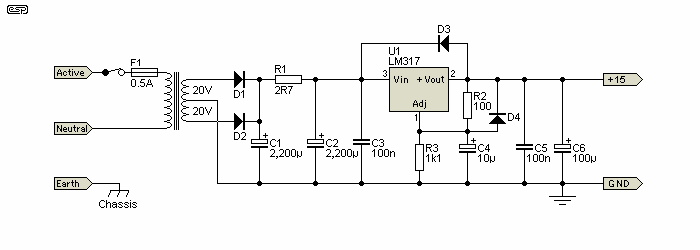
Figure 1 - LM317 Regulator Schematic
The drawing above shows the general arrangement. There's not much to it, and although not strictly needed, the extra diodes are good insurance against momentary reverse polarity which can damage the IC. The drawing shows a single regulator, wired in one of the most common configurations. Only the positive regulator is shown, and analysis will be done for the circuit pretty much exactly as shown above. Note that the large input capacitors mean that a fast change of input voltage isn't possible, so the 'Line Transient Response' shown in the graph below is not relevant. The input 'pi' (π) filter with C1, R1 and C2 is something I've used for many years, and it removes most of the high frequency harmonics from the rectified AC, and even with as little as 2.7 ohms for R1, the attenuation of even the 100Hz component is significant (about 13dB, and increasing with increasing frequency).
Most transient behaviour is measured using fast switching circuits, which may switch the output from zero to maximum current at a very high rate. For example, in the 'Load Transient Response' graph, the total switching time (load-on and load-off) is only about 2.5µs. This simply cannot (and will not) happen in an audio circuit. The load transient is shown with no output capacitance and 1µF. so it follows that if the capacitance is higher, there will be less disturbance, even at such unrealistic (for audio) switching rates.
Something the graphs fail to show is what happens when the output capacitance reacts with the response of the regulator itself. It has a frequency response that falls at 6dB/ octave, so resembles an inductive source to the load. This can interact with the output capacitor and cause ringing. However (and this is important), if the current only varies comparatively slowly (or even barely at all), then there is no 'transient' event that will cause any problems.
It's easy to run a simulation or take direct measurements that show ringing quite clearly, but it's essential to be realistic. There is no point designing a power supply that can cope with fast transients if they will never be encountered in practice. Naturally, it doesn't hurt if your regulator is much faster than it needs to be, just as it's quite alright if it can provide 10 times the current needed by your circuit. However, trying to ensure that it can do either of these things will not make it sound any 'better'. Any claim that it will change the sound should be taken with a (large) grain of salt, and most such claims have never been verified in a double blind test (what a surprise).
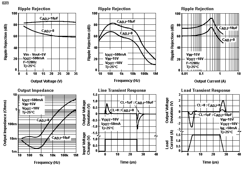
Figure 2 - LM317 Transient Performance [ 1 ]
Now, let's have a look at the various graphs to see what they mean. Ripple rejection is fairly straightforward, and is a measure of how well mains ripple across the filter capacitor (C1 in Figure 1) is removed by the regulator. Since the graphs originate in the US, 120Hz is used (rather than 100Hz which most of the world uses). The difference is probably so small that it will be hard to measure, so that's not a problem. Ripple rejection is influenced by the adjustment pin bypass, and as seen a value of 10µF is normally quite sufficient to allow better than 80dB ripple rejection.
The situation isn't quite as rosy for higher frequencies, but this will normally not be an issue for a linear supply. If you are regulating the output of a switchmode supply then the second graph needs to be consulted, but otherwise it can be ignored. From the third graph, it's also apparent that ripple rejection depends on the output current. There's nothing you can do about that, and the performance is perfectly alright over the full current range.
The next graph (Output Impedance) is more telling, and is something you may need to consider. Above 500Hz, the output impedance rises at 6dB/ octave, and this simulates an inductive output impedance. It is this 'simulated inductor' that can create problems. In terms of regulation, the output will be affected by rapid transient load current changes. As already noted, this tends not to occur with the vast majority of linear circuitry.
Line regulation describes how the regulator circuit reacts to sudden changes of the input voltage. This is normally quite uncommon, especially if the bulk (filter) capacitor is properly sized. To change the voltage across a 2,200µF capacitor quickly (such as by 1V in a few nanoseconds as shown) requires a lot of energy, and is unlikely in any real circuit. However, it's also a warning that you may get excessive noise at the output if the input is derived from a switchmode supply with inadequate output filtering.
The load regulation graph shows what the output does when a load is suddenly connected or disconnected. No circuitry is instantaneous, and it takes some time (in microseconds) for the IC to realise that the output voltage has fallen due to loading, and recover to the designed output voltage. With fast transients (and inadequate output capacitance) the output may 'ring' at some high frequency (6kHz up to perhaps 60kHz). with a damped oscillation. The load regulation graph hints at this, but doesn't provide enough detail to be useful.
If you have a circuit that has high peak current with a rapid rate of change, a reasonably large output capacitor (220 to 2,200µF) will generally reduce any ringing to negligible levels. You also need to place a bypass cap close to the switching circuit itself to counteract lead or PCB trace inductance. This is especially important if the circuit is some physical distance from the regulator. The amplitude of the oscillation is generally fairly low, and will rarely exceed ~50mV peak in either direction (above/ below the set output voltage). A decent sized output cap will ensure the most stable output.
There is another problem that might cause issues, and that's the behaviour of a series inductor/ capacitor (LC) circuit. This might create a 'noise peak' at a frequency determined by the 'inductance' of the regulator IC and the output capacitor. This peak is (theoretically) inevitable (and not mentioned in any of the datasheets), but I don't know of a single case where it's caused a problem. I have had exactly zero reports from anyone (ever) of any issues due to this phenomenon.
While doom and gloom may be predicted if you don't take appropriate care, in reality it's generally a non-issue. Analogue ICs (e.g. opamps) draw current continuously, so they provide some damping of the LC circuit created by the IC and its output cap. Since there are no radical transient current loads with most analogue circuits, there will be little or no ringing at the output of the supply. It's actually difficult to determine the apparent output inductance of the LM317. The output impedance graph implies that it's a lot lower than the measurements show (Zout is shown as around 33mΩ at 10kHz, giving an inductance of about 530nH).
Due to the internal high frequency rolloff, the output appears inductive, and this reacts with the output capacitor to create a noise 'peak'. Being an active circuit, there is some unpredictability involved. Note that the measurements shown below assume no external load, so are 'worst case'. An external load will damp the resonance peak somewhat. Expect a load equivalent to ~200 ohms (50mA at 10V) to damp the peak (with small capacitors - less than 1µF) by around 3dB referred to the maximum, which is about 19dB at 22kHz as shown on the graph. The load is less effective with higher capacitance because capacitive impedance is so much lower (10µF has a reactance of only 2.6 ohms at 6.25kHz).
While I have no reason to doubt the results obtained in the following chart (the source is certainly reputable), I have not been able to reproduce the results shown. In general, if you have a potential noise issue then it would be wise to run some tests of your own, but I have never encountered any 'untoward' noise problems using any voltage regulator, and I have used rather a lot of them in the many years I've worked in electronics design. Unfortunately the original article was rather sparse on details, and failed to provide info on the units used in the noise voltage scale. The exact test methodology wasn't discussed either, so the graphs should be taken as 'this may happen', rather than 'this will happen'.
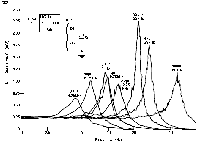
Figure 3 - LM317 Noise Peaking [ 2 ]
Based on the above graph, the inductance at the output of the LM317 is about 65µH (a 10µF cap and 65µH inductor are resonant at 6.25kHz - close enough), and that's the peak seen in the graph. The effective inductance is not constant, and it varies with load. Using a low ESR (equivalent series resistance) capacitor for CL will make the problem worse, and a 'standard' aluminium electrolytic is normally the best choice. Although the effective Q of the regulator's output inductance is not especially high, as seen in the graph, you can still get a substantial noise peak.
Given the noise specification provided in the LM317 datasheet, I've 'calibrated' the noise levels, based on a 'typical' output noise of around 250µV for 10V output. What does become apparent is that high ESR capacitors are likely to cause less of a problem than specialised low ESR parts. With the LM317 (and similar ICs), a low ESR will not cause oscillation, but it may increase the size of the noise peak and/ or ringing amplitude with a transient load. Be aware that the situation with LDO (low dropout) regulators is very different. See the Low Dropout Regulators article for more details about them (they can be very fussy!).
One way you can test for this is to apply a transient load, pulsing the current at a suitable rate (say 1kHz), and look for any ringing (damped oscillation). If present, there is also some noise peaking, because the two are directly related. The frequency where you see ringing indicates a resonant peak, so if you see a damped oscillation at (say) 6kHz, then it's likely that there's also a noise peak at that frequency.
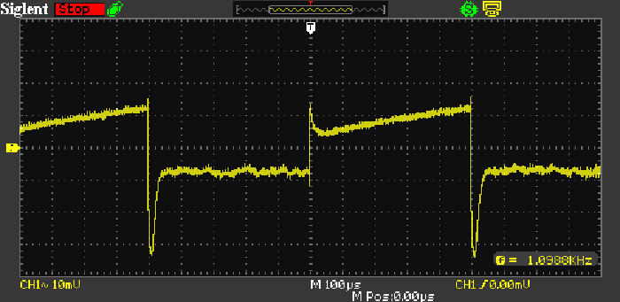
Figure 4 - Transient Response Of 7815 Regulator
Because transient response is a certain indicator of any sign of a resonant circuit created by the regulator and its output cap, I did a quick test. Ringing indicates resonance, with the frequency corresponding to the frequency where noise will be at its worst. I tested a 7815 (the positive half of a P05-Mini), and the transient response is shown above. It's not perfect - no regulator ever is, but the transient response is about what I'd expect given that the output cap is only 10µF. The capture was done as the 27mA load was connected and disconnected, and the AC component is about 20mV peak-peak. There is no sign of instability (ringing). Lead lengths were kept short (less than 20mm) to prevent spurious issues with stray inductance. A larger output cap will improve the overall stability - especially the initial ~40mV dip (that's due to the time constant of the output cap and load resistance - 5.6µs).
Note that no audio circuit can or will ever impose a load such as used above. The rise and fall time of the output current is in nanoseconds - I used a very fast 1kHz squarewave to turn on the transistor.
A common recommendation is to use two or more capacitors in parallel, with each having a different value. While you might think this could spread the resonance and reduce its effects, it does no such thing. A 100nF cap (for example) in parallel with a 10µF cap behaves more-or-less identically to the 10µF cap by itself, even if one or both has a significantly higher/ lower ESR than the other. You may read that the values should be 'non-harmonically related', meaning that they shouldn't be half, double, three times or any other simple multiple.
Just like any other caps in parallel, the larger (or largest) value will dominate, but the performance is much the same as you would expect of paralleled capacitors. The total value is the arithmetic sum of the individual values used. The only place where it's common (and useful) to use unequal value caps is when bypassing opamps and RF circuits. A monolithic/ multilayer 100nF ceramic should be in parallel with the supply pins, and it's usually wise to include 10µF electros (usually between each supply and ground) where the DC enters the PCB. This has nothing to do with snake oil, but compensates for the track and wiring inductance that may otherwise cause instability.
Paralleled caps are also common in RF circuits, where the high frequencies involved make even small stray inductances likely to cause major problems. Significant signal degradation can be caused by only a few centimetres of wire. For this reason, bypass caps should always have the shortest leads possible, and be as close to the circuit as physical layout can achieve. With RF circuits, the self-inductance of an electrolytic, polyester (or other film) cap may become significant, and a small ceramic (SMD for minimum self-inductance) may be used in parallel.
Given the very low output impedance of most regulators, it should come as no surprise that simply adding a large output cap doesn't significantly reduce the output noise (residual ripple in particular). Even adding a 2,200µF cap will not affect 100/120Hz noise at all, but if you are unlucky, you could easily end up boosting the noise level at a harmonic of the mains frequency. Because the overall noise (and hum) levels are already very low, you almost certainly will not notice such a boost if it happens.
Virtually all common regulator ICs have an internal 6dB/ octave rolloff starting from around 10Hz to 500Hz or so. That means that all of them have an effectively inductive output impedance. It follows that the same caveats apply, regardless of the type of regulator you use. While the effects can (perhaps) be reduced somewhat by using a fully discrete or opamp based regulator circuit, there are no good reasons for doing so. There's no doubt that the effects shown are real, but equally they rarely cause anyone a problem.
Consider that there are millions of regulator ICs in use throughout the world. Of these, very few indeed are considered troublesome in any way, by any user. Some will have been designed using the wrong type of capacitor at the output (e.g. a low ESR type), and most just use standard electros of varying capacitance. Anything from 1µF to 220µF is very common. While countless people will insist that the DC somehow has a 'sound', unless it's very noisy it has no such thing. Opamp circuitry can (and does) remove much of the supply noise (that's called PSRR - power supply rejection ratio), but it does fall with increasing frequency.
In theory (and based on the logic of some), every piece of audio gear built should be noisy, with an audible background hiss that won't go away. To an extent, this is true, except that in most cases it's at such a low level that it's not audible unless you put your ear against the tweeter. Since most of us don't listen to audio that way, it's apparent that it must make no difference to what we hear, and indeed, that is true. Headphone amps are a case in point. Headphones are usually very sensitive, yet most dedicated amps driving them are as close to 'noiseless' as you're likely to find.
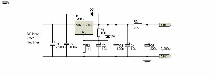
Figure 5 - RC Network Reduces Noise To Negligible Levels
If you have a particularly intractable noise problem, then the easy way to fix it is to use the circuit shown above (varied according to current demands). As shown, the circuit is specifically intended for circuits that draw a reasonably consistent current, regardless of signal level. The values given are suitable for circuits drawing up to 100mA, and although regulation is not as good as it would be without the series resistor, that usually doesn't matter.
The series resistor isolates the regulator (I showed an LM317, but it can be any type you like, including an LDO regulator). The capacitor is no longer able to have any significant interaction with the regulator's inductive output impedance, and noise is rolled off from a frequency determined by ...
f = 1 / ( 2π × R × C )
With the values given, that's 268Hz (220µF) down to 27Hz (2,200µF), but you can change it to whatever you like. This arrangement is not suitable for use where there is a large current variation, unless you are certain that the voltage change won't upset the following circuitry. It may be unwise to use this circuit for powering dual opamps that have each opamp section devoted to different audio channels unless you use a large capacitance. In most cases I would expect no problems. The 2.7 ohm resistor affects the voltage regulation with varying currents, and the output voltage will fall by 270mV for each 100mA of current drawn.
The values given attenuate the noise at 6.25kHz by 30dB below the low frequency noise level with 220µF, and obviously a great deal more if you use a larger value. Not only is the peak seen in Figure 3 removed entirely, but above 268Hz (or 27Hz) all noise is rolled off.
Another option is the use of LDO regulators, with some specified for extremely low noise. Unfortunately, some of these are available only as positive regulators, and no negative version of the same basic type exists. Many are also limited to relatively low voltages (+5V or -5V output), but higher voltage versions are available. The higher voltage versions are unlikely to be significantly less noisy than standard regulators.
Regulators are not as simple as they appear (I doubt that anything is as simple as it appears  ), but in the vast majority of cases they can be used with most circuits without any concerns whatsoever. Output impedance, transient response, noise, etc. are all real, but generally do not affect what we hear. In the vast majority of cases, careful measurements will be the first indicator if there is anything amiss. How good your results are depends on the capabilities of your measurement system, but you need to be aware that there are no known problems with any circuitry that are audible but not measurable.
There is no doubt that some potential problems can be below the limits of many measurement systems, but the only way to be certain that a change has improved (or made worse) the sound is by a double-blind test. That generally means that you need two samples, one 'tweaked' and the other left 'standard', so you can make direct comparisons, in real time, without knowing which system you are listening to. You can use the ABX Tester or AB Switch Box projects to run your tests (the AB Switch Box is the simpler of the two and works very well).
There is no doubt that the measurements and regulator behaviours described here are real, but the only thing that should be of interest is "does it make an audible difference?". Most of the time, the answer will be "no", but there may be some circuitry that benefits from an ultra-low supply noise level. Where this is found, it's quite likely that the circuit itself is at fault, rather than the power supply. At times like this, simulations and published info have to be verified, so I attempted to do just that, but I was unable to verify an actual noise peak at the regulator's output at any frequency using my scope and FFT analysis.
Although there is some risk of a noise peak, it isn't necessarily going to show up in real life. The quick test I did to see if I could replicate the 'noise peak' was unable to show anything meaningful. You will see evidence of the same effect in other articles [ 3 ] but usually at higher frequencies and lower amplitudes than the above graph implies.
If you want to get the lowest noise possible, consider using a capacitance multiplier, as shown in Project 15, but adapted for lower current. This is a very effective way to get the equivalent of several Farads of capacitance (assuming you think you need that much). The cap multiplier circuit is placed after the regulator, and the regulator's output voltage adjusted to get the desired final voltage. You will need a higher input voltage than normal, so for 15V DC you would typically use an 18V or 20V transformer.
Ultimately, it will rarely be the regulator that's the cause of noise problems. Ground loops or poor grounding practices can cause low frequency hum or buzz, and RF interference from any number of possible sources are generally going to cause many more problems than voltage regulators. However, this information may come in handy (and it's difficult to find), hence its inclusion on the ESP website.
The graphs shown (Figures 2 and 3) are based on those in the referenced documents, but have been redrawn to make them easier to read (the originals were anything but).
 Main Index
 Articles Index