
|
| Elliott Sound Products | Project ABX |
This project describes the construction of test equipment for double-blind or ABX testing of source components - preamplifiers, tuners, DACs etc. or even, if that is your particular vice, interconnects. It builds on the work done by Phil Allison described in Project X. I recommend that you read that project description before you commence this one. If you do not like what you read there, then you might as well stop reading at this point.
Double-blind and ABX tests do not allow the listener to know which component they are listening to, and furthermore don't allow the test controller to know either. This guards against visual cues to the audience (including body language).
There is information on the principles behind ABX testing elsewhere on the Net, therefore, I intend to give only the briefest description here.
An ABX test allows the listener to select either A or B as many times as they like, and ultimately decide which of these is X, where X is randomly selected by the equipment to be either A or B, and the responses are logged for correlation when the test is complete. For example, a 1000Hz tone is assigned as A, and a 1500Hz tone as B. Random selection determines which of these is X. Listen to A then X, listen to B then X, and decide if A or B sounds like X (this would be a rather easy test for anyone to get right, of course- but if B were to be 1001Hz it may be more of a challenge).
True ABX testing is normally not easy and uses a microcontroller or a PC to interface to the switching module. This was not an option as the project is meant to be simple and inexpensive. The simple remote control (part 2) requires an operator to control switching between A and B and to whom the active channel is known. However, if you proceed to build the double-blind remote (part 3), then the unit is a true ABX comparator - you select the next test in the sequence with the 12-position rotary switch and then have the opportunity to decode if X is input A or input B. This is 'double-blind' because the sequence is not known until the test has been completed.
With the basic unit, two pieces of equipment (for example, two preamplifiers) are under comparison (A and B). They are fed from the same source. The audience hears first A and then B. Thereafter, the test controller selects either A or B as X and repeats the test for up to (about) twenty iterations, changing from A to B at his or her whim, and the audience is required to write down which they think it is for each iteration. Thereafter, the results are analysed to find out whether the audience was able accurately to identify which piece of equipment was in use at each iteration of the test.
There is no requirement that A and B are selected the same number of times during any single test. In fact, a test controller once ran a whole test with A. None of the members of the audience selected 'A' for each iteration. I leave you to consider what that result says about people's confidence in their ability to identify different components.
The project is in three parts of which you must build at least two. I recommend that you build only parts 1 and 2 to start with. You might find that your experience of this piece of test equipment is so infuriating that you will regret the time spent on building part 3 if you proceed with it immediately.
It is vitally important that the output level of the devices under test is equal. A difference of 1dB is normally sufficient to bias the test, normally in favour of the louder channel. Therefore, you will need a test-tone CD for calibration purposes if using CD as your source or an LP with test tones if using vinyl. If comparing tuners, you will probably find that tuning in the white noise between stations is the only way you can calibrate the two pieces of equipment. You will also need a multimeter. Unless you are using an expensive true RMS digital multimeter, you should not use a test tone above 500Hz. With an analogue meter you can use a higher pitch but I do not recommend that you go higher than 1kHz. 1dB represents a voltage between 891.25mV and 1.122V, assuming a reference level of 1V (RMS). You should aim for better than ±50mV variation for a 1V signal. This equates to ±25mV for a 500mV signal.
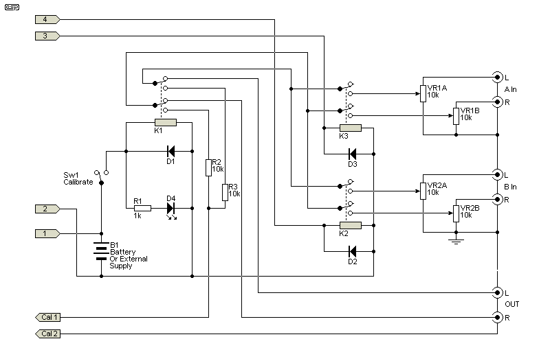
The circuit diagram should be fairly easy to understand. There is nothing difficult about it, and no electronics are involved in the audio path.

Connections 1 through 4 go to either of the remotes and should be wired to a four-pin connector. The relays K1-3 can be low current types. The battery must match the voltage of the relays. I used 6V DPDT relays. K3 and K2 are used to select input A or B respectively. K1 mutes the output for calibration purposes. You could replace K1 with a switch if you wish but you then have to run more wires inside the box. The voltmeter connects externally to the two pins marked "Calibrate". Pots are used on both inputs solely for consistency - if a pot is used on only one of the inputs, then some people may use this as "proof" that the device modifies one channel and not the other, and this can be used as an excuse as to why the results failed to correlate "correctly".
The circuit should be built on a piece of Veroboard or similar and mounted in a shielded metal case. SW1 and D4 are mounted on the outside of the case, as are the connectors for attaching the voltmeter, the 4-pin connector for connection to the remote and the RCA plugs for the A and B inputs and the X output.
If you are proposing to use only the remote described in part 2 you do not need to take any precautions to ensure that K2 and K3 are inaudible at the listening position. However, testing using the part 3 controller requires that the relays be inaudible at the listening position. To do this you will have to mechanically decouple the circuit board from the case and also use some acoustic dampening material in the case. See note 2 below.
WARNING: I do not recommend that you omit the muting part of the circuit. When you come to use this device, you will first choose the music you wish to hear for the test and establish a realistic listening level Then you mute the output and use the 0dB level test tone to adjust the levels of both channels to the same voltage. You will probably find that the steady-state voltage is greater than 2V RMS. Unless you have monster loudspeakers, a tone at this level, fed through a power amplifier with a 30dB gain (which is common), will probably destroy your speakers and will do nothing for your hearing.
I have found that different pieces of music require different volume settings to establish a realistic listening level. An AB test where you are wincing at the volume or straining to hear the music is of no use. The calibration mute circuit has been included to speed up the recalibration between tests using different pieces of music.
That said, however, if you wish to go through the process of either (a) turning off your power amplifier(s) or (b) disconnecting your loudspeakers each time you need to recalibrate, you can omit this part of the circuit. However, you have been warned. (And you have forgotten to reconnect the speakers and/or turn on the amp(s) before proceeding with the test.)
VR1 (and optionally VR2) is included for trimming of the voltages during calibration. Obviously, the volume should be set using the preamps' volume controls (if those are what you are comparing). However, if you are testing preamps, both of which have stepped volume controls, you might find it difficult to match the voltages at your realistic listening level. That is what VR1 is for. If you don't expect to be doing this, VR1 can be omitted. For A-B testing of other equipment, such as tuners, VR1 will be required.
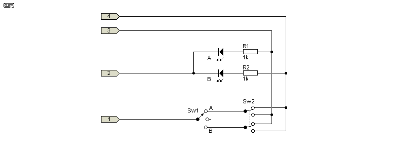
This is a simple selector which can be built in a small plastic box and is connected to the controller using four-core cable. Heavy duty cable is not required. The cable should be long enough that the operator can sit further away from the source equipment than a person in the normal listening position. SW1 is a 3-position rotary selector switch used to select A or B or null (centre position). The channel selected is indicated by the relevant LED. SW2 is a DPDT toggle switch which flips the channel from A or B or vice versa. This can be used for simple A-B testing. I have found that there is an audible break when a toggle switch is used for SW2. You might find no break is audible if you use a rotary selector.

To do an AB test with this remote you will need a (patient) assistant. The procedure (using as an example two preamps as the devices under evaluation) is as follows:
| a) | Use Y-splitters to connect the source equipment to each of the preamps. Connect the output of one preamp to input A and the other to input B on the controller box. Connect output X to your crossover or power amplifier. |
| b) | Select one of the channels and play some music adjusting the volume on that channel to the desired realistic listening level. |
| c) | On the controller box, mute the output using the switch provided. Connect a voltmeter to the calibration terminals. Insert the test tone CD, play a 0dB calibration tone and note the voltage. Use SW1 on the remote to change to the other channel and adjust the volume so that the same voltage is displayed. If stepped volume controls are in use, you might need to trim using VR1 on the controller. (Set VR1 to the maximum before calibrating and use it to attenuate the voltage.) Once the voltage is adjusted, remove the test-tone CD and replace the music CD and turn off the muting switch. Do not touch the volume controls again for the duration of the test. |
| d) | Assume your normal listening position. You will need a pencil and paper to record your choices. |
| e) | The person conducting the test (the operator) should sit out of view of the listener with the remote to hand. The listener must not be able to see the LEDs on the remote. Decide which one of you controls the source and how many iterations of the test will take place. |
| f) | The operator selects first channel A and the listener familiarizes him/herself with the particular characteristics of the preamp connected to that channel. Channel B is then selected and familiarization of that channel takes place. |
| g) | The operator now selects either channel, the music is played and the listener to writes down whether A or B is his choice for X. The listener does not divulge to the operator his choice. The test is then continued for the number of iterations agreed upon, with the operator selecting either A or B. I recommend that, to avoid any unintentional bias, the sequence of changes be determined in advance of the test by some random operation (tossing a coin, throwing a die, for example). The operator should carry out this random operation prior to conducting the test. |
| h) | The last iteration of the test having been concluded you may either check the results or return to step (b) with another piece of music. |
The listener's choices are then compared with the operator's notes of the actual channel in use during each iteration. It should be immediately apparent whether any there is any correlation between the listener's choices and the actual selections.
If you do not have a patient assistant, or patience has run out, you might wish to proceed to ...
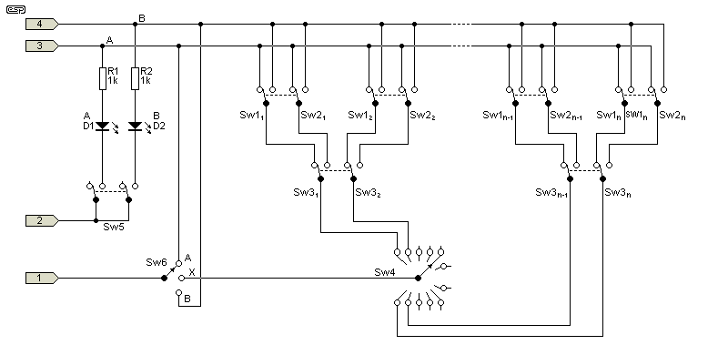
This remote uses cascaded SPDT slide switches to set up an A-B sequence which can be used blind for testing purposes and then read back to check the results. It should be apparent from the schematic how this works. The separate poles of SW1 and SW2 must each connect to lines 3 (A) and 4 (B). SW3 selects between SW1 and SW2. For each position on the rotary selector SW4, three SPDT slide switches are required. I have built this with a twelve-position selector using 36 slide switches.

In the above, 'n' is the number of poles on the rotary switch. If a 12 position switch is used for SW4, then 'n' is 12, and 'n-1' is 11.
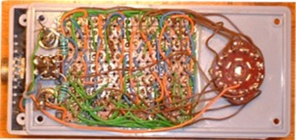
The schematic, for clarity, shows the switches SW1, SW2 and SW3 connected together in a regular sequence. However, when building this remote, the switches are hooked up in an irregular fashion so that it is not possible from the outside of the box to identify what function any particular switch has, nor how they are wired in relation to one another. The separate poles of each switch (SW1 and SW2), however, must each connect to the A and B buses. If you do not do this you will introduce a bias in favour of one of the channels. The photo shows my own unit. Properly constructed, it should look like a mess of wires, as does mine. The orange and blue wires are the bus lines, the green wires the connections between the centre poles of the SW1s and SW2s and the brown wires go to the rotary selector.

If you decide to proceed with this part of the project, I must warn that this remote is tedious to construct and you must proceed with great care because trouble-shooting an incorrect hook-up or a dry joint can be difficult. You should first wire between the centre poles of the SW1s and SW2s to the SW3s, then run the bus wires to the outside poles of the SW1s and SW2s and finally connect from the centre pole of the SW3s to the rotary selector. Solid-core or magnet wire is recommended. The remote can be constructed in a plastic case.
So how do we use this abomination?
| i) | It is connected to the control box with the same four-core connector that you made up for part 2. |
| j) | Before proceeding with the test, set up the test sequence by moving half of the total number of slide switches on the box. SW5 must be open at this time; no LEDs illuminated. |
| k) | SW6 switches selects A or B for calibration as per (b) and (c). SW5 is closed (LEDs in circuit) during this step. |
| l) | Open SW5 so that no LEDs are illuminated. |
| m) | Assume your normal listening position and use SW6 to select A and B as in step (f) |
| n) | Move SW6 to the X position. Is it A or B? Write down your choice. Proceed through all the other positions on SW4 marking down your choice each time. |
| o) | When all positions have been sampled, close SW5, rotate the selector SW4 and observe which channel was in use for each iteration of the test. Correlate your results. |
| p) | If you wish to repeat the test, proceed again from step (j). |
Notes
I hope that this little project will amuse you.
Steven Hill, August 2002
Steven has done something I had thought would only really be possible using a microcontroller or a PC to achieve. The random switching is of such complexity that it would be virtually impossible for anyone to know and remember the combinations created by each switch. Especially if assembled according to the instructions - the switches are not only capable of giving an excellent randomisation of their own accord, but if they are wired in a random fashion as you build the unit, the likelihood of being able to remember the combinations is extremely low.
Will it be worth the effort? Only you can answer that, and it depends on how serious you are about being able to tell the difference between pieces of equipment. Just like Phil's original Project "X", your first reaction may be that the unit is not working - the LED indicator that Steven included in the design to allow you to correlate the results will certainly prove that A and B are being selected, and if you are really unsure, you can always switch off one of the units under test.
All in all, this is an ambitious project, but one that every hi-fi reviewer should make (or have made) - I expect that if this were done, a great many of the glowing reviews we currently see would diminish. They may even vanish altogether.
Needless to say, the tester can be also used to verify that the expensive capacitors you bought really don't make any difference, or that all well constructed interconnects sound the same. This is all very confronting, but it is necessary if we are to get hi-fi back on track, and eliminate the snake oil.
 Main Index Main Index
 Projects Index Projects Index
 Articles Index Articles Index
|