
|
| Elliott Sound Products | Voltage Protection |
 Main IndexArticles Index
 Many electronic circuits are fairly low-cost, and the failure of a regulator may cause the supply voltage to increase to the point where some damage is experienced. A few opamps and capacitors might fail, but there's no damage that will cost the user a small fortune to fix. Others are very sensitive (and expensive), and they will be damaged or destroyed if the supply voltage increases even slightly. Logic circuits are one of those that are at risk, with 5V logic ICs pretty much guaranteed to fail if the voltage exceeds 7V (their absolute maximum voltage rating). There are numerous ICs available that are designed specifically for the job, but like so many specialised ICs made now, there may be no replacement available in only a couple of years after the product is manufactured.
This 'planned obsolescence' has become a major problem with many consumer goods, and industrial products aren't immune either. It's now common that any modern product will be almost exclusively based on SMD parts, and many cannot be repaired economically, if at all. There are specialist repairers who can fix SMD boards, but only if they can get the parts. This makes it all the more important to ensure that a power supply failure doesn't fry the main PCB(s).
Fortunately, it's uncommon for switchmode power supplies (SMPS) to fail with the output going high. It can happen (and I've seen it), and it can cause stress or failure of other parts. It can be caused by electrolytic capacitor failure, and the output may turn on and off, but with the 'on' period uncontrolled. Another failure mechanism is that the optocoupler used for feedback fails, resulting in a higher than intended output voltage. In a few cases, over-voltage protection is provided on peripheral boards to protect against SMPS failure, but all too often it's not included.
It's important to understand that there are two main classes for over-voltage protection. One (and that described here) is for electronic assemblies that rely on a well-regulated DC power supply, and the other describes mitigation for mains over-voltage conditions caused by supply network disturbances or lightning. Another class of device protects electrical gear against mains under- or over-voltage, and an example of this type of circuit is shown in Project 138. Protection against lightning (in particular) is much harder, because the energy available can be very high, and virtually nothing will protect equipment against a direct (or close by) lightning strike.
A comment I've made before is the answer to the question "Why doesn't lightning strike the same place twice", with my answer being that "The same place isn't there any more!" This isn't strictly true of course, but I used to have a large tree next door to my home that was hit by lightning, and it was literally blown in half. (For what it's worth, it survived - at least until the block of land was sold and the tree was removed.) As for the saying itself ... it's a myth. Lightning does strike the same place many times if it's designed for the task and/ or isn't destroyed.
If you have a system that uses microprocessors, ASICs (application specific ICs), FPGAs (field programmable gate arrays) or other expensive circuitry, over-voltage protection should not be an afterthought. All too often it's left to the power supply to always provide the right voltage, with sufficient current to ensure proper operation. If your circuitry draws a few amps at 5V (or other voltage as appropriate), then the supply should always be capable of supplying more current than the circuitry draws. A power supply that's on the edge is working hard all the time, and is more likely to fail than one that's over-engineered for reliability and long life.
However, any power supply can fail, and the results can be catastrophic if the failure mode means that the voltage increases beyond the maximum allowed for the ICs. Most analogue audio systems can't tolerate excessive voltages either, but the devices used in most gear are relatively inexpensive, and failures are uncommon. Even if a linear regulator IC does fail, the ICs can be replaced fairly cheaply. This is not the case when costly DSP (digital signal processing) devices or other expensive semiconductors are used though, so over-voltage protection is still a consideration. Doubly so if the supply is a switchmode type, as failure is somewhat more likely than a simple (well designed) linear supply.
Although generally considered 'brutal', the best over-voltage prevention device is a crowbar circuit. It's so-called because it's the electrical equivalent of dropping a crowbar across the supply terminals, with no consideration for any subsequent damage to the power supply. The supply has already failed (hence the over-voltage condition), so a short-circuit is the safest option to protect your circuitry. In some cases you may need to take additional precautions to ensure that the (very) sudden absence of supply voltage doesn't cause additional damage. A published amplifier design from many years ago used a crowbar circuit to protect a power amplifier from overload, but due to a design error in the amplifier, when the crowbar operated, the amp failed as well. This was not the desired outcome!
Under-voltage protection is less common, but there are applications where it can be very important. An example (and the one used in Section 6) is a motor, which cannot start under load if the voltage is too low. This can lead to failure in some cases. Under-voltage conditions can also cause circuits to misbehave, and while it usually doesn't cause any damage, it may still have an undesirable outcome.
You often hear people claim that a 'voltage surge' caused some kind of damage to equipment. The term is over-used and generally meaningless, because it fails to specify anything tangible. There are two different types of overvoltage, ESD (electrostatic discharge) and a condition where the voltage exceeds the nominal by some (excessive) percentage. ESD is very high voltage, but usually doesn't supply much energy. ESD is often responsible for damage to MOSFET and CMOS circuits, and is almost always the result of poor handling procedures by the assembler. It's counteracted in a production environment by the use of anti-static wrist bands, conductive flooring materials and the use of conductive foam (or carrier tubes, etc.) for susceptible parts. For test procedures, there's a 'human body model', where the human body is modelled by a 100pF capacitor and a 1,500Ω series resistance. During testing, the capacitor is fully charged to 2kV, 4kV, 6kV or 8kV, depending on the test procedure being used. The charged capacitor is discharged through the resistor to the DUT (device under test).
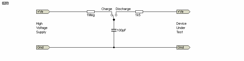
Figure 1.1 - Human Body Model
Static discharges can occur when equipment is in use. Not always because of static discharge per se, but often when a switchmode power supply is used to provide power to a circuit. Most SMPS are 'floating', and are not earthed/ grounded, and are classified as 'double insulated' (Class-II [IEC]). An internal capacitor (Class-Y1) bridges the insulation barrier, and is used to minimise EMI. The output of these supplies usually has an AC voltage present at the output, typically at around 90V with 230V mains, or 45V with 120V mains. This is highly variable though, and it can be more or less depending on the supply. If an input stage is connected to this voltage before the earth/ ground connection is made, it's surprisingly easy to damage the input device. High input impedance circuits are more susceptible than those with low impedances (not surprisingly).
I suppose one could call this a 'voltage surge', but it's a specific condition that is easily modelled and tested. It's not a 'surge', but a very short voltage 'spike'. The term 'surge' implies something that changes relatively slowly (a couple of milliseconds is 'slow' in electronics). In reality, surges are very uncommon. The AC mains is subject to long and short-term variations, but to qualify as a true surge it would have to be well over the nominal maximum (> 15 to 20% or so) and last for at least a few cycles.
Any manufactured product will (should) be able to handle the full mains variation of ±10% from nominal. Many SMPS can function normally with anything from 90V to 260V AC, 50/ 60Hz. What happens if the regulation fails depends on the supply, and some may produce an output that's much higher than it's rated for. A 12V supply may provide 20V or more if the regulation fails, and if your equipment can't handle that safely then it's probably going to be damaged. This condition can't be called a 'surge' either, as it's a constant excessive voltage that's present when the supply is powered. Some might have an overvoltage protection circuit built-in, but don't count on it! I've examined countless SMPS and have yet to see one with any (robust) form of protection. However, most failures result in no output.
Another area where overvoltage conditions are common is in automotive applications. The most common issue you'll see referred to is a 'load dump'. This occurs when a high-current load is disconnected, and the alternator's output can rise to a voltage that's far greater than the nominal 12V (or 24V for most trucks). Based on the standard (ISO-16750-2), a 12V system is tested with 10 pulses in 10 minutes, with a voltage of 101V in series with a resistor of between 0.5Ω and 4Ω. The clamping device will usually be a TVS diode, selected to be able to handle the power, and the peak voltage is usually clamped to around 35V. This is still much higher than the nominal 12V (usually up to 14.4V when the battery is charging), and it's expected that circuitry intended for automotive use will be able to handle at least 40V 'events'. The automotive environment is hostile, and electronics that can't handle the voltages, heat and vibration are not long for this world.
The two most common single components for (transient) overvoltage protection are MOVs and TVS diodes. MOVs are bidirectional/ bipolar, and TVS diodes can be either bidirectional or unidirectional (unipolar). MOVs are most commonly seen across the AC mains input, and can suppress mains transients caused by network faults, (distant) lightning, etc. However, note that a nearby lightning strike is perfectly capable of destroying any form of protection.
In some cases (less common today) gas arrestors are used. These are hermetically sealed, with a pair of electrodes in an inert gas. They are capable of very high discharge current, and are often used in telecommunications and (less common perhaps) antenna installations. Gas discharge tubes are available in a fairly limited number of voltage ratings, and usually the minimum voltage is around 75V. I don't intend to cover these here, as it's a rather niche market and they're not common in consumer electronics.
A very simple overvoltage detector uses nothing more than a zener diode and perhaps a transistor and/or optocoupler to provide a 'fault' signal that tells the SMPS to shut down. This simplified approach has many disadvantages, because the supply will turn on again after the power is cycled ("Turn it off and back on again" is a standard 'troubleshooting' technique for electronic equipment). A common approach is the crowbar protection system, which uses an SCR (silicon controlled rectifier, aka thyristor) to short the supply if it goes above a preset threshold voltage. The risk of fire (or further damage) is mitigated by using a fuse. When the SCR is triggered, it will attempt to draw a very high current, and hopefully the supply can provide enough current to blow the fuse.
There are examples of this technique on the Net, and it's as close as you can get to being foolproof. There are others as well, often using MOSFETs to switch off the supply if it's out of range (too high or too low). While the ICs designed for this purpose will work as intended, they rely on comparatively fragile switching devices (MOSFETs vs. an SCR). An SCR such as the BT151 or C122D (which I tested) are not powerhouses (12A, 8A [respectively] rated current in a TO-220 package), but they can handle 200A or 120A for 10ms. Very few power supplies will be able to manage that much current, although an electrolytic capacitor can provide that easily into a short circuit. However, there may not be enough stored energy to blow a fuse. There are many suitable SCR types, with some costing less than AU$1.00 each.
Naturally, there are other methods suggested that are (at best) ill-conceived, and while some might provide a small level of protection, they are anything but foolproof. Simple pre-regulators and other similar methods lack precision, and may also be far too slow to protect sensitive parts. You may also see electromechanical relays suggested, but they are not fast enough to protect anything. Even a fast relay will take at least 2ms to activate (most take longer), and that simply isn't fast enough. Zener diode protection schemes (of which there are many) are pretty much a waste of space, and cannot be recommended unless your requirements are very relaxed. A high-power zener diode will likely cost as much as an SCR based crowbar system, but it can never protect as well.
The biggest problem with a zener 'protection' scheme is power dissipation. If a 1A, 5V power supply is used for a microcontroller project, should it fail 'high voltage' due to a fault in the feedback path, it may try to output 7-8V at a minimum of 1A. A 5.1V zener diode would conduct, but it will dissipate at least 5.1W, but probably more. We'll assume a 5W zener, carrying 1A, and the dynamic resistance (from the 1N53 series zener datasheet) is 1.5Ω The zener voltage will actually be closer to 6.6V under these conditions, so any thoughts of real protection are imaginary. Zener diodes can be 'boosted' with an external power transistor, but it's still a bad idea. The details for the 'boosted zener' are shown in the ESP application note 'AN-007', but to be effective any zener 'protection' scheme needs a limiting resistor, which reduces the voltage available to your circuit and dissipates power.
Detection methods used involve either a simple comparator (over-voltage detection only) or a window comparator, which provides an output only when the monitored voltage is within the valid 'window'. If it's above or below the window thresholds, the detector output is in the 'invalid' state (which can be high or low, depending on the way the circuit is configured). For information on these often ignored components, see 'Comparators, The Unsung Heroes Of Electronics' (an ESP article).
It's very common to see TVS diodes used for ESD (electrostatic discharge) and/or 'surge' protection. It's very important to understand the difference between these 'events', and to be aware of the characteristics of TVS diodes. Like all components, they cannot handle infinite power, and the maximum current rating is dependent on the duration. A short (< 10µs) pulse (ESD) is very different from a longer 'surge', which is often shown as current vs. the number of AC cycles or rectified half-cycles. Waveforms are defined in IEC61643-123 (10/1000µs), and some datasheets also provide a specification referenced to IEC 61000-4-5 (8/20µs).
TVS diodes are not exact. They are far more predictable than MOVs (metal oxide varistors), but they both have internal resistance that determines the maximum voltage above the 'clamp voltage' shown in the datasheet for a given current. A nominal 6.8V TVS can vary between 6.45 and 7.14V at the 10mA test current, and may have a rated 'stand-off' voltage of around 5.80V (the maximum continuous voltage applied to the diode). All maxima have to be derated for elevated temperature and/or longer surge times. For example, a (nominal) 6.8V TVS such as the 1N6267A can handle a peak current of 143A, but the voltage at that current is 10.5V. This indicates an internal dynamic resistance of just under 26mΩ.
If you intend to use a TVS diode for protection, you must verify performance from the datasheet, and ensure that you don't exceed any of its ratings. In the case of a regulator failure the TVS diode may be considered sacrificial - if the PSU develops an over-voltage fault, the TVS diode will fail (almost always) short-circuit. The maximum long-term current has to be limited in some way, such as a fuse, PTC thermistor (e.g. PolySwitch or equivalent) or an electronic fuse (see Electronic Fuses).
Almost without exception, the first 'line of defence' is a regulator. It can be an IC type as shown, or it may be discrete. In some cases, there may be two regulators in series, with one to provide (for example) 12V and another to power 5V devices that are part of the same circuit. Mostly, this works out well enough, but the bit that's missing is circuitry to detect if the regulator fails. This isn't common, but it certainly does happen. One cause is not including an adequate heatsink, so the regulator runs hot. The other is to have an input voltage that's too close to the maximum allowable for the IC used. The 78xx series regulators are rated for a maximum input voltage of 35V, and if your input voltage is close to that with the nominal mains voltage (230V or 120V AC), a mains increase of 10% will result in an input voltage of over 38V. The regulator might survive, but it also might not. The failure mode for most semiconductors is short-circuit, so instead of 5V output, it becomes 38V!
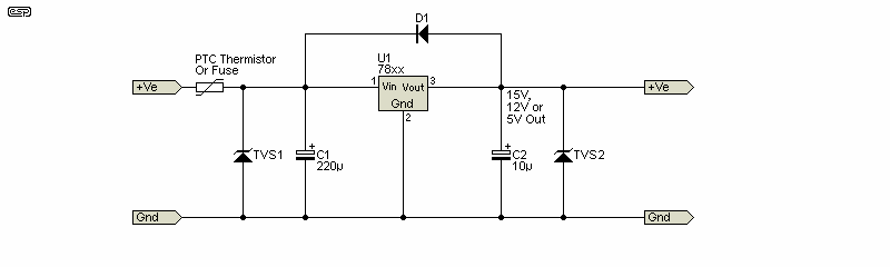
Figure 3.1 - Simple Regulator Circuit With TVS Diode(s)
For most applications, it's unlikely that one would rely on a single regulator device to obtain a low output voltage from a 35V supply, and there is usually a secondary low voltage supply provided for the regulated low voltages. However, if cost is the only consideration (and/ or the constructor reads the datasheet and thinks s/he can get away with it), then it's quite possible. The problem is that if (when?) the IC fails, so does all circuitry that relies on the regulated voltage(s). The recommended input voltage is up to 25V. The input TVS (TVS1) would typically be rated for at least 20% more than the maximum expected unregulated input voltage, and the output TVS (TVS2) rated for no more than 10% above the required output voltage.
The use of a 'PolySwitch®' [ 2 ] or a fuse means that the main power supply is not subjected to a permanent overload if either TVS diode conducts heavily. Neither is especially fast, but a Polyswitch will reset when power is removed. A fuse is permanently open after a fault, and (if it's internal) it won't be replaced until the fault has been identified and (hopefully) fixed. Either protective device has to be rated for the normal current drawn by the downstream circuitry. Be careful if you use a PolySwitch, because they are sensitive to the temperature inside the equipment. The current ratings shown in the datasheet are at 25°C. All circuits shown below with a fuse can use a PolySwitch if preferred.
Even if the input voltage to the IC regulators is within acceptable limits, that does not guarantee that no failures will occur. The simple reality is that semiconductors can and do fail, and if you have expensive circuitry 'downstream', a regulator failure ensures that many other ICs will also fail. Even if they appear to have survived, it's probable that there will be degradation and performance will be impacted. The TVS diode (whether unidirectional [unipolar] or bidirectional [bipolar]) must be selected to suit the regulator's output voltage. Low-voltage TVS diodes are mostly unidirectional and SMD, so the choices are somewhat limited. As noted above, a TVS diode is not a precision part, so relying solely on a TVS for protection may be unwise. Limited long-term power dissipation means that a fault will almost certainly cause a TVS diode to fail - hopefully short-circuit.
The only way to ensure that downstream parts are not damaged is to employ additional circuitry to detect an over-voltage, and remove the supply voltage before it causes damage. In the examples that follow, I've shown only positive circuits with the exception of Fig. 4.3, but the same principles can be used for negative supplies as well. When a circuit uses dual supplies, it's usually a good idea to ensure that both supplies are removed simultaneously. This adds quite a bit to the circuit, and a dual protected supply isn't shown in this article.
Note that there is no negative version of an SCR, so the circuitry had to be 'tricked' into using an SCR with a negative supply voltage. I leave this as an exercise for the reader, but it's not particularly difficult to do. An SCR is triggered with a gate voltage that's positive with respect to the cathode. You can also use a TRIAC which is bidirectional and will work with a negative supply.
A shunt regulator is almost fail-safe. Should the input voltage rise above the expected value, the zener diode (or transistor assisted zener) conducts harder. If the dissipation exceeds the maximum allowable, the zener and/or transistor will fail (short-circuit), protecting the powered electronics. If R1 is a wirewound type, you may be able to set it up so that if it overheats enough, the solder will melt and a spring (or gravity) will take it out of circuit. Unfortunately, these regulators are very inefficient and have maximum semiconductor current at minimum load. Provided the input voltage doesn't change, the resistor dissipation is constant.
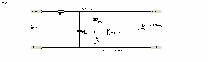
Figure 4.1 - Shunt Regulator
Shunt regulators used to be quite common, and they're still used in many circuits where 'perfect' regulation isn't needed. Dissipation is not a problem for low-current applications, but if you need a lot of current (or it varies widely) a shunt regulator is not the way to go. However, it is generally a fail-safe option, and that alone makes it useful. If the input voltage climbs to 50V (rather unlikely, but may be possible with some circuits), the resistor dissipation will increase to over 20W, and a 5W wirewound resistor will de-solder itself. All you need to add is a spring (I leave the details to the reader), and it becomes a home-made thermal switch. 
A zener can be used to activate a 'proper' protection scheme (using an SCR crowbar), but it's not a precision approach. Zener diodes always have some tolerance, and it's typically ±20%, although you can get 10% or 5% versions as well. A highly simplified circuit such as that shown next will work, but can never be precise, even with a close-tolerance zener diode. The issue with an over-simplified design is that there's no way to account for thermal effects (hot semiconductors conduct at a lower voltage than when cold), and there's so sensible way to make it adjustable. As shown, the circuit is designed for use with a 5V supply, with the circuit drawing no more than around 100-200mA. At higher current, the fuse will have measurable resistance (the voltage drop of a 1A fuse at rated current is typically about 200mV). More information about fuse characteristics is available in the article 'How to Apply Circuit Protective Devices'.
In the following circuit, a TRIAC is shown as an alternative, with the BT139 being able to handle a 10ms pulse of 145A. If you have positive and negative supplies TRIACs can be used, since they allow you to use the same circuit topology for both polarities. Note that MT1 and MT2 are not interchangeable. The trigger voltage must be applied between the gate and MT1, but the gate and MT2 voltage can be positive or negative with respect to MT1. For optimum triggering, the polarity of the gate and MT2 should be the same. The BT139 is only a suggestion, as it can handle up to 600V and it's inexpensive (less than AU$2.00 from some suppliers). The TRIAC can be used in the other circuits shown as well, but I've not included it to keep the circuits simple.

Figure 4.2 - Simplified 5V Protection Circuit
In theory, the circuit shown above will trip if the input voltage exceeds about 5.7V. The SCR will turn on, and the fuse will blow and/ or the supply's output will be shorted. However, temperature will play a big part here, because of the SCR's gate voltage. At 25°C, it will conduct with a gate voltage of about 1V, but this falls to around 800mV at 50°C. If the SCR were to get hot (because it's next to a high power resistor for example), then the circuit will trip with 5.5V input - assuming the zener voltage is exactly 4.7V and the SCR is 'typical'. There are too many assumptions and not enough certainty for this to be considered a precision approach. However, it's a lot better than nothing.
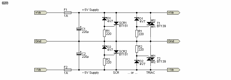
Figure 4.3 - Simplified ±5V Protection Circuit (Dual Polarity)
A dual polarity version is shown above, using either SCRs or TRIACs as switches. TRIACs allow the circuit to be fully symmetrical, but there's no particular advantage. The two switches (positive and negative) are identical with dual SCRs, maintaining the same polarities. It may look a bit weird, but the function isn't changed. Be warned that all of the simplified circuits only shut down the faulty supply, so if the positive voltage causes its circuit to operate, the negative supply will continue to work normally. This can cause circuits to misbehave (large DC offsets for example), so it's not a panacea. Shutting down both supplies (regardless of which one fails) is preferable, but harder to achieve.
Ideally we need something that can be varied to a precise trip voltage. It can then be tested, adjusted and verified (using a variable lab supply) before it's put to use. Needless to say, the solution becomes more complex, but it only needs cheap parts (certainly cheaper than the circuit being protected) and can be built as a small module, ready to be installed anywhere that you'd like to protect a sensitive circuit. The circuit itself needs to be flexible enough that it can be used with different supply voltages, but that becomes difficult with some ICs that use a 3.3V (and some even lower) supply. To protect these, you're almost certainly going to need a dedicated IC, or a more complex circuit with a separate supply.
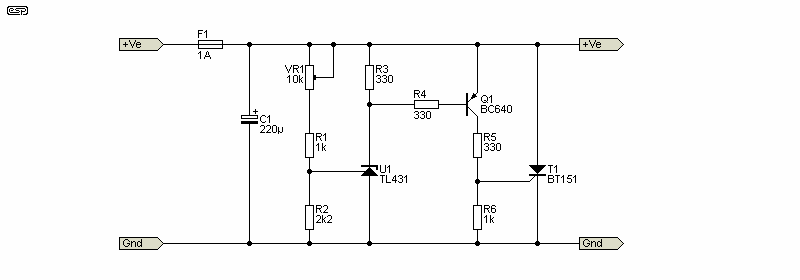
Figure 4.4 - Adjustable Protection Circuit
Now we have a circuit that can be set to a precise voltage, using the TL431 adjustable voltage reference. It doesn't rely on any semiconductor junction variations, whether from unit to unit or with temperature. It can be adjusted from 3.7V up to 15.1V as shown, but the range can be modified by changing the value of R2. Increasing the value means it will respond to lower voltages and vice versa. This general idea is not at all new - it's been around in various forms for many years.
Many other schemes can be found if you search, but many are poorly thought out and have potentially fatal flaws. The circuit shown in Figure 4.4 can be made more complex by using a comparator, which may provide a theoretical advantage, but no actual improvement. The circuit has to be fast-acting, even though over-voltage faults are usually not especially fast. The more parts that are used, the longer it takes ( typically measured in microseconds) for the protection circuit to react. An SCR is very fast - once triggered, the transition to full conduction takes almost no time at all. The BT151 (for example) has a turn-on current rise of 50A/µs, meaning that once triggered, the current will be 50A after just 1µs (assuming that the supply can even deliver that much current). Reality is different of course, but I measured a C122D SCR, and it took only 5µs to reduce 7V to 0.5V at low current (SCRs tend to get faster as current is increased).
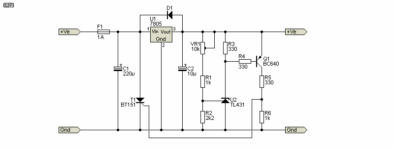
Figure 4.5 - Regulator With Over-Voltage Protection
In the Figure 4.5 circuit, if the regulator (U1) should fail, the protection circuit will operate and remove the input supply. The diode across the regulator is to protect it against reverse voltage during testing, but I suggest that the diode always be used. The protection circuitry should be adjusted and tested with the SCR connected to the supply via a resistor (choose a value that will provide about ½A), and once it's been tested and verified, the resistor is replaced by a link. The circuit will do nothing until there's a fault and it then short-circuits the incoming supply. This may never happen of course, but if the regulator fails and you have no protection, it could be a very expensive failure. There's no need to worry about the voltage drop across the fuse, so a lower value can be used if the protected circuitry doesn't draw much current. The same arrangement can be used for any current (and any regulator) with the only change being the voltage setting.
In most cases, the protection circuit needs to operate as quickly as possible. Depending on the circuitry being protected, there may be a possibility of very narrow 'spike' voltages that could conceivably trigger the protection circuit (false triggering). If this is a possibility then the circuit may need to be slowed down, or add a TVS and/or a big capacitor (about 1,000µF) in parallel with the output. If needed, the response time can be increased by adding a small capacitor between the base and collector of Q1. With the values shown, a 1nF cap between base and collector will add a 1.3µs delay. Increase the value to increase the delay (e.g. 10nF gives a delay of ~4.5µs). It's important to have as little delay as possible, as this provides maximum protection.
Most protection circuits will be used with relatively low voltages, and they will almost always be regulated. Using over-voltage protection with an unregulated supply is generally not necessary. By nature, unregulated supplies vary their output voltage depending on the load current and mains voltage. Since the mains can change by ±10% (and sometimes more), any protection scheme has to consider that, and any circuit that uses an unregulated supply will (or should) be designed to handle normal variations without failure. This is a topic unto itself, and is not relevant here.
Any solution using a variable voltage reference needs to account for the emitter-base junction of the trigger transistor. The reference voltage for the TL431 is 2.5V, and one must allow 700mV for the emitter-base voltage of the transistor. That means that the minimum voltage that can be detected is 3.2V, but it would not be prudent to try to use that. There's simply insufficient 'headroom' and no safety margin. This is where dedicated ICs come into their own, as they are designed to work with all common supply voltages.
Where voltages and currents are appropriate, you may be able to use a 'Polyswitch™' PTC thermistor in place of the fuse. These will provide protection, but don't need to be replaced if the SCR is turned on by an over-voltage. This can be handy, but you're relying of it acting every time power is turned off and on again. A blown fuse is a sure indicator that something is seriously wrong, but it's of limited use if the faulty power supply can't provide enough current to ensure that the fuse opens. Given that this is circuitry that may never operate for the life of the equipment, keeping the cost as low as possible is advisable. You also need to consider the internal resistance of PTC thermistors, which can be up to double that of a similarly rated fuse.
There are countless ICs designed to provide protection for sensitive electronics. These are often referred to as 'supervisory' circuits, because they can monitor several voltages and provide a 'power good' signal when all monitored supplies are within the limits defined by external resistors or internal software. Many don't have the ability to activate a crowbar protection system, although it can be cobbled together with some devices. Others have no provision to actually do something proactive if the supplies are out-of-bounds, other than provide a signal to the power supply to turn off. A supply with a fault may not be able to do so, and there can still be enough stored energy (in filter/ storage capacitors) to cause damage.
Because there are so many different ICs designed for power monitoring, it's not sensible to even try to cover them all, so this section is largely 'commentary' to advise the reader of the existence of such devices. The search and selection depends on too many criteria that are specific to an application. However (and purely as an example), I've shown a circuit for reverse polarity, under-voltage and over-voltage below. This is based on the LTC4365 datasheet, and in this instance it's intended for automotive applications.
To be able to use N-Channel MOSFETs as the switching devices, the LTC4356 uses an internal charge-pump supply to drive the gates, with up to 9.8V available at 20µA. With an operating range from 2.5V to 34V and a protection range of -40V to +60V, it's designed to cover a very wide range of potential uses. Naturally, it's only available in SMD packages (two different packages are made, but they're not pin-compatible). This is why pin numbers aren't shown in the drawing.
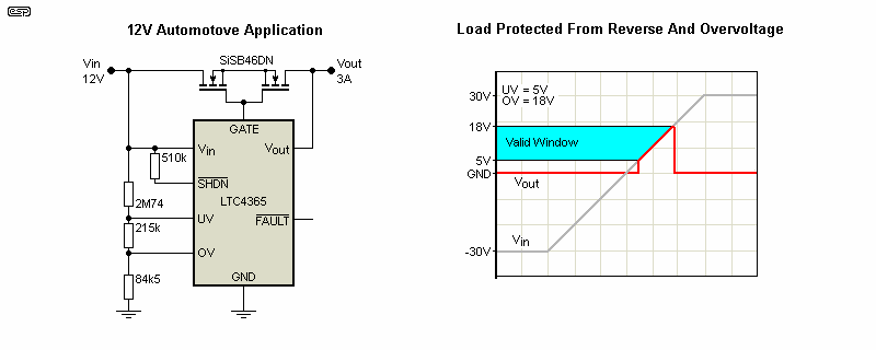
Figure 5.1 - Automotive Under/ Over/ Reverse Voltage Protection Using An LTC4356
The datasheet has many examples of different circuits, and if you wish to know more then download it from the link [ 5 ] below. The parameters are programmed by using resistors, and the arrangement shown (with two MOSFETs) is only needed if reverse polarity protection is required. A single MOSFET is enough to provide simple under and over-voltage protection. There's always a problem with this approach, because the resistors will often be inconvenient (i.e. unobtainable) values, so will usually end up being series or parallel devices to get the resistance needed. Of course you can also use trimpots, but they will take time to set properly in a production item, and also give the end-user something to fiddle with if so inclined. This rarely ends well.
As already noted, this device is one of a great many, and its suitability has to be verified for the needs of the designer. There can still be situations where the circuit malfunctions, or one (or both) MOSFETs become shorted due to an overload or high-energy transient of either polarity. All protective circuitry involves compromise, and building something that can handle all unexpected events is difficult, in part because some 'events' are unexpected, and no one would normally anticipate them. Unfortunately, life is full of 'unexpected events', as the recent COVID-19 pandemic has demonstrated only too well.
In some cases, the designers have already thought of things that the user may not have considered. For example, just a 300mm length of wire has a parasitic inductance of about 300nH, and that can cause ringing with fast transients. In such cases, use a TVS diode or other fast-acting means of damping transient ringing, which can cause under- and over-voltages that are too short to activate the protection circuit, but they can still cause damage!
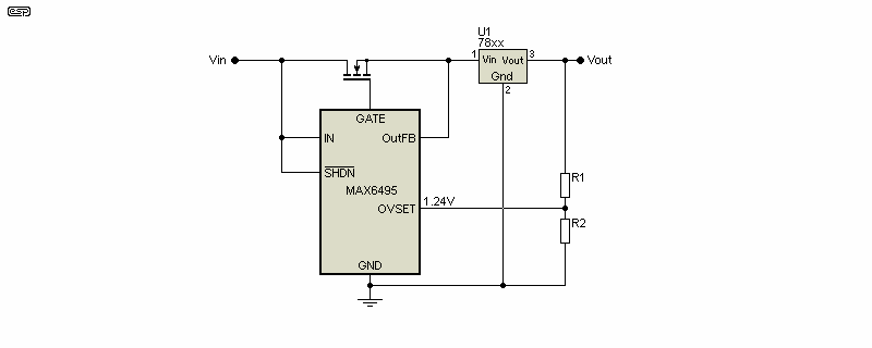
Figure 5.2 - MAX6495 Overvoltage Protection With Regulator
The MAX6499 IC operates almost identically to the LTC4356, but doesn't have reverse polarity protection circuitry. There's another IC in the same 'family' that does though - The MAX6496, which uses an N-Channel MOSFET for overvoltage and a P-Channel MOSFET for reverse polarity protection. For many applications (e.g. those that are permanently wired internally), reverse polarity protection isn't needed, so the circuit is simplified. The basic application circuit is very similar to that shown above. It's easier to program with the resistors, but it's only available in a TDFN package that's hard to work with. The MAX64xx devices can operate at up to 72V.
The MAX6495 can monitor the output of a regulator, either a DC-DC converter or linear. If the voltage at the 'OVSET' pin exceeds 1.24V the IC turns off the MOSFET. However, the circuit shown is an over-simplification, because it will turn on and off if the regulator fails. To be useful, you'd need to incorporate a latch so that once triggered, it cannot restart. Note that the circuit shown is adapted directly from the datasheet, which doesn't offer a suggestion as to how to prevent it from turning on and off for as long as the fault continues. It is claimed that the IC will enter a 'linear' mode to maintain the output at the OVSET level, but this can only protect against transient events and long-term operation will cause the MOSFET to overheat and probably fail.
In addition to specialised devices, many Class-D amplifier ICs also include under- and over-voltage detection. This prevents erratic operation at low voltages, and protects the IC and output MOSFETs from over-voltages that Class-D amps can develop due to a phenomenon known as 'bus pumping'. (An explanation of bus pumping is outside the scope of this article.)
I imagine that some readers will wonder why anyone would bother to detect under-voltage conditions. It's tempting to think that if the voltage is too low, nothing 'bad' can happen. Unfortunately, this isn't the case at all, and even some otherwise well-behaved circuits can malfunction if the voltage is too low. One example (and it's directly related to audio) is opamps. There are several common opamps that misbehave quite badly if the voltage is less than their rated minimum voltage. The TL07x series is an example, where they either make 'odd' noises as the voltage falls below the threshold (which is around ±4V but it varies) or show very high output offset voltages that can cause loud 'thumps' through the speaker (via a power amplifier of course). The Project 05 power supply was designed to include a muting circuit for this very reason.
Other devices that can (and do) misbehave include switchmode power supplies. The controller IC almost always includes a facility to detect an under-voltage condition and prevent the supply from functioning. There is one IC that I know of that does not include this - the XL6009 boost converter IC, which is supposedly an 'equivalent' to the LM2577. The latter has in-built under-voltage protection, where the XL6009 does not. As a result, at low input voltage the boosted output voltage is uncontrolled, and can reach 40V with an input voltage of 3V. The datasheet claims that it has under-voltage protection, but it doesn't work. There are undoubtedly other examples, but the ones mentioned are those I have experienced first-hand.
In general, under-voltage cutouts are used anywhere that a circuit might malfunction or misbehave once the supply voltage falls below a minimum, determined by the circuitry involved. It's usually much less of a problem than over-voltage, as it's unlikely to cause any damage to the circuitry. The switchmode boost converter referred to above is a rare exception. Most designers don't bother unless they know that the circuits will do something 'bad'. Most circuits just stop working if the voltage is too low.
An exception to the 'they just stop working' idea is an electric motor. Whether AC or DC (including many 'brushless' DC motors), if these are powered under load when the supply voltage is too low, they may not be able to start, and that causes very high current flow with no cooling (many motors rely on an internal fan to force air past the windings). With these, an under-voltage protection circuit should be considered essential if there's a likelihood that the supply voltage may fall to a level that's insufficient for the motor to run normally. It's not a common problem, but it certainly exists, and can cause expensive damage.
One is faced with a conundrum with any under-voltage cutoff system. To be able to function, the cutoff circuitry must be able to work at the lowest likely voltage, but be able to handle the 'normal' full voltage equally well. The circuit doesn't have to be functional with zero volts input for obvious reasons, but (depending on the nature of the load) it may need to work with less than 5V input. It should also cause no voltage drop of its own, as that would reduce the voltage to your circuitry (or motor) all the time, and it may be subject to high dissipation when powering the load.
This is a place where a relay can be useful, as they have low contact resistance and dissipate very little power. However, there's a trap! Let's assume that you use a 5V relay with a 10A contact rating, and suitable for up to 30V DC switching. There are countless candidates, and most will be very similar to each other so I'm using 'generalised' data. A 5V coil relay will typically activate with around 3.5V across the coil, so if your circuit operates from 5V, the relay alone will prevent power being delivered to the circuit unless there is at least 3.5V available.
However (and here's the trap), the relay will continue to provide power until the coil voltage falls below the 'drop-out' voltage, which can be as low as 500mV. A 12V relay will pick up at around 8.5V, but won't release until the coil voltage falls below 1.2V. The drop-out voltage is far too low if the supply voltage falls after the relay has engaged. An example might be an automotive application, where the battery voltage is sufficient to allow the relay to activate, but falls as soon as any significant current is drawn (an almost flat battery or a high-resistance battery connection will do just that). The relay may not release under these conditions, so additional circuitry is essential to force the relay to release if the voltage is lower than your device can tolerate.
Figure 6.1 - Automotive Under-Voltage Protection Using A Relay
Figure 6.1 shows one way this can be done. The input voltage must be greater than 10.6V (nominal) for the relay to activate, and if it falls below 10.6V at any time Q1 turns off and so does the relay. This circuit is the simplest way to achieve the result, but it has a built-in flaw! If you attempt to power your circuit (let's assume a motor) and that causes the voltage to fall, the relay will drop out. With no current drawn from the battery, the voltage will rise again, and the relay will re-engage. The connected load will cause the voltage to fall again, and the cycle will continue.
C1 provides a small delay to prevent the relay from behaving like a buzzer, but a better solution would be to use a low-voltage opamp or comparator to provide hysteresis and a timed 'lockout' period (at least one second). All problems have a solution, but it's not always obvious, and a seemingly trivial exercise can become complex very quickly. There is always a cost-benefit formula to be satisfied, and this is especially true for commercial products. For example, no car maker will include anything that's not strictly necessary, so don't expect to find circuits such as the above for each motor in your car. It would be 'nice' if they did so, but most modern vehicles have many motors, and the cost would be prohibitive. In most cases, there's no real benefit either, but your specific application may be very different.
This is especially true if a motor is turned on remotely, where there's no one around to verify that it's working. Systems using microcontrollers or similar should have the necessary protection built into the code, with a routine to verify that the motor's supply is 'good', and/ or to monitor abnormal operation.
There's another class of under-voltage detection and disconnection circuit, namely battery protection. Whether it's a single cell (e.g. Li-Ion) or a complete battery (a collection of cells in series, parallel or series-parallel, any chemistry), most battery types will be damaged if discharged below a specific voltage. This varies with different battery chemistries, and for Li-Ion it's about 3V/ cell, or 1.8V/ cell for lead-acid cells (open-circuit voltage). Ni-MH (nickel-metal hydride) cells should not be discharged below 1.0-1.1V per cell. Recommendations vary, so you must do your own research.
There are countless ICs for protection and balance-charging for Li-Ion cells and batteries, and some include under-voltage (or over-discharge) protection. It's always tricky with batteries, because the under-voltage protection circuitry will consume some power, and that can cause the battery to be discharged even after the load is disconnected. Project 184 shows how I got around that limitation, by disconnecting both the load and the under-voltage cutoff circuit from the battery if the voltage falls below the minimum. The circuit is turned on by the act of connecting the battery. An ultra-low power version of the circuit is shown below. It draws only ~700µA in use (excluding the load). The LM285LP-2-5 regulator IC will regulate down to 10µA cathode current.
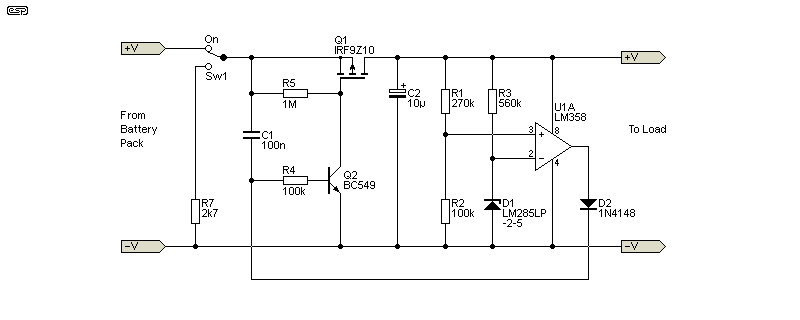
Figure 7.1 - Battery Cutoff Circuit (From Project 184)
There are many requirements for this kind of circuit. Nearly all battery chemistries are 'upset' by over-discharge, so a means for prevention is essential. Any piece of test equipment or other gear that uses a rechargeable battery should incorporate an under-voltage cutoff to prevent battery damage. It needs to be designed so that the protection circuit itself doesn't cause further discharge, either by disconnecting itself, or by using ultra-low power consumption electronics. The allowable 'parasitic' discharge depends on the application, the battery size (in Amp/ hours) and the likelihood (or otherwise) of the battery being left discharged for a long period. There is no 'one size fits all' solution. As is to be expected, the Net has countless examples, but not all are satisfactory. There are quite a few options that allow an entire cutoff circuit to work with a supply current of less than 200µA, but it does require some trick circuitry to work with such a low current. The circuit shown above is a good option, but an even lower-power single opamp would reduce current even further.
CMOS opamps are potentially a good choice, but most are rated for a maximum supply voltage of 5.5V (5V recommended). This means that the opamp's supply has to be regulated as well, which complicates the design. Very few applications require that the under-voltage cutout circuit should draw less than 1mA, unless the connected circuitry is also very low-power. A current draw of even 10mA for the cutout is of little consequence if the circuit draws 100mA or more. 10mA would be silly if the connected circuit only draws 2mA, so the design has to be adapted to the application.
Keeping protection circuit operating current to the minimum has several advantages. One is that the circuit itself doesn't draw a current that reduces battery life, and the other is to ensure that the circuit doesn't continue to discharge the battery after a forced disconnection of the load. This is particularly important for equipment that may sit around for extended periods without being used, as even 100µA will eventually discharge a battery or cell to zero volts. It may take a long time, but when combined with self-discharge (a common 'feature' of most battery types) it will eventually cause over-discharge damage.
Great care is necessary if the application is 'mission critical' (a battery-powered drone or other aircraft for example), and you usually have to accept the possibility of over-discharge to prevent your aircraft from falling from the sky when the voltage falls below the threshold. A damaged battery isn't cheap to replace, but it's a great deal cheaper than replacing the entire aircraft and its payload. In such cases, it's better to have a signal that warns you that the battery voltage is low so remedial action can be taken before the battery is damaged or the aircraft crashes. Further discussion of this is outside the scope of this article.
It's worth adding a short section on MOVs (aka voltage dependent resistors or just varistor), as they are commonly used in SMPS (switchmode power supplies) and for mains 'surge' protection in power boards and the like. A MOV can dissipate a prodigious amount of current for a short time, depending on the device used. 1kA (1,000A) or more is easy, but the duration has to be very short (20µs or less). Every time a MOV conducts, a small amount of the working material (typically zinc oxide) is damaged, and eventually the MOV will fail. The most common end-of-life failure mode is short-circuit, and the MOV will (literally) explode. In some cases a MOV will be paired with a thermal fuse that opens if the device gets hot - the precursor to complete failure.
There are MOVs with an internal thermal fuse, and some have an extra terminal to connect an indicator that shows that protection is still provided. The same thing can be done with an external thermal fuse, but it needs to be in close thermal contact with the MOV(s). While MOVs with an integrated thermal fuse are certainly a good idea, you must also consider replacement at some time in the future. Should the selected part become unavailable, your protection circuit can't be repaired. An external thermal fuse should be rated for no more than 150°C.
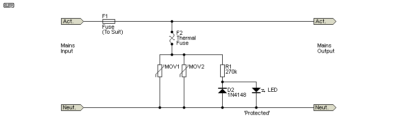
Figure 8.1 - MOV Overvoltage Protection With Indicator
The general idea is shown above. The thermal fuse would be mounted between the two MOVs, and in good thermal contact with both. The indicator should be a high-brightness LED, as the available current is less than 1mA with 230V mains. R1 must be rated for the full voltage, but in most cases you'd use two resistors in series to ensure safety. As long as the MOVs are intact and the thermal fuse hasn't opened, the LED will be 'on', indicating that all's well. The diode in parallel with the LED protects it against reverse voltage.
The MOVs, main fuse and thermal fuse all need to be selected for the mains voltage in use (230V or 120V AC), and everything has to be in an enclosure that prevents accidental contact. MOV selection is almost an art form, because not all manufacturers have the same recommendations for the voltage rating needed for the mains voltage. It's fairly common to use 275V AC rating for 230V mains, and around 150V for 120V mains. If in doubt, consult the datasheets, as these recommendations vary widely. Selection has been simplified (somewhat) recently, and you can often use a MOV that's rated for the mains supply voltage in use.
Specifying a voltage that's too low will cause premature failure of the MOV, so it's usually better to use one that has a higher voltage than will ever be experienced in normal use. For example, although Australia mains power is nominally 230V, it can (and does) occasionally exceed 260V. The same thing happens everywhere, and expecting any MOV to clamp a sustained voltage that exceeds its rating will fail prematurely.
Note that you may see references to MOVs being used between active (live), neutral and earth/ ground. In most countries this will not be permitted, and they should only be connected between active and neutral.
This article is a brief look at the world of 'supervisory' and protection circuits, designed to protect electronics against (predominantly) over-voltage conditions. This isn't an area that attracts too many readers, which is a shame, because there's a great deal to be learned from datasheets and other literature on the topic. One thing that's guaranteed in electronics is that there's always something new (even if it's only new to you) to be found, and by knowing about these techniques you are less likely to be left wondering what to do if you encounter a problem with a design.
As with any circuit, the implementation will determine whether it works or not. With IC designs, there are many tests necessary to ensure that the reference voltages are set correctly, and you must also consider component tolerances. No component is exact - IC internal reference voltages, resistor values and in some cases even PCB track resistance can affect the design, and everything has to be considered. This isn't quite so critical for a simple crowbar over-voltage protection circuit, but IC designs can be very fussy (look at some of the resistor values in Figure 5.1 as an example).
Make sure that tracks are sized appropriately if a crowbar circuit is used. I'm sure that most constructors would rather replace a fuse than have to repair a track that's been blown off the board. This can happen with very high currents, repairs can be difficult and always look messy afterwards.
Crowbar circuits are very robust and operate quickly - generally within a couple of microseconds. This can cause problems with some circuitry, so it's essential that you understand the circuit being protected, and add any necessary additional protective measures to ensure that a very sudden removal of power doesn't cause any problems. Be especially careful with 'downstream' regulators (e.g. from 5V to 3.3V), as they may not have an 'anti-parallel' diode as shown in Figure 3.1. The purpose of the diode is to ensure that no voltage (greater than 650mV) can exist at the output of a regulator when the input voltage is suddenly removed (or shorted out). Under normal operating conditions the diode is not usually necessary, but it becomes essential if a crowbar circuit is introduced.
Not every circuit needs protection, and the need has to be determined based on the allowable supply voltage range, the cost of the protected circuitry and the cost of protection. It would make no sense to use a $10 IC to protect a $5 circuit, and nor would it make sense to try to protect a $1,000 circuit with a 10 cent fuse. Power supplies (especially 'old school' linear [mains transformer based] types) are remarkably reliable, provided the regulator IC is provided with a heatsink as needed and everything is rated appropriately. Even most switchmode supplies are surprisingly reliable, but they won't last for 50 years or more (common for linear supplies). Given the expected life of many modern systems, many people seem to have accepted that a life span of 5 years is alright (I disagree, but that's another story).
Main IndexArticles Index