
|
|
| Elliott Sound Products | Project 184 |
 Main Index
Projects Index Main Index
Projects Index
|
With Li-Ion batteries now dominating the rechargeable market, using battery power for audio projects (especially test equipment) is a viable proposition. Unlike alkaline cells and batteries, they don't leak if left for too long, but they are very sensitive to the charging process. However, they also have high capacity in a relatively small volume and are ideal for many projects. Freedom from mains leads is particularly attractive, as that eliminates any possibility of ground loops. Note that I've used the term 'Li-Ion', but in general that also applies to lithium-ion polymer (Li-Po), with the most common difference being the casing used. Li-Ion cells are usually in a hard (often cylindrical) case, with Li-Po uses a soft (polymer) outer casing.
The disadvantage of Li-Ion batteries is that the charging requirements are more complex, because a balance charger is absolutely essential for a series battery pack. The alternative is to use 3 or 4 × 18650 cells (18mm diameter × 65mm long), which can be removed and charged in parallel. Chargers and 4-cell holders for these are readily available, and this eliminates the complexities encountered with series charging. With a typical capacity of around 3,500mA/H and with an example 50mA total current drain, you should get close to 70 hours of continuous use before re-charging is necessary. If 'protected' calls are used, there may be no need to add a voltage cutout, as the cells have this built-in. However, despite the same size nomenclature (18650), protected cells are usually closer to 70mm long, so the cell holder must be able to accommodate the extra length. Also, note that not all protected cells have an under-voltage cutout.
For information about charging Li-Ion cells and batteries, see the ESP article Lithium Cell Charging & Battery Management, as the charging regime must be followed closely to ensure safety (especially regarding the fire risk). A simple charger as used for 'ordinary' batteries cannot be used, because the voltage across each cell is critical to ensure that no cell is overcharged (4.2V is the maximum allowable for a Li-Ion cell).
The 'ideal' cutoff voltage depends on the material you read. It's variously stated to be 2.7V/ cell, 3V/ cell and 3.3V/ cell, and quite obviously they can't all be right. I've opted for 3.3V/ cell as I consider that to be a very safe voltage, but you may not get the full run-time from the battery [ 1 ]. However, you are also much less likely to damage it or reduce its capacity over time, so IMO the higher voltage is justified. One of the options shown below (Figure 5) lets you adjust the voltage for whatever you like, but I wouldn't be game to go any lower than 3V/ cell. If unsure, get the datasheet from the manufacturer of the cell(s) or battery, as that's likely to be real data, rather than supposition.
With three Li-Ion cells (a 3S battery), the total voltage is (nominally) 11.1V, which will happily drive most opamp based projects. Regulation is usually not necessary, because the output from the battery is generally very quiet, and that's the assumption made here. The voltage will vary over time, but that doesn't affect most circuits. In some cases, you may prefer a higher voltage, and you can easily get a total supply of 14.4V (four cell (4S) Li-Ion battery pack). It's easy to modify the circuit for other voltages (higher or lower).
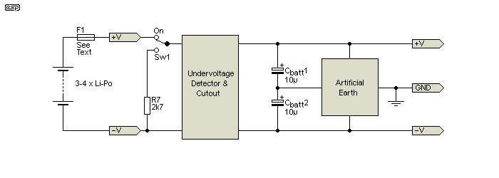
Figure 1 - Typical Connections With Battery Power Supply
The general scheme is shown above. Note that the fuse is not optional - it must be included, but it's not shown in the following drawings. The fuse rating will be selected to suit the load and the battery, and it ensures that an accidental short circuit won't damage your battery pack. Some include an over-current protector that may or may not be a resetting type. With no fuse, the battery may have to be discarded if a fault opens the protective circuit. R7 may look out of place, but it's included in all the following diagrams and the same designator has been used (the reason for it is described below).
Because most circuits require a dual supply, an 'artificial earth' will likely be required. This is easier to implement than a tapped battery, and allows any cell configuration from 3S (11.1V nominal) to six or more cells. All points in a project shown as earth/ ground connect to the 'artificial earth'. This is only a suggestion, but it means that most ESP circuits don't need any modification, although there are some that may require a gain reduction to prevent distortion (P06 for example).
The circuits shown here are designed to turn off when the minimum voltage is detected. Once off, the only way that the circuit can be re-started is to turn off the power switch and turn it back on. If the battery voltage has 'rebounded' (risen above the cutoff threshold) your circuit will operate for a short time, but will turn off again fairly quickly. This is as close to foolproof as you can get, especially since battery drain is zero when the circuit turns off (limited to the drain-source leakage current of the MOSFET).
An alternative circuit that remains connected to the battery is far simpler to implement, but it will continue to draw current after the external circuitry has been powered down. It's easy to keep it to less than 500µA, but that would still continue to drain the battery unless it's noticed fairly quickly. This was the first option I looked at, but it's not viable if total battery protection is required. A 3,500mA/H battery will be drained flat in about 700 hours. This assumes that 1/10th capacity remains when the voltage has fallen to 10V for a 3S battery. That's almost one month, but at the end of that period the battery will have been discharged to well below the minimum allowable voltage.
If current is kept to the absolute minimum (less than 10µA) this won't be an issue, but that means that the circuit must be high impedance throughout, meaning very high value resistors, and an ultra low power opamp and voltage reference. These parts are available, but not readily, only in surface mount (SMD) packages, and they aren't cheap. Overall, the technique shown here is a far better option, using only common, low-cost parts throughout.
None of this circuitry is needed if the powered circuit uses a micro controller, because the micro can monitor the battery voltage, and an on-off push-button can be used to provide power initially. The micro then looks at the battery voltage (using an ADC), and if it's above the minimum turn the circuit on. A second button press is decoded by the micro and turns the circuit off again. While operating, the ADC checks the voltage at regular intervals and turns off the entire circuit (optionally after saving any data collected or other 'housekeeping' tasks needed). While push-on/ push-off buttons can also be used with analogue circuits, it's more difficult to implement and requires some logic circuitry. This option is not included here.
For a completely analogue circuit, a simple toggle switch is an easier (and cheaper) option for the power switch, and the circuit shown here needs a 'kick-start' before it will turn on. Without C1, applying power via the switch would do nothing, because the MOSFET will not pass any current so the circuit never gets the power it needs to operate. The kick starter only needs to ensure power is available for a few milliseconds, after which the MOSFET is turned on via the comparator and power is delivered normally. Should the battery voltage be below the minimum, the circuit will provide power for about 20ms, and will promptly turn off again.
Another option that's common in battery operated test equipment is to use a timer. As long as you are still using the device (as determined by changing ranges, etc.) it remains on, but turns off after a predetermined time with no 'activity'. This technique can be achieved using variations of the circuit described, but there's no easy way to detect that anything has changed so it's not really applicable. If there is sufficient interest, this is an option that may be covered in a future project.
Note that no PCB is available for this project, but if there's enough interest one may be offered. It's a very versatile circuit and can be adapted to any battery chemistry, so it should have wide appeal for any number of battery powered projects.
One of the major challenges with battery power is to ensure that the battery is not run flat if you forget to turn off the power. This will damage Li-Ion (and most other) batteries, and depending on the level of discharge they may not recover. Suitable circuits are few and far between, and there are some special precautions that need to be taken to ensure that the shutdown circuit doesn't flatten the batteries by itself. While 'protected' cells (or batteries) do exist, they have additional circuitry that may or may not include an under-voltage cutoff. Specifications are often very unclear on this (and other) details, and it's better not to rely on a circuit that may not work as intended.
The circuits that follow are designed to disconnect the battery when the voltage falls below 10V (for a 3-cell battery). This is generally considered to be a safe voltage (3.3V/ cell), and anything lower is used at your risk. While 10V is (IMO) pretty close to ideal, it's not uncommon to discharge cells to 3V, and sometimes even less is suggested. The circuit doesn't need any fancy on/ off switching - a normal toggle switch or similar is all that's required. Ideally, the detector will be adjustable, and a trimpot (as shown further below) is highly recommended. With the trimpot set for a total resistance of 10k (including the series resistor R2), the cutout voltage is almost exactly 10 volts. A resistor change for 9V (3V/ cell) is also shown.
When the voltage falls below the threshold (set by the zener diode and R1/ R2 voltage divider), the circuit turns off completely, with the only current drawn being a tiny leakage current through the MOSFET. So it can turn on, it needs a 'kick-start', which is provided by C1. This cap passes enough current to turn on Q2, which in turn cause the MOSFET (Q2) to conduct, providing power to the rest of the circuit (and your electronics of course).
Note the wiring of the switch! This is important, and if you get it wrong you may end up with 2.7k across the battery permanently. Without this 'unusual' wiring, C1 cannot discharge and you won't be able to turn the supply on again after it's been turned off. The switch is arranged to ensure that C1 has a discharge path when Sw1 is turned off. Please be very careful when you wire the switch, as a mistake could be dangerous. There is a fuse in the battery line so there is some protection if the circuit is badly miswired. Ensure that the circuit (including the switch) is tested thoroughly (see 'Circuit Testing' below) before you connect the battery.
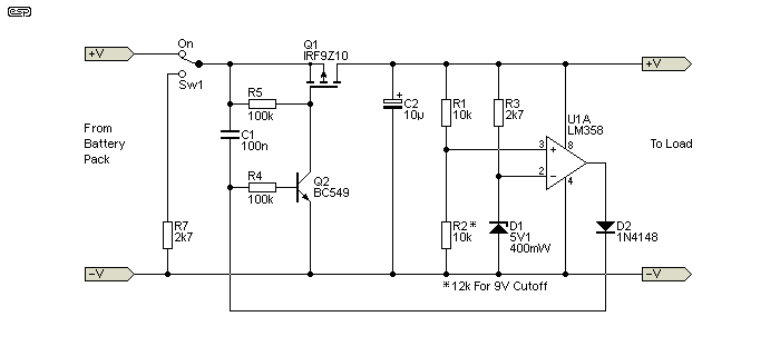
Figure 2 - Battery Power Supply Under-Voltage Detector
Q1 is a P-Channel MOSFET (e.g. IRF9Z10 aka SiHF9Z10 as shown), and is switched by Q2, any suitable NPN transistor. D1 is a 5.1V zener diode, and it sets the reference voltage for the comparator (U1A). This is one half of an LM358 or similar, chosen for its very low power consumption, near zero volt output capability and price - this is a very cheap opamp but it's ideal for the purpose. It's important that the circuit consumes very little power itself, so some resistances are higher than you'd normally expect to see. With a supply current of only 500µA for U1 and only a couple of milliamps for the remainder of the circuit, any decent sized battery should barely notice the difference unless your circuitry is also very low power. The circuit as shown is suitable for electronics that draw up to around 1-2A, limited by the 'on' resistance of the MOSFET. For lower current, R5 can be increased up to 1MΩ to minimise the current through Q2. If R2 is 12k the cutout operates at 9V (3V/ cell). This option is also shown for the other variants.
The voltage reference is the most irksome part of the circuit, because it must draw some current to function. Precision reference 'diodes' (they are actually integrated circuits) are one way, but the simple zener is cheap, reliable, and will generally work well even at fairly low current. Without a reference voltage, the circuit has no way to monitor the battery voltage because there's nothing to compare it with. Zener diodes aren't generally used with sub-milliamp current, and this was tested thoroughly and the results were as I expected. However, at a current above 1.5mA, the zener voltage is stable enough to be usable with a 400mW zener, and the values shown provide around 1.85mA at the turn-off voltage. Do not use a higher powered zener diode, because its voltage will be too low and unstable at the low current provided. The voltage is still lower than the rated value due to the reduced current, but overall the zener is more than satisfactory for the purpose. The 1.85mA zener current isn't a problem unless you have a specific need for very low current drain.
If you're not enthusiastic about using a zener diode, you can use a reference diode (typically 1.25V or 2.5V), but that requires either that the voltage divider is changed or you add 'programming' resistors. A reference 'diode' such as the TL431 can be used directly, or with a programming voltage divider to set the voltage to 5V or some other voltage as you might deem appropriate. While this does add extra parts, some constructors may find it a useful modification. Consider that these reference voltage ICs generally need between 600μA to 1mA minimum current to operate properly, so the current saving isn't great, especially when the programming resistors are added. You could us an LT1461, but it's SMD, and at almost AU$10 each (for the cheapest version) I suspect that most constructors will steer clear of it.
When the circuit detects that the battery voltage has dropped below the minimum you've set, current drain falls to zero. Only the leakage current of the MOSFET and PCB remain, and they should be negligible even if the circuit is built on Veroboard. C1 is shown as 100nF, but depending on your circuit it may need to be a higher value. This is especially true if you've used large electrolytic bypass caps, because they will take longer to charge via the MOSFET. C1 must be able to keep the circuit turned on until the output voltage has risen to above the threshold (10V as shown above).
C1 is the 'kick-starter' to power the circuit when the switch is turned on. If there's a significant bypass capacitor (more than 220µF), C1 may need to be increased in value. Once power is available, the opamp (wired as a comparator) provides base current to Q1 and keeps Q2 (P-Channel MOSFET) turned on. Provided the +ve input remains more positive than the -ve input of U1A, the opamp's output remains high, keeping power on to the circuit. The voltage at the inverting input of U1A is maintained at 5V by the zener. When the voltage at the non-inverting input is above 5V, the output of U1A remains high and power is available. When that voltage drops below 5V (ignoring input offset which is a mew millivolts at most), the output falls low and disconnects the power completely.
R7 is included to ensure that C1 is discharged when the switch is turned off. If R7 were not included, C1 could retain a charge so the circuit will fail to turn on again if switched on-off-on fairly quickly. As shown, C1 will be almost fully discharged within about 50ms when the switch is turned off. This should be fast enough for all normal usage. If C1 is increased in value, R7 may need to be reduced by the same ratio. It's certainly possible to discharge C1 without the extra connection to Sw1, but it adds more parts and is hard to justify.
If you use a bipolar transistor instead of the MOSFET, you must include a resistor in series with the collector of Q2 to limit the current. Expect the circuit to draw up to 5mA, depending on the base current of the transistor switch. This is of little consequence if your circuit draws around 50mA or so, but if the current is less the base current can be reduced accordingly. The collector resistor (R6) needs to pass about 1/50th of the load current, so for 50mA you need 1mA base current. This assumes that the transistor is a low-current, high gain type (such as a BC559B/C or equivalent). For more than 50mA, a MOSFET is the better choice.
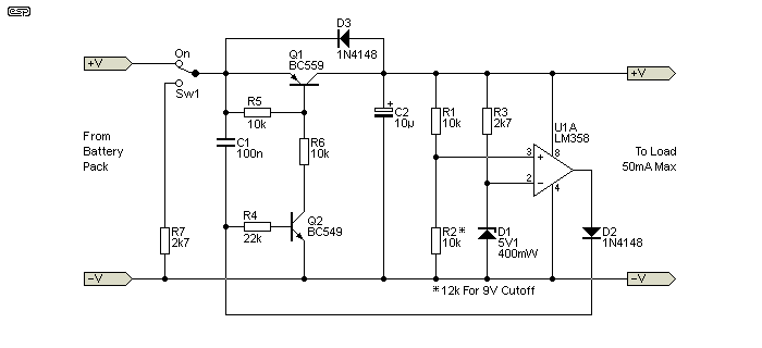
Figure 3 - Battery Power Supply Under-Voltage Detector Using BJT
A PNP transistor is fine for low current operation, and is more likely to be found in your parts collection than a P-Channel MOSFET. Circuit operation is identical, but D3 has to be included (1N4148 or similar diode) so the BJT isn't reverse biased due to external capacitance (in the 'artificial earth' or external powered circuit). Without this extra diode (which exists by default in a MOSFET), Q1 would be reverse biased and may be damaged when the circuit turns off (or is turned off with the switch). The added cost is still far less than a MOSFET and the diode isn't a great impost on PCB space.
This is the circuit I built for my own use, because I have plenty of BJTs but no low power P-Channel MOSFETs in my parts drawers. With no parts selections (close tolerance resistors, etc.) the cutout voltage is 9.85V, which is perfectly alright. I know that a lower voltage still is ok, but for this I prefer to err on the side of caution. There are several changes you can make to the circuit, and these are described next.
This unit is now installed in my low noise test preamplifier (see Project 158), and it works perfectly. Indeed, it was this very project that inspired the circuits shown, after I accidentally left the unit turned on and discharged the battery to well below the recommended voltage. Since these batteries are not inexpensive, I needed a way to ensure that it never happens again. It works exactly as described here, and now I know that even if I forget to turn it off, no battery damage will occur.
There are several options for most of the parts shown. Instead of an LM358 you could use a TLC3702 dual comparator (much lower supply current, but more expensive and limited supply voltage). The opamp (or comparator) used must be capable of taking its output voltage to zero volts. You cannot use a TL072 for example, because it draws too much supply current, and the output can't drop below around 2V above the negative supply. There are quite a few suitable opamps, but the LM358 suggested is low power, low cost, and has all the features needed.
The MOSFET is selected for the output current required, and the IRF9Z10 (SiHF9Z10) suggested is a 60V, 6.7A device with an 'on' resistance of 0.5 ohm, and is good for up to 1A or so). For low current (less than 50mA) you can use a PNP transistor. The overall current draw will be a little higher because a BJT needs base current, but you won't need very much (for example, 1mA is more than enough for a 50mA load). As noted above, a precision voltage reference can be used instead of the zener, with a corresponding change to the voltage divider that sets the cutoff voltage.
None of the circuitry is critical, so you can experiment with most of the parts to get the results you need. You do need to be able to work out the resistor values to get everything to function properly, and in particular to set the cutoff voltage accurately. Instead of the LM358 opamp, an LM10 can be used - this is an opamp with an in-built precision reference, so it will save the zener diode and one resistor. However, it's a more expensive part than the LM358 (by a significant margin), and you don't get the extra opamp to use as part of the artificial earth.
You can also increase the values shown for the voltage divider (R1, R2 and VR1 if used) to reduce current, but R3 needs to supply at least 1.5mA to the zener and can only be increased if the voltage is greater (more cells in the battery). For example, if your battery pack uses four cells (14.8V nominal, 13.3V cutoff), R3 can be increased to 5.6k. Overall, the current drawn by the cutoff circuit will typically be a small fraction of that drawn by your circuit, and the additional drain will have minimal effect on battery life before a recharge is needed.
The schematics shown will all work without any changes, but the circuits can also be looked at as a design idea, so you can make changes as required provided you verify that it still functions as intended. One change that will reduce current is to increase the value of R4. I've shown a value of 22k, but that can be increased to 100k if preferred. The difference is about 350µA, which is worthwhile if your circuit is low power.
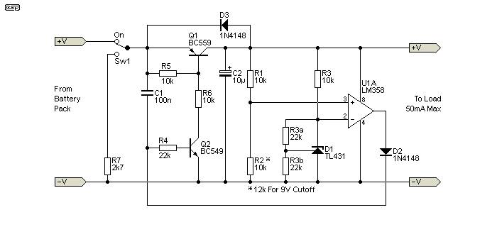
Figure 4 - Under-Voltage Cutout Using TL431 Voltage Reference (Based On Fig. 3)
If the TL431 is used, the reference current can be reduced, lowering the circuit's total current drain. The minimum current specified for the TL431 is 400µA, and the reference pin current is about 1.5µA so the 22k resistors shown will be fine. To reduce it further, the voltage divider (R1 & R2) can use higher value resistors, and the collector load (on Q2) can be increased. It's unlikely that you'll be able to get the total current below 2mA with a BJT for Q1, but it should be easy enough with a MOSFET. In that case, R4 can be increased to 100k (reducing C1 would be a good idea too), and R1, R2 could also be 100k, but you'll have to test the cutout voltage carefully with such high values. The minimum current drain possible is probably around 1.5mA, and anything less would require excessive resistance values.
Probably the most common variation needed will be to obtain more output current. The circuit can drive any P-Channel MOSFET, so there is (theoretically) almost no limit to the current the circuit can provide. One candidate for higher current is the IRF9140, rated for 100V and 21A, however a safe maximum current is around 5A due to the 0.2Ω 'on' resistance. P-Channel MOSFETs are almost invariably worse than N-Channel devices in this respect. This also means that power dissipation is higher and output voltage is reduced. The STP80PF55 would be a good choice, rated for 55V, 80A and an 0.018 ohm on resistance. Output current up to 15A would keep dissipation down to about 4W.
There are some essential changes though, because R5 is too high in value to ensure that a large MOSFET turns off quickly. With an output current of 10A, the MOSFET will dissipate up to 50W as it turns off, and this period should be as short as practicable. If R5 is reduced to 2.7k, MOSFET turn-off will be fast enough to keep the dissipation to a minimum. In turn, that means that the value of R4 may have to be reduced to ensure that Q2 can turn on fully.
You will also need to add a resistor and zener to protect the gate of the MOSFET if the battery voltage is more than 15V. Simply include R6 - you will need to calculate the value based on the value of R5 and the maximum permissible voltage for the MOSFET's gate-source junction. The zener diode acts as a 'backup' to protect the gate, but the gate voltage determined by R5 and R6 should be less than the zener voltage. The MOSFET will most likely need a heatsink if the current is high, and that's something I leave to the constructor. If you are playing around with high current Li-Ion packs, then it's expected that you have sufficient knowledge to be able to make the required calculations.
For medium current duty (up to 1A or so), Q1 can be a Darlington transistor rather than a MOSFET. There is a small voltage drop across any Darlington transistor, and you need to factor that in when the cutout voltage is set. Depending on the current, the cutout voltage needs to be set to about 0.75V less than normal, because the battery voltage will be higher by the same amount. While you do lose a bit of voltage, the circuit's current draw is also reduced because so little base current is needed for a Darlington transistor. You can use either a discrete or 'packaged' Darlington, depending on what's readily available.
Where particularly high current is needed, the MOSFET can be replaced by a relay. Even very ordinary relays can handle 10A with close to zero contact loss, but the coil current is quite high so there is a much greater current drain. If your circuit draws 10A from the battery, you probably won't be too concerned about an extra 50mA for a relay coil. This option isn't shown, but it's not difficult to change the circuit to suit. Note that the power switch also to handle the output current, so this must also be considered. A diode must be included in parallel with the relay coil.
If you like the idea of using on and off push-buttons, simply use one button in place of C1 (on), and another from the base of Q2 to the negative rail (off). Because the switch is then eliminated, this may be a better choice for high current applications because the mechanical push-button switches only handle minimal current (a few milliamps at most).
The circuits shown above assume a 3-cell battery (11.1V), but are easily adapted to higher voltages. 4S (14.4V) battery packs are common, and the circuits shown are easily adapted. Only two resistors need to be changed, namely R2 (or R1) and R3 (5.6k for a 14.4V battery). As shown, the voltage is 5V when the battery is on the 10V lower limit, and this needs to be maintained when the battery voltage is 13.33V, which maintains the 3.33V/ cell low voltage limit. That means there will be 8.33V across R1, and a current of 833µA. Since current through VR1 and R2 is 833µA, the the resistance needs to be reduced to 6k. As this isn't a standard value, I recommend that you simply use a trimpot as shown below. The trimpot should be a sealed multi-turn type to ensure reliability and accurate voltage setting.
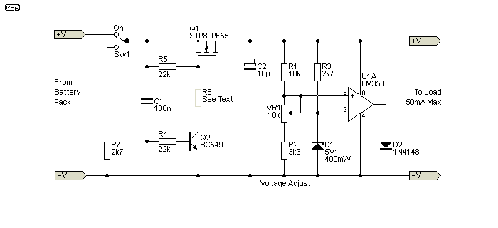
Figure 5 - Adjustable Under-Voltage Cutout (5 - 10A Output)
VR1 has more than enough range to suit three and four cell Li-Ion battery packs. This lets you set the cutout voltage very accurately, and small zener voltage variations are also accommodated. Needless to say, the same arrangement is just as applicable to the Figure 2 circuit, and overall is the most flexible. Since the voltage can be set accurately, this is likely to be seen as a better alternative than a fixed circuit, although testing has shown that the standard arrangement shown in Figures 2 and 3 is perfectly acceptable for a standard 3S 11.1V Li-Ion battery pack. The adjustment pot can be used with any of the circuits shown here, including Figure 4.
If the voltage is greater than 16V (4 calls in series), include R6. The value is based on that of R5, and it's intended to keep the gate-source voltage of the MOSFET to no more than 15V. A protective zener diode can be included between the gate and source of the MOSFET for higher voltages.
The circuit shown in Figure 5 also uses a higher power MOSFET, and will be good for 5-10A output, and R5 has been reduced to ensure a faster turn-off. Depending on the actual current, the MOSFET should not require a heatsink, as the STP80PF55 shown will dissipate less than 200mW, even at 10A output current. With a heatsink, you can use this up to 25A or more. Be aware that with a 25A current draw, almost half a volt will be dropped across the MOSFET, and it will dissipate over 11W. Consider using MOSFETs in parallel, and reduce the value of R5.
With any high current version, the cutout voltage must be set while monitoring the input voltage (directly across the battery), and not the output voltage. This is because there is some voltage 'lost' across the switching device, and the cutout voltage will be too high if you monitor only the output voltage. To reduce the voltage dropped across the MOSFET, two (or more) can be used in parallel.
If you need a very low current version, you can use the LM285LP-2-5, a 2.5V, TO92 fixed voltage reference. With a typical operating current of only 8µA (15µA 'worst case'), this will keep operating current to the bare minimum. This is only important for very low power circuitry, so a small MOSFET can be used and R5 can be a much higher value as shown. The LM358 remains the preferred opamp with a supply current of 500µA, and while there are opamps with lower supply current most are harder to get, more expensive, and/ or are only available in SMD packages. Many also have very limited supply voltage (some are limited to 5V). With the circuit shown, the total current drawn by the cutoff circuit will be no more than 800µA (not including the load, of course). As with the others shown here, the current when it turns off is effectively zero, limited only by MOSFET leakage.
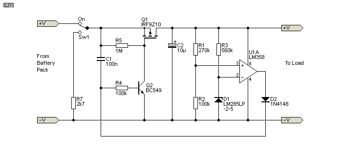
Figure 6 - Low Power Under-Voltage Cutout
With the values shown, the cutout is a little over 9V, but that can be changed by using a trimpot. I leave the finer details to the constructor, but Figure 5 shows the basic scheme, although the resistance will be higher (a 100k trimpot and 33k would be suitable). Alternatively, you can use a 300k resistor for R1 to set the voltage to 10V. While this very low power circuit may be appealing, the high resistances and somewhat more obscure voltage reference mean that it's no longer a 'junk box' project, as few people will have the LM285LP-2-5 in stock. Note the relocation of R6 - it may not be needed, but if you were to use a lower power opamp it ensures that Q2 (and Q1) remain off properly. Not all low power opamps can get the output voltage to less than 20mV, and Q2 must be able to turn off completely to prevent leakage when the circuit is off.
Operation is identical to the other versions shown. If you really do need the current drain to be as low as possible, this is appropriate, but the high resistance values mean that it's more susceptible to noise, and you might need to add a 10nF capacitor in parallel with R2. While this version hasn't been built and tested, a simulation shows that it does work properly, although the simulator underestimates the total current drain. Personally, I'd only consider this for very low current loads, as the others shown are likely to be more resistant to noise - especially if the load includes a switchmode power supply.
Before connecting the selected circuit to your battery, it's essential that it's tested thoroughly. A fault can cause untold damage, both to the circuit and the battery. While the fuse will prevent a catastrophic failure, it's still easy to damage parts and it's likely to be irksome to fix once it's been assembled. You need a variable power supply to test the circuit, along with at least one multimeter and ideally an oscilloscope. You should also connect a suitable resistor as a load (at the output of the cutoff circuit. The value depends on the current you wish to test with, but a 560 ohm resistor will work for any variation (just under 18mA at the cutout voltage for a 3S battery pack).
Set the power supply to about 11-12V DC, and if it has current limiting, set that to less than 100mA. Turn on the power switch to the cutout circuit, and verify that the output voltage comes up to the full supply. Turn off the switch, wait a second or two, and turn it on again. Voltage should instantly come up to the full supply. Now slowly reduce the input voltage. When it reaches about 10V, the circuit should turn off, and no current will be drawn from the power supply.
Verify that turning it off and back on again produces nothing more than a 20ms (or thereabouts) attempt at supplying output voltage, and then turns off again. The output pulse is due to the kick-starter capacitor (C1) turning on Q2, and power turns off again because the comparator detects that the voltage is below the threshold. That means that the output of U1A will not go high to keep the circuit operating. If the value of C1 has been increased the output pulse will be longer.
Set the power supply to 11 or 12V, and try again. Normal operation should result. Check the cutout voltage as many times as you need to be satisfied that it's at the required voltage. If you included a trimpot, set it to maximum resistance, and set the supply voltage to the desired cutout voltage. Adjust the trimpot slowly until the output switches off. Verify that the circuit switches off reliably at the desired voltage, and correct the trimpot setting as required.
The second half of the opamp (U1) can be used to derive a half voltage (artificial earth) so your circuit can be used with dual supply voltages. This is a common circuit, and is used in a few ESP projects and can be found on the Net. There's nothing special about it, and it will perform well with most dual-supply circuits. The input voltage (from the battery and via the cutout circuit) can be up to 30V, which means you can use up to eight Li-Ion cells in series, but it's unlikely that anyone will go that far.
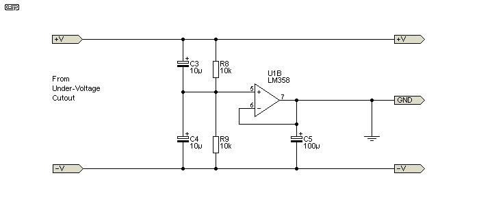
Figure 7 - Artificial Earth Circuit
R8 and R9 derive the half voltage, bypassed by C3 and C4. C5 ensures that the circuit's output retains a low impedance (and low noise), and will be suitable for most common circuits. There are likely to be some projects that have a different current drain from the +ve and -ve supplies, and if that's the case you might need something more elaborate than the simple arrangement shown. Note that neither side of the battery can be connected to the chassis (earth/ ground), as that will cause the circuits to malfunction.
The artificial earth circuit isn't limited to this project, and it can be used with any DC power supply that has a single output. For example, if you have a 15V DC wall transformer supply, this circuit (with any opamp you like) will convert that to ±7.5V which will drive most projects shown on the ESP website. This will only work for projects that draw roughly the same current from each supply, as the 'earth' provided can't handle more than a few milliamps of unbalance.
Given the popularity of Li-Ion cells and batteries, one might imagine that an IC would be available to perform cutoff in a similar manner to that shown here. In fact, ICs are available, but most are in SMD packages only, and many actually need more support parts than the circuits described. While they do provide additional functionality (some include balance circuitry for example), many that I've come across in searches are fairly basic, but expect to be connected directly to a single cell, and their (very small) current drain may cause the battery to be damaged anyway if left long enough. The circuits described here draw (close to) zero current once they switch off, so the risk of battery damage is greatly reduced. There will always be some small leakage current through the MOSFET, and that's available from the datasheet. It's usually less than a few µA.
A few circuits can be seen on the Net if you do a search, but nothing I saw has the flexibility of these designs. Overall, a search will reveal far more questions than answers, with many queries posted on forum sites. Some of the circuits you might see rely on specialised parts that you may find difficult to find, making the project either impossible or expensive. Since standard parts are used throughout, the circuits shown here can be built using Veroboard, and the entire unit can be made small enough to fit almost anywhere. Specialised ICs are often very user-unfriendly, because most are SMD and can't be wired up on Veroboard or similar. They are also (mostly) considerably more complex than the arrangement shown, and none that I saw is capable of turning itself off once the voltage falls to the minimum. That means there will always be some drain, which although small will continue to discharge the battery even after the load has been disconnected.
While many of the available circuits will be fine for model cars, boats, aircraft and other similar devices, all of those available only disconnect the load. This doesn't matter if the system is monitored by the user (as will be the case with all modelling applications), because batteries will usually be disconnected and recharged within a short period after the cutout operates. This is not the case with much other gear though, and the circuits here are specifically intended for total protection of possibly unattended equipment that's been left on, accidentally or otherwise.
Although I've shown most of the circuits with fairly low current switching devices, you can use a much larger MOSFET for high current operation. R5 (normally 10k) will have to be reduced to ensure that the MOSFET turns off quickly. If this isn't done, a high current load may easily destroy the MOSFET because it will turn off slowly with such a high value. Even a 10A load will cause a worst-case instantaneous dissipation of up to 50W (still assuming a 3S battery) as the MOSFET turns off, and it's important that such a high power is produced for the shortest possible time. Note that other circuit changes will be necessary if you do use a larger MOSFET (or several in parallel). In particular, Q2 will need to conduct more current, so R4 may need to be a lower value, and C1 may have to be increased in value (where the output has a large capacitive load).
This design was originally developed for one of my own pieces of test equipment, and I used parts that I had to hand. Anything even remotely obscure was not an option, and you may even have many of the parts needed in your parts collection. One thing that I have not addressed (other than in passing) is the charge regime. I strongly suggest that you read the Lithium Cell Charging & Battery Management article for information on how to charge lithium cells and batteries safely. There is no doubt that a simpler circuit could be used, but it's something that needs to be low power, accurate and reliable and further simplification would diminish one or all of those requirements. After this article was almost complete, I came across one other circuit that disconnected itself, but the current drawn was greater than some of the projects it might be used with. Needless to say, that's not something I'd recommend.
While I've concentrated on Li-Ion batteries, the circuit will work with any battery chemistry. The voltage needs to be changed to suit, but it can be used with SLA (sealed lead-acid) or wet-cell lead-acid batteries just as easily. It's also suitable for LiFeP04 (lithium-iron phosphate) batteries, which are becoming popular because the charge regime is not as restrictive and they are far safer (little or no risk of fire for example). Note that LiFeP04 batteries are 3.2V/ cell, and not the 3.7V/ cell expected for Li-Ion. All batteries will be damaged by excessive discharge, and adapting the circuits shown to different cutout voltages is as simple as adjusting the pot shown in Figure 5.
1 Premature Voltage Cutoff - Battery University
There are no other reference, as this is an original design, based on first principles of electronics.
| Main Index
Projects Index
|