
|
|
| Elliott Sound Products | project 158 |
A test preamp is a useful piece of workshop equipment, allowing you to measure and listen to very low level signals. Even at their most sensitive setting, most oscilloscopes are not sensitive enough, and the input stage is usually very noisy. Most oscilloscopes have a maximum sensitivity of around 2mV/ division, but if you are looking at a 500µV signal you see very little on the trace, other than the oscilloscope's front-end noise.
AC voltage measurements are no less troublesome, even with an AC millivoltmeter such as that described in Project 16. A calibrated test preamp allows you to not only look at the low level signal waveform, but you can hook the output up to an amplifier and listen to it as well. The one I built doesn't get used very often, but when it's needed there really is no alternative. You can also measure the output noise of power amps, preamps and regulated power supplies, something that's usually somewhere between difficult and impossible.
The frequency range needs to cover the audio band, with at least some 'reserve' bandwidth either side, which means flat response from 10Hz to at least 30kHz. The gain ranges I used cover 3 decades, from x10 (20dB), x100 (40dB) to x1,000 (60dB). Since this preamp is unlikely to be in daily use, it's important to keep the total cost to a minimum. Exceptionally quiet opamps and hybrid designs are available, but usually at significant cost for a premium opamp or a lot of messing around for a hybrid design. An ideal opamp would be the AD797 (typically 0.9nV√Hz), but at around AU$15 each for a single opamp, that's not going to be viable for most home constructors.
Hybrid designs using low noise bipolar transistors or JFETs (usually with several devices in parallel) can also give very good results, but at the expense of limited input voltage range, difficulty sourcing the parts, and comparatively complex circuitry.
It is important that the preamp should be easy to construct, and it should also make it easy (or at least possible) to hear the noise from a 1k resistor (approximately 4.1nV√Hz at 25°C room temperature, or 578nV for a 20kHz bandwidth). This sets a baseline that lets users understand the most fundamental aspects of noise in electronic circuits. For those who haven't done so, read Noise in Audio Amplifiers, as this gives a good overview of the different types of noise and how it is generated and referred to in datasheets and other literature.
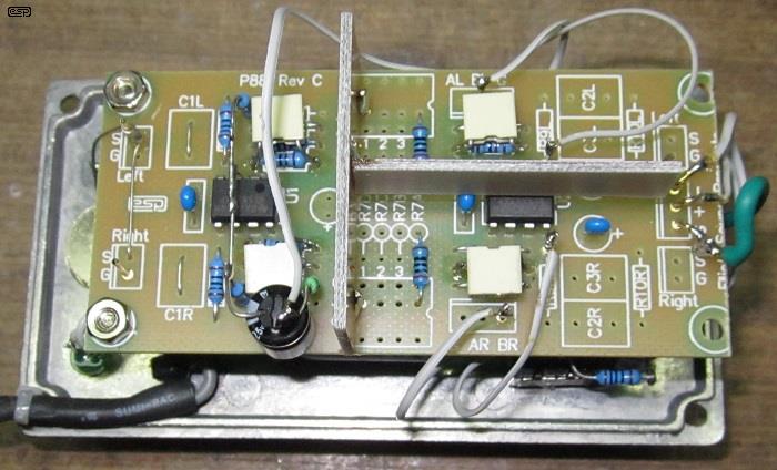
The photo above shows the insides, and I built mine using the Project 88 preamp PCB. Note the shields between the sections. Without these, the circuit may oscillate when set for maximum gain (1,000 or 60dB), and if you don't limit the bandwidth and use shields, yours may too. The 1nF capacitors limit the high frequency -3dB frequency to 88kHz, and with 3 cascaded stages the upper -3dB frequency is 41kHz. Without these caps, you will almost certainly get high frequency oscillation at maximum gain. The capacitance can be reduced to increase the bandwidth. If you use 220pF caps instead of 1nF, the bandwidth at a gain of 1,000 is 160kHz. Having modified mine from 220pF to 1nF I strongly advise that you use 1nF as shown in the schematics.
The preamp is fairly quiet, which is testament to the low noise from NE5532 opamps. They are rated for a noise level of 5nV√Hz at 1kHz, which means that the equivalent input noise will be about 707nV (each), so with a total gain of 1,000 and the parallel input stage we can expect an output noise of about 500µV from the opamps with the input shorted ... at least in theory (and when noise is measured using a bandwidth of 20kHz).
Half a millivolt of output noise might seem fairly high, but remember that if you have an input signal of only 100µV, the signal output will be 100mV, so the signal to noise ratio will be greater than 40dB. This isn't wonderful by any means, but it's far better than you can get from an oscilloscope, and it lets you listen to very low level signals. Note that the above figures assume a zero ohm input, so with real-life signal sources the noise level may be higher. And yes, you can hear the noise from a 1k resistor using this preamp.
In reality, there is also a noise contribution from the feedback resistors, so the total output noise will be somewhat higher than the above indicates. The following two gain stages don't add as much noise as you might imagine, because the signal has already been amplified. The noise from the first amplifier will always be dominant. The first amplifying stage is the most critical for noise performance. I measured a total (wide band) output noise of 1.2mV with a 100 ohm source. This fell to 480µV when band limited to 20kHz. The full range noise rises to around 4mV with the input open - the increase is mainly due to the noise generated by the 10k input resistor (about 1.83µV at 25°C).
To give you an idea of just how sensitive the preamp is, I listened to the radio in my workshop, with the signal attenuated by 10,000 using 1Meg and 100 ohm resistors. The input level was set to 150mV (RMS), so the attenuated level was only 15µV. After amplification (x1,000), there was a small amount of audible hiss, but the signal was perfectly ok to listen to, having been boosted back to 15mV by the preamp. It was also possible to get a reasonable oscilloscope trace, although it showed quite a bit of high frequency noise until I used the oscilloscope's inbuilt filter to remove everything above 20kHz. Needless to say, the attenuated signal was completely inaudible through my workshop amp system, and could not be seen at all on the oscilloscope. The ability to measure or listen to a signal as low as 2µV RMS (with around 12dB signal to noise ratio) isn't a daily need, but when you do need it you'll be glad you took the time to build this project. 
It's also worth mentioning that you can use the NE5534A (single opamp) for the first stage. These have a typical equivalent input noise of 3.5nV√Hz at 1kHz, and one of these will (probably) be as quiet as the paralleled NE5532s. The downside is that you can't use any of the ESP circuit boards because I use dual opamps almost exclusively. You can improve S/N ratio by using NJM2068 opamps. These are readily available, little known, and are about 3dB quieter than an NE5532 (C3 will need to be reversed in polarity because the NJM2068 uses PNP input transistors). You can also use the LM4562 which has slightly less noise but is an expensive opamp compared to the others suggested. AD797 opamps can also be used (but at considerable cost), and being a single opamp it won't work in the P86 PCB. These have an input noise of 0.9nV/√Hz.
With the values shown below, you'll get a theoretical signal to noise ratio (S/N) of around 51dB for an input signal level of 200µV using an NE5532, or 54dB is you use the NJM2068 (with both halves of the dual opamp in parallel). Although this could be improved by about 1dB by using feedback resistors of 180 and 20 ohms, the opamps will be unable to drive the load with more than a few millivolts signal level. For 1dB improvement, this is an unacceptable compromise, and the values I chose are preferred.
The circuit is straightforward, but designing for low noise and extremely high gain is challenging. The first stage is the most important, as that sets the noise level when higher gain settings are used. I used cheap but excellent NE5532 opamps throughout, and the overall performance is very good. It's not the quietest preamp possible, but it's not expensive to build and it does what I need. You could also use LM4562 opamps (2.7nV√Hz) and while they are more expensive you can expect good results. The LM4562 also has a lower input bias current, so DC offset will be reduced. Feedback resistors are all low values to minimise noise. They are a compromise between noise and opamp loading, and the values shown give good results based on my prototype unit.
To minimise noise further, the first stage is operated with two opamps in parallel. You can use more, but it's doubtful if the end result is worth the extra hassle, and the DC offset will be increased. When two opamps are used as shown below, the signal is identical in each opamp, but the noise is uncorrelated. When two noise sources are summed, the output level only rises by around 3dB, or in the case of the arrangement shown, the overall noise level is effectively reduced by 3dB. Another two opamps in parallel (four in all) will reduce the noise by ~6dB.
You need to understand how this works. Imagine two random noise sources, each with an output of 1V RMS and summed together. If they were perfectly in phase, the output level would still be 1V RMS, but they're not in phase because the noise is random. When added together, the total is ~707mV RMS, 3dB lower than you may have imagined. We use this to our advantage for the first stage. If four noise sources were operated in parallel, the noise would be reduced by 6dB (500mV). Exactly the same principle applies with the opamps. I have shown two in parallel because that's what I used in my preamp. Although you can use four, for the purposes this unit will be used for I doubt that it is necessary.
The band limited (20kHz) output noise with a single opamp in the first stage measured 640µV, falling to 480µV with two in parallel, a 2.5dB improvement (measured with the full 60dB (×1,000) gain selected). Not quite the 3dB hoped for, but a worthwhile reduction. Needless to say, using quieter opamps will improve this, but as a general purpose preamp it does everything I need and will most likely do the same for you. This gives a signal to noise ratio of just over 46dB with an input of 100µV.
As you can see, the two opamps have separate feedback networks, but they share the input resistor (R1) and protection diodes (D1 & D2). All the other parts that make up the first stage are in parallel, so resistor values are all effectively half the actual value. This helps to minimise resistor thermal noise. One thing that the NE5532 is not renowned for is DC offset, and the circuit shown won't disappoint - it will have at least -31mV of DC offset with no input source connected (each half of the opamp contributes about 15mV offset). This is reduced to around -5.5mV when a low impedance signal source (< 100 ohms) is used. While the DC offset can be reduced by using caps in series with R5 and R7, they have not been included because a large value (at least 470µF) is needed in order to get good low frequency response.
The input impedance is 10k (close enough), simply because having a very low input impedance limits the usefulness of the preamp, and a high input impedance isn't very useful either. Most low-level signal sources have a low impedance, and 10k is a sensible compromise. You can change it if you want to by using a different value for R1, but note that higher values will cause more DC offset.
The preamp's voltage gain (Av) is determined by the feedback resistors. The gain of an opamp is given by ...
Av = ( R4 / R5 ) + 1 (using only the parts around U1A), so ...
Av = ( 1,800 / 200 ) + 1 = 10 (20dB)
Naturally, the accuracy of the gain is determined by the accuracy of the resistors. For general use 1% metal film resistors will be quite alright, but feel free to select them for closer tolerance if you prefer. Close matching will also help minimise any circulating current through R8 and R9, but with 22 ohms as shown there will usually only be a few microamps at most.
Because of the DC offset, without C3 there would be up to 3.1V of DC at the output of the complete preamp at maximum gain, because the next two stages would amplify the 31mV by 100. C3 keeps the offset to manageable levels, but being a large value it has little effect on the low frequency response (-3dB at 0.32Hz).
D1 and D2 will help prevent opamp damage, but if you do something silly you can still blow up the input stage. Because the diodes connect to the supplies, a low impedance voltage source may boost the preamp's supply voltage far enough to cause damage. An input series resistor cannot be used because it will affect the noise performance, so always take great care if you are monitoring anything that has a DC voltage present. You'll also need to include a 1µF coupling capacitor to the input when measuring voltage regulator noise (for example). A coupling cap is not included because it restricts the low frequency response and increases low frequency noise.
The next two stages are conventional, and use each half of the second NE5532. Each has a gain of 10, and with the two cascaded the total gain is 100. Each stage must be disconnected from the preceding and following stages if it's not being used. If this isn't done, the following opamp will clip heavily, and distortion will be apparent at the output. Fortunately, this is easy using a pair of DPDT toggle switches. The next two stages have a resistor from the non-inverting input to ground, because without them the opamp outputs would swing to the full DC supply (and possibly oscillate as well) when switched out.

The second and third gain stages use each half of U2, another NE5532. Each has a gain of 10, so when cascaded the total gain is 100. The switching is arranged so that stage 1 is always in circuit, as unity gain isn't provided or necessary. Either stage 2 or stage 3 can be switched to give a gain of 100, and with both in circuit the gain is 1,000 (60dB). The preamp's output includes a final output capacitor to minimise the DC offset, and there's a 100 ohm series resistor to prevent instability when connected to a coaxial cable.
The switching isn't complex, but cable routing is very important. Each switch either completely bypasses or switches a gain stage into the circuit. The final output capacitor blocks the DC that will appear at the output of Stage 2 or Stage 3. Because the NE5532 opamp uses NPN input transistors, the offset will always be negative. The input resistors for stages 2 & 3 are 10k, and are needed so the opamps have a zero volt reference when switched out of circuit.
Note the shields between each stage. These are easily made using a small piece of tinplate, or you can use small pieces of copper-clad PCB material as seen in Figure 1. Aluminium is not suitable because you can't solder to it. The shields isolate each section from the next to prevent oscillation or instability at high frequencies.
Gain dB -3dB Bandwidth At 20kHz x 10 20 dB 82.4 kHz -0.25 dB x 100 40 dB 52.9 kHz -0.5 dB x 1,000 60 dB 41.8 kHz -0.75 dB
The above table shows the gain and response for each range. Reduce the 1nF feedback caps for improved high frequency response, but be aware that noise will also increase. The minimum capacitor value recommended is 220pF, which (theoretically) gives a -3dB bandwidth of 158kHz with 20dB of gain. In reality it will be less than this. Distortion was checked with a distortion meter, but it's immeasurable, being below the noise floor. See Figure 7 for the spectrum captured with full gain (60dB).
The external power supply you use has to be regulated and noise free, and also must be floating (i.e. neither lead connected to mains earth or the diecast enclosure for the preamp). I included extensive filtering on my unit, but even that's not good enough if you use a switchmode power supply. The high frequency noise will manage to get through, and although it's not audible, it makes an oscilloscope trace very messy and prevents you from being able to see low level signals cleanly.
As shown below, the DC input is filtered by a pair of 10 ohm resistors and two 1,000µF capacitors. 100nF caps are also included to ensure a low impedance at very high frequencies. The filtering won't eliminate hum, but most noise is suppressed fairly well provided the supply is reasonably noise-free to start with. C11 and C12 are connected as close as possible to each opamp package. If you use the recommended P88 PCB, there is provision on the board for these caps, as well as C9 and C10.
The DC input can range from around 10V up to a maximum of 30V. For most purposes, a voltage between 12V and 24V will be the easiest to provide and will give good performance. NE5532 opamps will run quite happily from as little as ±3V, but that limits the available headroom and means that the maximum output will be less than 2V RMS at the onset of clipping. I have a range of bench supplies available, and generally use the preamp with about 15-20V DC input.
The LED is optional but recommended so you know that the preamp has power available and it's the correct polarity. D3 prevents an accidentally reversed supply from damaging the opamps. NE5532 opamps draw more current than many others, so allow at least 30mA from the power supply to power the preamp.
Construction overall is fairly critical, due to the very high gain and reasonably wide bandwidth of the preamplifier. Because each constructor will use a different arrangement based on the enclosure they use, it's not really possible to show a recommended layout. It's very easy to transpose the circuits shown to a P88 circuit board, and the only thing remaining is the switching, input and output connectors and the power supply. All of these can be mounted on the front panel of the box.
The preamp must be installed in a metal enclosure to prevent hum pickup, and a diecast aluminium box is recommended. Wiring from each preamp to the switches doesn't need to be shielded, but all inputs and outputs must be well separated so the circuit doesn't oscillate at any gain setting. As I found when I built my unit, without the 1nF caps across each 1.8k feedback resistor the preamp will oscillate at maximum gain. As noted earlier, you can use 220pF or 470pF NP0/ C0G ceramics for wider bandwidth if you prefer.
All resistors must be metal film. The use of any other type will increase the noise generated in the preamp, making it far less useful. Multilayer ceramic capacitors must be placed as close as possible to each opamp package. All coupling and filter caps will be electrolytic types, and if possible use low leakage types for coupling (C3 and C6). If you want to use an opamp other than the suggested NE5532, you will need to determine the polarity of any DC offset. Provided it is below 100mV, standard electrolytic caps will not be damaged even if the polarity is reversed, but it doesn't take much effort to verify the offset polarity before coupling caps are installed. The 1nF caps should be MKT 'box' polyester or similar.
For inputs and outputs, I suggest BNC connectors. This allows you to use a x1 oscilloscope probe at the input, and a BNC to BNC lead from the output to your oscilloscope. You can include RCA connectors or 3.5mm mini-jacks for input and output as well if you wish.
The power supply can be assembled on a separate piece of Veroboard, or can be hard-wired and attached to the inside of the front panel with double-sided adhesive tape or silicone. There's not a great deal to it, and construction of the power supply is not at all critical.
The input and output BNC connectors (and RCA connectors if you wish) should be the only direct connection to the case. If you use a plastic case, the metal lining can be aluminium foil, carefully stuck onto the inside of the case with spray adhesive. Make sure that you provide a good electrical connection between the sections if the case has any detachable panels, and make sure that any foil cannot become detached and make contact with any internal circuitry.
Because of the large value filter and coupling capacitors, the preamp will take a few seconds to settle before it's ready for use. This circuit makes no pretence of being the ultimate in low-noise amplification, but it's a very useful workshop tool. There are exotic opamps that will out-perform the circuit shown, but for 99% of applications the system as described will be more than acceptable. With response extending from below 10Hz to at least 30kHz, there aren't many audio signal sources it can't handle. This preamp is intended to amplify signals in the audio range only - there's not a lot of use having a preamp like this which amplifies signals you can't hear. All that does is increase the noise, making low level measurements much more difficult.
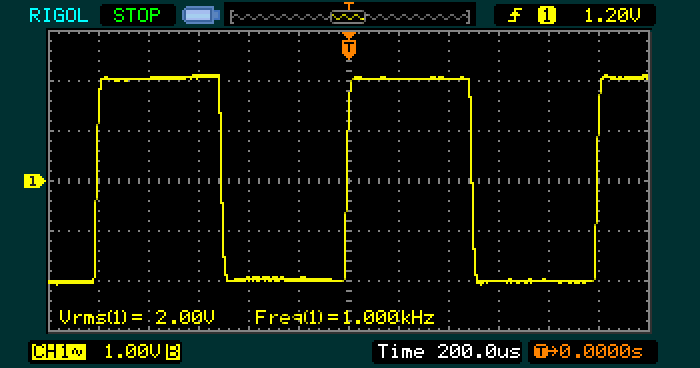
The above shows the output with the gain set to 1,000 - the input is a 1kHz, 2mV RMS squarewave. Response extends to beyond 30kHz, and that can be improved by reducing the value of the 1nF feedback caps. Doing so may compromise stability, and will increase the output noise (wider bandwidth = more noise). With such a high gain, it's possible to examine, measure and listen to very low level signals. For example, if the input is connected to an old tape head or a small inductor, you have an excellent tool for monitoring the stray magnetic field from transformers. You can also use it to test the voltage generated in a chassis by a transformer, simply by connecting the input between two points on the chassis.
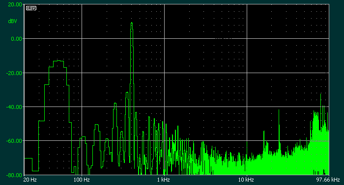
The spectrum shows the preamp with pretty close to worst-case settings - the gain is 1,000 (60dB) and the input signal is only 2.48mV, and the input wiring was (deliberately) somewhat untidy. The input was fed from an attenuator of about 2,000:1 wired using clip leads (so it picked up hum). There is no evidence of distortion products, and at the low input level used they could be ignored anyway. This is a test preamp, and it's not designed to be hi-fi, but it still performs surprisingly well.
One use that will interest those who play with guitar effects is something I have used mine for on a number of occasions - checking the output of spring reverb tanks. In case you were wondering, a gain of 100 is pretty much perfect, and shows clearly that NE5532 opamps are very well suited for use with the medium impedance output transducers (probably the most common). The benefit of the switched gain arrangement used is that you can select the gain actually needed for a measurement - you are not limited to a single gain of (say) 60dB. Most measurements and tests will need a gain of 40dB (100), and many will be easily satisfied with a gain of 20dB (10).
At maximum gain you will be able to measure the voltage developed across any two parts of a metal chassis, and there is no better way to understand earth loops. It can be quite surprising to listen to just how much mains hum signal can be developed across a short loop of cable (or a sheet of aluminium) when there is a transformer nearby. With the ability to make signals of only a few microvolts audible, your test and measurement options are greatly expanded.
You can also use this preamp to listen to noise from regulated power supplies, but be aware that you must use a capacitor to couple the input, and you must also provide some protection against high level transients when the input is connected or disconnected. Failure to protect the input stage will result in damage to the opamp. Although the schematic in Figure 2 shows diodes, you will need to include some (external) series resistance as well. You can use a 1µF cap for coupling, which gives a -3dB frequency of 16Hz into the 10k input impedance.
For anyone who wishes to experiment with low noise amplifier designs, a high gain preamp is the only way you'll be able to obtain a meaningful indication of the circuit noise. For example, you will definitely need something like this project to be able to measure the noise from moving-coil phono pickup 'head' amplifiers, microphone preamps and other low-noise circuitry. You can also verify that resistors make noise, and that some types are much worse than others. For example, compare a carbon composition and metal film resistor - the excess noise from carbon composition types will usually be immediately apparent.
This is one of those projects that you probably won't use too often, but once you have one it opens up a whole world of new measurements that you may never have thought of. Mine has been in use for some time now, and I don't recall what I was doing when I decided that I really did need to have a preamp with a high gain and reasonable calibration so incredibly small signal levels can be measured easily. Now I wouldn't be without it.
Op-Amp Noise Calculator
Small Signal Audio Design - Douglas Self (ISBN 978-0-240-52177-0)
 Main Index
Projects Index Main Index
Projects Index |