
|
|
| Elliott Sound Products | Project 16 |
 Main Index
Projects Index Main Index
Projects Index
|
Please note that the circuit described here has been superseded by Project 236, which covers the range from 300µV to 30V in 10dB steps. The new design has flat response to 250kHz, and while it is more complex it's a better design overall. The article includes detailed explanations of each section (especially the attenuators, which are the heart of any test instrument).
When performing any tests on an audio system, some form of measuring device is essential. Digital multimeters are not useful, since they will not give the true picture of what is happening, and most have a fairly limited frequency range. An oscilloscope is the ideal tool, but not all hobbyists can afford the outlay for a scope, and would find justifying the not inconsiderable cost a tad difficult.
An AC millivoltmeter - calibrated in dB - with a range of 30V down to 3mV full scale (80dB range) would be extremely useful. Attach a microphone (electret mic capsules are quite good), and you have a relative sound level meter, even better if you have some way of calibration.
The meter presented here has a very wide frequency range, and uses a switched attenuator for range adjustment. The attenuator uses the 30-10-3 sequence, which provides 10dB steps between ranges. The standard attenuator provides an input impedance of over 2M Ohms, but is a nuisance because with such high impedances stray capacitance causes havoc with the calibration, so a parallel capacitive attenuator is also needed. If you expect to work with valve amplifiers, you will want the high impedance, but otherwise the low impedance attenuator should do nicely.

| Note Carefully: The meter described does not have protection for the JFET, so if you connect to a high voltage on the 3mV range the JFET will be destroyed. This was a conscious decision, because adding protection diodes would increase the input capacitance of the circuit. This would limit the high frequency performance dramatically. In general, with any meter of this type, the attenuator should always be set for a high voltage (e.g. 30V) before connection, especially if measuring signal voltages with a high DC voltage present (such as valve [vacuum tube] circuits). |

Typical Completed Instrument
When built, the above is what the instrument could look like. A great deal depends on the meter movement you use, as its physical size dictates the height, and the case must be wide enough to allow space for the rotary switch and the on/ off/ battery test switch. This may be a 4P-DT (four-pole, double throw, centre-off) toggle, or a 4-pole rotary switch. The latter will take up a lot more room, so the case will need to be wider. A LED indicator is entirely optional, and it's not shown in the schematics. If used, I recommend a 'ultra-bright' type, which will give a good indication with as little as 500µA (use a 15k resistor to limit the LED current). If used, the LED and its resistor should be across the -9V supply to balance out the JFET, which is powered from the +9V supply only.
The design of attenuators is a topic unto itself, and is described in detail in the article The Design Of Meter (And Oscilloscope) Attenuators. The process is fairly straightforward, but it requires a lot of calculations. My recommendation is to build a spreadsheet (using OpenOffice for example), which is a bit of a chore but the article shows a suggested layout that's not hard to reproduce. Unfortunately, spreadsheets don't provide the option of engineering units (Meg, k, units, m, µ etc.), and scientific notation is a pain to work with. If you were so inclined you could write a computer program to calculate the values for you, but that would be a fairly serious undertaking if it were to be 'universal'. Weird resistor (and capacitor) values are normal, which can make wiring a pain. Part of the 'trick' is to try to arrange the values to suit those found in the E12 or E24 resistor series.
Two attenuator networks are shown in Figures 1 and 2, with a 2-stage version shown in Figure 2A. As you can see the Hi-Z version requires all those capacitors and they must be accurate, too. Otherwise high frequency performance will be all over the place, so you need a capacitance meter or a source of close tolerance caps. The resistors are standard E12 series 1% metal film types, and the caps (if used) should ideally be polystyrene or polyester, but ceramic caps will be used for values below 1nF. Make sure that the ceramics have low thermal drift - NP0 or C0G. The attenuator's input impedance is 2.18MΩ (1.97MΩ with R0a and R0b), in parallel with about 10pF (allowing for connector and wiring capacitance).
Figure 1 - High Impedance Attenuator (Zin = 1.97MΩ)
Note that C10 (32nF) really is 32nF, and will have to be built up from smaller caps (i.e. 27nF || 4.7nF || 330pF) or selected from a batch. The capacitor tolerance ideally should be the same as that for the resistors - 1% is suggested to get acceptable accuracy. You almost certainly won't be able to buy the caps with 1% tolerance, and you'll have to resort to using a capacitance meter to select values. They are just as critical as the resistors, but only at high frequencies (above 10kHz).
With the Lo-Z attenuator, performance can be expected to be quite linear up to around 80kHz before stray capacitance starts to influence the measurement. Without the paralleled capacitive attenuator, the Hi-Z version will start to show incorrect readings at 10kHz or less, which is unacceptable. The stray capacitance comes from the switch contacts and the proximity of the resistors to each other, and only a few pF will cause havoc at high frequencies.
To minimise capacitance, mount all resistors (and capacitors) directly off the rotary switch, and keep them as far separated from each other, the chassis and the remainder of the circuitry as possible. Do not be tempted to try to make the arrangement nice and neat (with all the components nicely aligned with each other), as this will increase the capacitance of the circuit and ruin the high frequency performance. All component leads must be as short as possible. With an impedance of 2MΩ, just a 10pF of stray capacitance will cause a 3dB loss at only 8kHz, so minimising capacitance is critical.
The capacitive divider minimises the influence of stray capacitance, but it doesn't eliminate it. You may find that it's useful to use a trimmer capacitor in place of C2 (4.7pF). The value should be in the range from 2-10pF. An alternative is known in RF circles as a 'gimmick' capacitor, made by twisting two insulated wires together (or one insulated, with a bare copper wire wrapped around it). It's fiddly, but very fine adjustment is possible. Expect up to 1pF/ cm, depending on the insulation thickness and dielectric constant.
Figure 2 - Low Impedance Attenuator (Zin = 214kΩ)
The low-Z version is less susceptible to stray capacitance, but even at 150k (the highest value resistor in the circuit), only a few pF is needed to start to have an adverse influence at 100kHz or so. Again, do not strive for neatness, as this will only degrade performance.
As can be seen, both attenuators have the same ranges - from 3mV to 30V in 10dB steps. Because 10dB is a ratio of 3.16, the scale must be calibrated with two voltage scales, 0-1 and 0-3.16 (sometimes the meter face will show calibrations to 3.2). If you are very fortunate, it may be possible to find a meter with these ranges already (I have used about 3 of them in various projects), but they are now rather scarce. We can blame digital technology for this, but some analogue multimeters might have the scales you need - such a meter will not be cheap, however.

Figure 2A - Two-Stage Attenuator (Zin = 909kΩ)
The two stage attenuator was submitted by a reader ¹. I made some changes to his original submission, but it's still very close. This type of attenuator is very common with oscilloscopes and many older VTVM circuits, as it has the advantage of using fewer precision parts - particularly capacitors. Unfortunately, it requires a dual-wafer 9-position rotary switch. These used to be quite common, but are much less so now. The capacitance values I showed are the 'ideal' case, but they will be unattainable in reality. See the table below for resistor and capacitor values, which give a maximum error of less than 0.1dB, assuming exact capacitance. Using a trimmer cap for the C1 position gives you the ability to adjust the capacitance for minimum error. A value of about 16.5pF is very close to optimum, but stray capacitance will influence the final value.
R8 is shown as optional. It will prevent the meter from flicking when you change range, but it also introduces an error. It's not a big error, but it reduces the input impedance on the 3mV range, and shifts the output from the input attenuator slightly. Note that the JFET stage must be able to handle up to 30mV input without distorting, so its gain must be kept fairly low. After adjusting VR1, the JFET will typically have a gain of about two.
¹ The attenuator circuit was provided by Sten from Denmark. Some values are slightly different from his originals, mainly the capacitors.
Resistors Capacitors R1 969k = 910k + 56k + 3k0 C1 10-20pF trimmer cap R2 30k6 = 27k + 3k6 C2 560pF R3 1k C3 17.2nF = 15n || 2n2 R4 21k6 = 16k + 5k6 R5 6k84 = 6k8 + 39 R6 3k16
The symbol '||' means in parallel with, and '+' means in series. One of the resistor values is only available in the E48 series (3.16k) and it cannot be obtained accurately with any sensible series or parallel combination. 1.0k + 2.2k gives 3.2k, an error of +1.27%. Multimeter selection is possible to get a more accurate result.
The capacitor values supplied by Sten were 22pF (C1), 718pF (C2) and 22nF (C3). These values have a maximum error of 0.25dB. It's up to the constructor to decide what level of accuracy is required.
The amplifier(s) used in such a project are critical - we need wide bandwidth and low noise, coupled with low current drain, since we want to be able to run the meter on a 9V battery. The meter amplifier also requires high input impedance - especially for the high impedance attenuator version. There are a few opamps that will give good performance up to at least 50kHz, but the meter amp is a 'special case', as it needs high gain, a high slew rate and has to feed a very nonlinear load (the diodes). You could try something like the LM318, but despite its speed, you'll be lucky to get much past 30kHz before it rolls off.
Consequently, a discrete opamp is the device of choice, since it can be built to satisfy all the desirable features we need. The input sensitivity of the meter amp is 3mV for full scale deflection on the meter, so it requires a lot of gain. In the final circuit, a JFET is used to provide the necessary high impedance input, and has the added benefit of supplying extra gain - this helps to reduce the demands on the opamp, since a typical 2N5485 JFET in the circuit shown (Figure 4) provides a gain of about 15, raising the input voltage to the opamp circuit to about 45mV for 3mV input.
Figure 3 - Basic Meter Amplifier Scheme
Another requirement is simplicity and good linearity. The basic meter amplifier shown in Figure 3 satisfies all our requirements, but as you can see uses germanium diodes. Although these are harder to get and more expensive than silicon (and have higher leakage current), they also have very wide bandwidth and significantly less voltage drop than silicon, which reduces the requirement of the opamp to have an infinite slew rate.
This basic design has been around for many years, and is still one of the easiest to make, having the minimum of parts. The voltage across R2 must be the same as the input voltage (basic law of opamps) for the amp to be stable, so all losses in the meter and diodes are 'restored' by the opamp. The capacitor will need to be selected for the meter movement you use, since different meters have different damping. Initially this can be left out, but if excessive meter swings cause problems (or pointer oscillation at low frequencies), then the capacitor will be needed. A value of 10µF is always a good starting point.
The input sensitivity is simply set by changing the value of R2 (in Figure 3), with lower values providing higher sensitivity and vice versa. Typically, R2 will be a multi-turn trimpot to allow for calibration. R2 is replaced by a trimpot in Figure 4.
The entire circuit can be built easily on a piece of perforated board (Veroboard or similar is good for this type of circuit), and a printed circuit board is quite unnecessary. Lay the physical circuit out following the schematic layout as closely as possible. This nearly always works well with discrete circuits, and makes it easy to follow 10 years later when you need to fix it. (I have had mine for well over 20 years, and have not had to fix it yet.)
Figure 4 - The Complete Meter Amplifier
Figure 4 shows the complete meter amplifier, and uses a 2N5459 (or similar) JFET for the input. If possible, I'd use a 2N5484 as these are designed for RF and have better high frequency response, but they may be harder to find. The JFET provides a very high input impedance as well as some useful gain (about 15), allowing the entire unit to use a single discrete opamp. Be aware that you may have to search for the JFET - there used to be hundreds of types available, but most have vanished and are no longer available. You need a JFET that's rated for fairly low current (1 - 5mA with zero gate voltage) and a gate-source cutoff voltage of around 2.5 volts. If you try to use a JFET with markedly different characteristics you will need to modify the circuit.
I originally specified a 2N5459 JFET, but they may be difficult to obtain. One suggested device is a J113, but they have high gate capacitance and can't manage high frequencies very well. If available, you can use a BF244, which a reader tells me works very well. Another candidate that seems to be readily available and will work is the BF245A - note that it must be the 'A' version. Because it will be necessary to change the resistance of R2 to get about 5V DC at the drain of Q1, I have changed the circuit to make R2 a trimpot. Vary the trimpot setting to get the drain voltage around 5V. There must be a minimum of at least 3V DC between the drain and source, or the FET will be unable to amplify properly. JFETs have a wide parameter spread, so don't be too surprised if you need to change R3 to get it to work properly. With the trimpot this should not be necessary.
The 'opamp' is a simple 3-transistor discrete design and is used to obtain optimum performance for frequency response, not readily obtainable with standard opamps for this application. The distortion characteristics are relatively unimportant, but the requirement for wide bandwidth and high gain over the entire frequency range excludes most conventional opamps. Use OA91, OA95, 1N60, 1N34A or similar germanium diodes for D1-D4 for best results. You can also try BAT43 Schottky diodes. D5 must be a standard silicon diode.
Note that the FET has no gate resistor, but relies on the voltage divider (attenuator) for its earth reference. This is not generally considered good practice, but it causes only minor 'flicks' of the needle when changing ranges. Also be aware that there is minimal input protection, so if you have the meter set to the 3mV range and connect it to the speaker output of an amplifier, you will probably cause damage. A resistor (10k) in series with the gate is used, but will not offer full protection. A resistor which would offer full protection at any voltage will also cause problems at high frequencies because of its high value. Likewise, the capacitance of protection diodes will also adversely affect the high frequency performance (which is why there aren't any).
The discrete opamp is only a simple design, but manages a frequency response to well over 100kHz (-1dB) with the 50µA meter load, and will operate satisfactorily with battery voltages down to 8V (the lower limit for a 9V battery before its internal impedance rises significantly). 100µF capacitors are used to ensure that the battery supply is bypassed, to help counteract the impedance rise as the battery ages.
I used BC549 (NPN) and BC559 (PNP) transistors, but any high gain, low current device will (should) work fine. As always, all resistors should be metal film, and the two pots should be multi-turn to allow accurate setting. The circuit operates as a voltage to current converter, and the complete amplifier requires 3mV input for an output current of 50µA.
During assembly, it is extremely important to keep stray capacitance to the minimum. The amplifier has very high gain and wide bandwidth, and oscillation will (not might) occur if you are not careful. In particular, keep the leads of C2 short, and make certain that the output (meter) leads are kept well separated from inputs and the attenuator.
If you use Veroboard, make sure that the track strips are cut at each end of each track that joins two or more points of the circuit. This helps ensure that they cannot act as antennas at high frequencies - this may cause oscillation or poor high frequency response, and neither will add to the instrument's usefulness.
The initial test involves connecting the meter amp to the attenuator, and applying power. All wiring must be carefully checked before you do this. The 9V batteries can supply enough current to damage the transistors, but batteries are more expensive than the transistors. A wiring mistake may place a heavy discharge on the batteries rendering them dead before their time. Normally, batteries should last for quite a while, since the current drain is only about 4.5mA.
The meter is provided with protection by D5, a 1N914 (or 1N4148) which will conduct if too much voltage (or current) is applied - the meter will be hard against the stops though, and may still be damaged if the condition is allowed to persist. When power is applied, the meter should flick to full scale, then quickly settle back to near 0 volts. If it remains at full scale, you have made a mistake, so remove power immediately, locate and fix the error.
Calibration involves first setting the Set 0V Offset pot to its midway position, then carefully adjusting until the meter reading is as close as possible to the zero voltage mark. Any remaining offset must be removed using the meter's mechanical zero adjustment - this is a little crude, but there is not much choice with this type of circuit. You will find that the meter reading will drop to some minimum value then start to climb again - this is because of the full-wave rectifier in the meter and feedback circuit.
Next, an accurate voltage at somewhere between 100 to 2,000 Hz is used to calibrate the meter. Select a suitable range on the attenuator, then adjust the sensitivity control until the meter shows a reading that is identical to the applied voltage. Where possible, this should be done with the millivoltmeter at full scale on the 1V range. Remember that the scales are different for 1V and 3V ranges. The sensitivity pot will have more than enough range to allow the unit to be calibrated, provided no wiring mistakes have been made.
If by some chance your version decides it wants to oscillate at a MHz or three, you will need to add a small capacitance between collector and base of Q4 - I would not expect that more than 10pF should be needed, and even this will reduce the high frequency response slightly. Mine has a -1dB upper frequency limit of about 250kHz, a frequency which is more than adequate for audio use (by nearly an order of magnitude), but this is without a frequency limiting (miller or dominant pole) capacitor.
It is important to obtain the best meter movement you can find, or the unit will be hard to read and possibly inaccurate. You will need to make a new scale for the meter, showing the two ranges and a dB scale. One possible reproduction is shown below, and there are links to a couple of others, one of which should suit whatever passes for a fairly standard 50µA movement - these should be available wherever you are, but you might need to look around a bit.
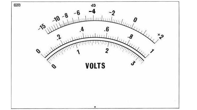
Figure 5 - Meter Face
The alternate meter faces are Meter Face 1 and Meter Face 3 - One of these should be able to be resized to suit the movement you use, but some experimentation is needed. You will notice that #3 appears to be hand-drawn in some areas - that's because it was. This is a scan from my own millivoltmeter, and when it was built, all these new-fangled scanners and computer thingies were a bit less common than today (you can gather from this that I have been using the meter for quite a long while).
To see what you are trying to find, check out this link to an Australian company called Jaycar Electronics. This is a link to the company website, and you will have to search for the movement (I used to have a link to the picture of the meter itself, but Jaycar has changed their website and the link was broken). Those available are not great meter movements, but are similar to the one I am using, and work quite well.
A typical 50µA movement will have a resistance of around 2k to 3k Ohms, and on average, expect to pay about AU$20 (or about US$15 or so) for a passably good movement.
When completed, the meter can be calibrated against a known accurate digital multimeter, using a frequency of about 100Hz (most digital meters will give an accurate reading at this frequency).
If you would like to be able to measure the battery voltage without dismantling the instrument (this is a worthwhile addition), the switching shown in Figure 6 can be added. Note that both terminals of the meter must be switched, and the average of the two 9V batteries can be read on the 1V scale (so 0.9V would indicate 9V for each battery.
Figure 6 - Optional Battery Check Circuit
Use of a trimpot - preferably multi-turn - allows the voltmeter to be calibrated against an accurate multimeter, and the voltage shown is with the meter electronics switched on, so it will read the real loaded voltage. Both batteries are measured in series, so the nominal voltage read by the meter is 20V full scale ( R = 20 / 50µA = 400k ), so a 220k (or 200k) trimpot should be somewhere near the middle of its travel). This option requires that the power switch be a 3-position 4-pole rotary, so it will cost a little more than a simple DPST mini-toggle. Do not omit R9, and make sure that the trimpot is set to approximately 1/2 way before attempting calibration of the voltmeter.
Fresh 9V batteries can easily measure a little over 10V, so if possible calibrate the unit with used (but not flat) batteries. Alternatively, use a bench supply that can be set for exactly 9V and use that for calibration.
The case used must be all metal, since the attenuator and meter amplifier need very good shielding against hum and noise pickup. This can be made from sheet aluminium or other metal (steel, brass, etc) if you have the tools to work with it, otherwise a suitable case may be obtainable from your normal parts supplier.
Another alternative is to use un-etched copper clad printed circuit board. Cut the panels to size, and solder together from the inside, filing off the outsides so the panels are all flush, and finally finishing the unit with a suitable coat or two of paint. There are many different finishes available in spray cans, so take your pick.
Cases built in this way can look surprisingly good if you take the time to finish them off well.
Make sure that the 0V line (the junction of the batteries, bottom of the attenuator string and earth input terminal are all tied to a common point on the front panel, and that the remainder of the case is in good electrical contact. If the case is not earthed properly, this is worse than using a non-shielded case!
It may also be necessary to add shielding between the FET stage and the main meter, and a small cap (10nF should be connected across the meter output, as close as possible to the diodes. Keep all leads short, and ensure that the output leads are kept well away from the input.
The meter amp is wide band, and has a full scale sensitivity of 3mV. It will oscillate if there is any feedback from O/P to I/P or between stages.
Drill all holes first for the two rotary switches, the meter and its mounting bolts and the input connectors. All of my test gear uses BNC connectors, but for audio work you may prefer an RCA connector. One can also use 'banana' sockets, so you can use ordinary multimeter leads, but being unshielded they will pick up noise - especially on the lower voltage ranges.
Make sure that all panel components fit properly, and de-burr the panel on both sides.
Mark the switch positions for each setting very carefully, since markings that do not line up with the pointer on the switch knobs look tacky, and can be confusing when you use the instrument.
Once you have the exact switch positions marked out, the front panel can be labelled any way you see fit. One method that works well is to use a graphics drawing package to create the label, and print it out onto ordinary paper. Carefully stick clear 'contact' film (as used for covering school books, etc) on both sides, ensuring that there are no air bubbles trapped under the film. Trim to the exact size of the front panel.
Use spray adhesive on both the panel and the label, leave for a few minutes then very carefully apply the label. You have to get this right first time - once stuck you will damage the label trying to move it ! The hole cutouts should then be very carefully removed using a hobby knife, scalpel or other suitable (sharp) instrument.
That's it - you are now the proud owner of a very useful piece of test equipment.
| Main Index
Projects Index |