
|
|
| Elliott Sound Products | Comparators |
 Main Index
Articles Index Main Index
Articles Index
|
It's worth pointing out from the outset that opamps are often perfectly alright as comparators in low-speed applications. While there are some texts that warn of 'dire consequences' if you even think about using an opamp, they fail to differentiate between 'high' and 'low' speed operation. 50-60Hz is low-speed, as is the filtered output from a peak detector (for example). Class-D amplifiers and switchmode power supplies are high-speed, and if you attempted to use an opamp then 'bad things' are likely to happen.
Electronics circuits are designed for a specific purpose, and you don't need a 100ns comparator if you're looking at a 50Hz mains waveform or a DC voltage that changes over a period of a few hundred milliseconds. If there's a spare opamp in the circuit and you don't need sub microsecond response times, then it would be silly to add another package just because you read an article that says using an opamp will cause 'something' to blow up! Mostly, it will do nothing of the kind, but there are applications where the low speed can cause serious circuit malfunctions.
There is no doubt whatsoever that using the wrong part can cause issues, but you need to understand what the circuit is doing and design accordingly. Comparators often let you do things that you can't do with an opamp, but that doesn't mean that you should never use an opamp as a comparator if speed isn't an issue. One thing that you cannot do is use a comparator as an opamp, because it won't work (or will work very badly).
Design is about understanding the circuit, not blindly following a technical note from a manufacturer (for example) that doesn't specifically address what you wish to achieve.
In many electronic circuits, you'll see something that looks like an opamp, but it's called a comparator. Despite appearances, they are not the same, and while opamps can be used as comparators, the converse is not true. This short article discusses the difference between the two, and describes their differences. Yes, it was going to be short, but there's actually a great deal to cover, and this is still only an introductory foray into the topic.
First and foremost, I must reiterate ESP's 'Golden Rules' of opamps (and comparators, #2 only!) which state the following ...
In the case of #1, the opamp uses the negative feedback path to ensure that the two inputs (inverting, or -ve, and non-inverting, or +ve) are at the same voltage. If there is an input (+ve in) of 1V, the output will be of the appropriate magnitude and polarity to ensure that the -ve input is also at 1V, provided the circuit is operating within its linear region. This is 'closed loop' operation, and is the way that opamps are generally used.
When #2 applies, the opamp will swing its output as close as it can to the appropriate supply voltage. This is not a linear function, as the opamp is operating 'open loop' (i.e. there is no negative feedback). For example, if the +ve input is at +1V and the -ve input is at +0.99V, the +ve input is the most positive, and the output will be at (say) +14V, assuming a standard opamp and a ±15V supply. Should the -ve input rise to 1.01V, the output will quickly change to -14V. When both inputs are at the same voltage but there's no negative feedback, the output state is indeterminate, and the smallest input change will cause a large output change.
Comparators are used where the output is either on or off. There is no linear region, and attempting to use a comparator as a linear amplifier will almost always produce an oscillator, where the frequency is determined by stray capacitance, inductance (in PCB traces for example) and resistance. Some comparators may not work at all if you attempt linear operation.
Note that almost all comparators rely on an external pull-up resistor (or active circuit) at the output, because they don't use a push-pull output stage. The most common output is an open-collector NPN transistor. There is also no protection against the output being shorted to the positive supply! While a resistor pull-up is the most common, in some cases it may be an active circuit such as a current source. Due to additional propagation delays created by the active circuitry, this approach is far less common than a resistor, and it may be significantly slower. A current source output load may add up to 50ns to the response time, depending on implementation.
A few examples of comparator uses include the following ...
This is a small sample. The much used 555 timer IC uses comparators for both timing and triggering, with the threshold voltages set inside the IC. Most stand-alone comparators have two inputs, just like an opamp, and they behave in much the same way - but not with negative feedback. If you need a linear circuit, use an opamp, never a comparator.
To quote Linear Technologies [ 1 ], "Comparators are frequently perceived as devices which crudely express analog signals in digital form - a 1-bit A/D converter. Strictly speaking, this viewpoint is correct. It is also wastefully constrictive in its outlook. Comparators don't "just compare" in the same way that op amps don't "just amplify". They go on to state that "Comparators may be the most underrated and under utilised monolithic linear component". It's very hard to argue against this, and opamps have taken over many roles that should be handled by comparators, and not always with the best results.
Due to the extraordinary speed of some comparators (such as the LT1016 and many others), a seemingly benign PCB layout can result in wildly unpredictable output behaviour, so careful attention to grounding and bypassing is absolutely essential. More pedestrian devices can lull the designer into complacency that evaporates in a flash when a high speed part is used. Sockets? Forget it. The capacitance of a socket can be more than enough to cause serious errors, including sustained or parasitic oscillation.
This is a whole new world which looks all too familiar to the uninitiated, but can cause an avalanche of grief if not done properly. Also be aware that some opamps have protective diodes between their inputs, and attempting to use them as a 'quick and dirty' probably comparator won't end well. This is especially true if the input voltages differ by more than 0.6V, as the diodes will conduct and can cause havoc with the circuit's operation.

In some cases, you will see the symbol shown on the right for a comparator. This is generally used if the comparator is being used in amongst logic circuitry, because it's familiar to logic designers (the circle indicates inversion). I prefer to use the opamp symbol because it's closer to reality - after all, opamps are often used as comparators where their low speed is not going to affect operation.
The first referenced document is an application note from Linear Technology, and it's partly a cautionary tale of the traps and pitfalls that await anyone who imagines that very high speed comparators are as easy to use as (say) opamps. It also provides valuable circuit ideas and tips on using the LT1016 - an extraordinarily fast comparator. In fact, it's faster than a TTL inverter, and that takes some doing. It's unlikely that many people will build the reference circuits shown in the application note, but the ideas shown are instructive in their own right.
Beware: Some opamps such as the NE5532/ NE5534 have clamp diodes between the two inputs. This makes them unsuitable for comparators, because the input voltages can never be more than around 0.65V different from each other. They can be used in some instances, but mostly they should be avoided in this role.

The drawing above shows the internals of an LM393 comparator, adapted from the 2001 Fairchild datasheet. This is a dual device with two independent comparators sharing only the supply rails. The inputs are designed to be able to operate at below zero volts even with a single supply (the datasheet specifies -1.5V). It can be used with a dual (positive and negative with respect to ground) supply or a single supply from 2V up to 36V. They have been around for a long time, and are available in both DIP and SMD versions. In one-off quantities they are less than AU$1.00 each. These are highly recommended if you wish to experiment with comparator circuits. The values shown for R1 and R2 are those I used in a simulation to test operation. They will work, but are not the values used in the IC (the values are not shown in the datasheet).
All opamps and comparators have input devices that are matched, but matching never means that the two devices are identical. Close, perhaps even very close, but that's not the same as identical. The inputs can also be subject to noise (external, internal or thermal noise), and there will be cases where the input voltage moves very slowly (such as a charging capacitor in a timer). There will be a point where the input and reference voltages are at the point where the output state is indeterminate. This means it could be positive, negative, somewhere between the two, or oscillating. If the output is used by logic circuits (including micro processors/ controllers), this can cause errors.
A common way to prevent indeterminate output states is to add a small amount of positive feedback. This gives the circuit some hysteresis, so once the output swings (e.g.) positive, the input has to drop by a small amount below the reference voltage before the output can swing low again. The concept of hysteresis is not especially easy to grasp at first, because it's somewhat counter-intuitive. Consider a standard toggle switch ... there is no position of the actuator that can result in an indeterminate output, so the switch is always either on or off (at least that's the idea - the mechanical system doesn't always work if you operate the switch very slowly). The most common version of a device with hysteresis is the Schmitt trigger, but the common CMOS devices like the 40106 or 74HC914 Schmitt trigger ICs don't have two inputs, so the 'reference' voltage is roughly half the supply voltage.
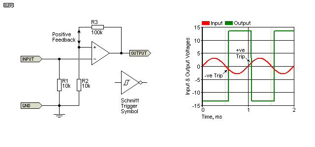
Electronic hysteresis with a comparator is much the same as a toggle switch, except it's easily controlled by component selection, and is pretty much 100% guaranteed to do exactly what you've set it up to do. You can decide how much the input voltage must change before the output changes state by selecting appropriate resistor values. Hysteresis can be added to opamps used as comparators as well as 'true' comparators. Some more examples of hysteresis are shown further below. Figure 2 (below) shows the standard arrangement used with an opamp to obtain hysteresis.
In the Figure 2 drawing, you can see that the comparator is inverting, but the +ve and -ve trip points are different. The output will swing high only when the input voltage has reached -1.3V, and it won't return low until the input has reached +1.3V. Any change that occurs between these two voltages has no effect. Without R3 (which provides the positive feedback), the output will change state at zero volts (plus or minus any input offset), but is easily influenced by noise. With a slow-moving input voltage, the positive feedback also reduces the switching time which may be important in some applications.
By varying the value of R3, you can apply more or less hysteresis. Increasing the value reduces the effect, and reducing it gives more hysteresis. If R3 is made equal to R2, the trip voltages will be half the opamp's (or comparator's) peak output voltage. For a TL07x opamp, that means roughly ±6.8V with 15V supplies. A non-inverting Schmitt trigger would have the -ve input grounded, and the input is via a series resistor (R1 is not grounded, but becomes the input resistor). The -ve input is grounded. The disadvantage of this is that fast pulses are passed through the input resistor, back into the circuit being monitored. If it's an audio circuit, this will usually cause audible distortion, especially at low levels.
All amplifiers have a slew rate that's set by the speed of the active devices, the current density (higher current means higher speed) and circuit impedances. High impedance circuits are generally slower than low impedance types, because stray capacitance has a greater influence. 10pF of stray capacitance limits a 1Megohm circuit to 16kHz (-3dB), or 16MHz if the impedance is reduced to 1k. Of course, lower impedances mean higher current, so the voltage limits for very high speed devices are generally lower than for slower circuits to limit the power dissipation.
Slew rate is simply how fast the output signal can change, usually expressed in volts per microsecond (V/µs). If the input voltage changes too quickly for the circuit (and its feedback network if applicable) to keep up, the output signal becomes limited by the slew rate. The output voltage rate of change means that a fast transient may not be detected and processed properly. With audio systems, this created a furphy called 'TID' (transient intermodulation distortion) or 'TIM' (transient intermodulation). The effects are certainly real, but almost never happen with a normal audio signal unless the designer made a fairly epic error.
Slew rate is important for comparators used in high speed processing, because if too slow, power dissipation may become excessive and/or the process simply doesn't work properly. Opamps range from a very leisurely 0.5V/ µs (µA741 for example) through 13V/ µs (TL07x) and up to several hundred volts per microsecond (or more) for some specialty devices. However, just because an opamp has a high slew rate, that doesn't mean it has a short enough response time to be useful as a fast comparator.
When a linear feedback system is pushed to the point where slew rate becomes an issue, the opamp operates open loop while the output is slew rate limited. That means that there is no feedback, so the requirements for a 'linear' system aren't met and the result is distortion. Slew rate is simply the maximum rate-of-change for the output of a device (opamp, comparator, audio power amplifier or industrial control system). Once the maximum is reached, it doesn't matter how much harder you push the input, the output can't change any faster.
It's important to understand that slew rate is not necessarily equal for positive and negative going output signals. Depending on the circuit, it's not at all uncommon to find a high slew rate for negative-going signals, but a much slower slew rate for the positive-going transition (or vice versa). The may be cases where this can be used to your advantage, although I must confess that I can't think of any  .
.
As noted above, you can use an opamp as a comparator, but compared to the 'real thing' the opamp will often be too slow. Even fast opamps are much slower than fairly ordinary comparators, and this is especially true when the opamp has a built-in compensation capacitor. The cap is used to ensure the opamp remains stable when feedback is applied, usually down to unity gain. For opamps that don't have the internal cap, there will be connections provided to allow the designer to add a compensation capacitor that's designed to maintain stability at the gain being used.
When any opamp is used with high gain, the amount of compensation is much less than needed for low (or unity) gain. By using external compensation, the circuit can be optimised, providing a higher slew rate than is available from internally compensated devices. Most externally compensated opamps are also provided with input offset null pins. These are readily available in 8 pin packages, but they include only one opamp. Any 8-pin dual opamp must be internally compensated, because there are only enough pins to provide power, inputs and outputs.
There are some dual externally compensated opamps in 14 pin packages, but they are not common. In general, if you need an uncompensated opamp, you will use a single package, but not all single opamps have provision for external compensation, so you need to make your selection carefully. The NE5534 is one example, it's a single opamp with external compensation and offset null. However (and this is why you need to check the datasheet), the NE5534 is already compensated for gains of three or more, so they aren't as fast as you might imagine. They also use clamping diodes between the two inputs, making them unsuitable in most cases.
The drawing below shows an opamp connected as a comparator, and only Rule 2 applies. When the two inputs are at exactly the same voltage, the output is indeterminate, and it will be affected by the smallest change of voltage, such as the tiny variations we get due to normal thermal noise. The transition voltage is also affected by the opamp's input transistors, which will never be 100% identical. Given that the open loop gain of many opamps is well over 100,000 (100dB), it follows that a few microvolts difference between the two inputs is all that's needed to send the output to one supply rail to the other. In datasheets, the open loop gain may be specified as V/mV, so 200V/mV indicates a gain of 200,000 (106dB).
The circuit for an opamp Schmitt trigger is shown below, along with the standard symbol for a Schmitt (the circle at the output shows it's inverting). The amount of positive feedback is set by R2 and R3. R1 is not needed if the input is DC coupled to the inverting input of the opamp, and its value is selected to suit the application. Supply voltages are not shown, but are assumed to be ±15V for the simulation.
R3 applies a small amount of positive feedback, and that provides a 'dead band' between the two trip voltages. Assuming ±15V supplies and ±14V output swing, the input has to rise to +1.27V before the output will swing high, and -1.27V before it swings low again. As long as the input is between these two values, the output won't change state, so noise (from any source) is effectively rejected. To reduce the dead band, reduce the value of R2. For example, if R2 is 1k, the hysteresis is reduced to ±138mV, or 100 ohms reduces that further, to just 14mV. Rather than reducing R2, you can increase R3 if preferred. If a bipolar transistor opamp is used, you need to account for input current when selecting the value of R3.
Note that the voltages described are the theoretical values - the input pair's differential offset voltage will affect the actual voltages. The opamp's peak-to-peak output swing also changes the trip voltages, especially when a only small amount of hysteresis is used. Some hysteresis is almost always needed if you have a slow input signal, such a long time delay. Without it, the transition between high and low states will be poorly defined and may show a large noise signal as the output changes state.
You also need to be aware that most opamps cannot swing their outputs to the full supply voltages, although some are specified for rail-to-rail output swing. Most CMOS opamps come very close, but all opamp output stages are affected by the load on the output. The datasheet is definitely your friend here (as always).
When an opamp is used as a comparator, the most important specifications for reasonable speed are the slew rate and response time, although the latter is rarely specified for opamps. In general, it's better to use a real comparator than an opamp for anything operating at more than a few kHz. Naturally, this depends on the specific application, and it's the designer's job to determine the optimum part. Not all comparators are as fast as might be required either, and that makes it harder to find the best overall compromise.
Note that the opamp Schmitt trigger can also be set up to be non-inverting. The inverting input is connected to the reference voltage (or ground), and the signal is then applied via R2. Because the current flowing through R2 is non-linear due to the positive feedback, it can couple switching transients directly to the signal source.
You also need to verify that the opamp you use does not have protective diodes across the inputs, and that there is no phase reversal with high common mode voltages (this can eliminate the TL07x series of opamps, because they do exhibit a phase reversal). Also, verify (usually by experiment as it won't be in the datasheet) that there is no interaction between opamp sections of dual or quad packages. Unless you use a rail-to-rail output opamp, it may not interface properly with TTL logic circuits or even simple transistor switches. There is (usually) no problem with CMOS logic, but it needs to be verified.

| NOTE: While the TL07x family can be used as comparators for many low speed applications, beware! These devices (along with several other opamps) suffer an output phase reversal if their common mode voltage is exceeded. You must make certain that the input voltage can never approach or exceed the supply rail voltages. Based on the TL071 datasheet info for common mode input voltage, it's claimed that the worst case maximum common mode voltage is ±11V when using ±15V supplies. Typical is said to be -12V to +15V under the same conditions. I suggest that you avoid these opamps if you need a comparator. |
A circuit that uses an opamp comparator is Project 39, which uses a µA741 opamp because speed is not an issue. There are some applications where it doesn't make sense to use a true comparator, especially for very low speed circuits. Comparators are also used in A-D (analogue to digital) converters, and countless other circuits. Many can use opamps because they don't need high speed, while others need to be as fast as possible. For example, you couldn't use an opamp in a Class-D amplifier, because they are much too slow to be able to follow the audio and reference (triangle wave) signals. Opamps can also be used for mains frequency zero crossing detectors (there's more on that topic below).
As the name suggests, a comparator is designed to compare two voltages. The output state is determined by whichever input pin is the most positive. As with opamps, there will always be an input offset and this can cause errors when low input voltages are involved. Many comparators have provision for an offset null trimpot so the error can be adjusted out. Hysteresis can be used to minimise errors caused by noise, but may cause problems with some applications. For example, if there is hysteresis designed into a Class-D modulator, it will cause distortion of the output waveform.
Comparators are used in many common applications, and Class-D amplifiers were mentioned above. A comparator has the incoming audio applied to one input, and a triangle wave on the other. The output is a rectangular waveform, with the mark-space (on-off) ratio varying depending on the audio input signal. This is shown with example waveforms in the article Class-D Amplifiers - Theory & Design. The circuit has to be fast, because the triangle reference waveform is usually over 100kHz (sometimes well over!).
Like opamps, both comparator inputs must be referred to a suitable voltage, which can be ground or some other voltage set by a voltage divider. If an input is left open, the output will be unpredictable and the circuit won't work as expected - if at all. The input signal can be capacitively coupled to the input, but you still need a resistor (commonly to the reference voltage) to ensure that the proper DC conditions exist. Also like opamps, comparators are available in single, dual and quad versions, and in various package styles.
Unlike opamps, many comparators have an open-collector output, and there isn't a transistor to pull the output high (I don't know of any that use a PNP output transistor and require a pull-down resistor, other than the discrete circuit shown below). You need to include a resistor from the output to the positive (or negative) supply. This is sometimes a nuisance, but comparators are usually used in a different way from opamps, and an open collector output is often more convenient (believe it or not).
The LM311 is an example of an open collector output comparator. There are also comparators that are designed specifically to interface to TTL ICs, and are complete with a separate 5V supply for the logic outputs (the LM361 is an example). The open collector output can also drive a relay, provided the current is less than the maximum specified (50mA for an LM311). Diode protection must be added to the relay to protect the output transistor from high voltage when the relay turns off.
Many comparator datasheets don't specify a slew rate, but tell you the propagation delay or response time instead. For example, the LM311 has a slew rate (from the graphs) of around 30V/ µs, and the response time is specified to be 200ns. There are several dependencies and conditions that affect the slew rate and response time, and I suggest that you look at the data to see some of the info. It's not particularly intuitive, so be prepared to spend some time to acquaint yourself with the terminology used.
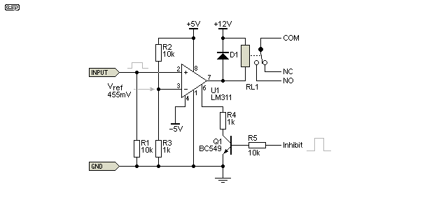
The LM311 is a fast comparator, and it has many options. As shown, the input section uses ±5V supplies, the relay is powered from +12V (referred to ground). A small positive input (456mV or more as shown) on pin 2 will activate the relay, but it can be prevented from operating by a logic signal applied to the 'Inhibit' input (this input is called 'TTL strobe' in the datasheet).
If you wanted to trigger the relay based on a negative input, it's simply a matter of reversing the input pins, so pin 2 would be returned to Vref and the input applied to pin 3 instead. This level of flexibility doesn't appear with opamps, in particular the supply options. The output is referred to a separate pin (pin 1), so the inputs and output can be referenced to different voltages. An opamp used in a circuit to achieve the same result would need many more support parts to achieve the same result. The circuit shown is adapted from the LM311 datasheet.
The datasheets for comparators can be quite confusing if you are used to reading the data for opamps, and they often have seemingly strange features. While the basic operation is similar to an opamp used open loop, there are options that you would never see for most typical opamps. There's no point trying to cover them all though, because (like opamps) there is an astonishing number of different devices, some straightforward, and others very different.
You will see comparators with facilities to change the input device bias or a 'strobe', where the output can be switched on or off with an external signal from a micro controller or other logic circuitry. As noted earlier, most have open-collector outputs, but some others have a traditional 'totem-pole' output stage similar to that used with logic ICs.
In some cases, and especially if you don't need extreme high speed, a CMOS comparator can be an excellent choice. They are typically low power (some as little as 1µA supply current), usually have extremely high gain, and will usually be fairly well behaved. A comparator such as the LMC7211-N is an example. Supply current is 7µA, and it will operate from 2.7V to 15V supplies (maximum, between supply pins). Like most CMOS ICs, the supply voltage is limited to a typical maximum of 16V, and most are only available in SMD packages. However, they are a good choice when current is limited (such as battery powered equipment) and you need to interface with other CMOS (or TTL) gates or other logic ICs.
Many comparators provide dual outputs as well as dual inputs. When dual outputs are available, they are (usually) complementary, so when one goes high, the other goes low. This provides greater flexibility when interfacing with logic, and can save the designer from having to include a separate inverter to obtain differential outputs.
If you wish to do so, it's fairly easy to make a comparator with discrete components. There's not really much point because most comparators are very reasonably priced, but building one is guaranteed to give you a better overall understanding. The circuit for a simple comparator is shown below, and as simulated it works rather well despite its simplicity. It's somewhat unconventional, in that the output transistor is PNP, while most commercial devices use an open collector NPN transistor. The rise and fall times are respectable, and response time is also fairly good. It won't beat any of the ultra-fast devices around, and obviously will occupy a great deal more PCB real estate than an IC, but it's a good learning tool.
A simplified schematic also provides some insight into the inner workings. As shown below, the output pull-down resistor (R2) connects to ground, but it can just as easily connect to any other voltage, provided it's less than the +5V supply. There's no reason that it can't be connected to the -5V supply, but a voltage varying between 0 and 5V is compatible with most logic. This flexibility extends to most IC versions as well, although most use a pull-up resistor. This is typically connected to the +ve supply, but it can connect to any (almost always positive) voltage within the ratings of the device.
To get the highest possible gain from a simple circuit, Q3 and Q4 form a current mirror as the load for the input pair. A resistor at the collector of Q1 could be used instead, but that reduces the available gain and the circuit doesn't work very well. Comparators usually have similar gain to opamps (typically between 50,000 and 200,000).
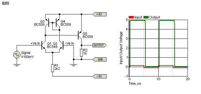
The graph shows the input signal (red) and the output (green/ blue), and you can see the small delay between the input going high or low and the output doing the same. It's obvious that it takes longer for the output to turn off (580ns to zero) than it takes to turn on (300ns to +5V). Adding D1 reduces this because it prevents Q5 from entering hard saturation. The maximum output level is reduced from 5V to about 4.5V (diode dependent). Whether you add D1 or not is a moot point, as using the circuit would be silly when it's easily outperformed by a cheap IC.
Part of the difference is due to the use of a resistor to pull down the output, but Q5 also has to leave its saturation region which creates a further delay due to the stored base charge of the transistor. This can be reduced at the expense of greater complexity. Adding a large number of extra transistors is of little consequence in an IC but has a large impact on discrete circuits. Adding a diode as a Baker clamp (D1*) reduces the turn-off delay by a worthwhile amount (up to around 500ns or 0.5μs), with a Schottky diode performing better than a 1N4148 or similar.
As simulated, response time is well below 1µs, but as seen above, it's different depending on the polarity of the input signal. Rise and fall times are 65µs and 47µs respectively, measured using the standard procedure which measures between 10% and 90%. I almost believe that part, because simulators and real life can often diverge, but they're not unreasonable figures. Is it as good as a cheap and cheerful LM311? No, and the LM311 will cost far less than the parts needed for the discrete version (the LM311 is available for well under $1, which is very hard to beat). Admittedly, the LM311 does need an output pull-up resistor in most cases, but that's true of most comparators.
Many comparator datasheets include a simplified schematic of the device, and these can be used for ideas. However, most are much more complex than you may have expected, necessary to achieve very high speed. Current sources are often shown as a symbol, rather than the actual circuit. These are easy to include in a simulation, but less so in 'real life'.
Sometimes, you need to monitor a signal to ensure that it remains within specific boundaries. A window comparator will remain off as long as the input is within the 'window' of allowable limits. A window comparator isn't a single part - it's built using two comparators, with appropriate biasing resistors or voltage references to provide the upper and lower bounds of the 'window'. Window comparators are common in industrial processes to ensure that a particular process is functioning within allowable limits.
They have also been used in alarm systems intended to detect tampering by intruders. You can also use a window comparator to ensure that an audio signal remains below the clipping level, so for a circuit operating with ±15V supplies, you may want to indicate overload should the signal exceed ±8V. The window ranges from -8V to +8V, and as long as the signal remains within these limits, the overload LED stays off.
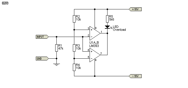
The above shows a window comparator that will provide a low output (drawing current through the LED and R5) if the input voltage goes above 2/3 Vs or below 1/3 Vs (Vs is the total supply voltage, 30V), and the circuit is similar to the comparator arrangement used in the 555 timer. In this case, the 'overload' LED will come on if the signal voltage goes above +5V or below -5V. The comparator outputs are simply joined together, something you cannot do with opamps. If power consumption is an issue, a CMOS device could be used. Some have a total current drain of around 1-2µA, but the total supply voltage is usually limited to around 16V.
To change the range where the overload LED comes on, simply change R3. For example, increasing R3 to 22k means the LED will come on if the input voltage exceeds ±7.86V (close enough to the ±8V mentioned above). You only need Ohm's law and the voltage divider formula to work out the value needed. If you need to detect that a signal has strayed by only a small amount, it may be necessary to use comparators that provide DC offset adjustment to ensure an accurate result.
Note that the drawing doesn't show supply bypass capacitors (one from each supply pin to ground), but these are essential because many comparators will oscillate if they are not included. This is especially important with very fast devices. The bypass caps should be as close to the IC as possible, and all PCB tracks to the inputs should be kept short.
To achieve the same result using a dual opamp, you would need to add 2 diodes (one at the output of each opamp) so the outputs can be added without causing the opamp outputs to draw excessive current. The open collector outputs of the comparators means that they can simply be joined, and either U1A or U1B can pull the cathode of the LED low to indicate that the window limit has been exceeded in either polarity.
Multi-level comparators can also be made using much the same principle as shown above, but with more sections in the voltage divider string and multiple comparators. This technique is used in the internal circuitry of the LM3914 (linear) and LM3915 (log) LED bargraph drivers. Equivalent circuits are shown in both datasheets, and if you need to know how to create a multi-level comparator these are a good reference.
Many of the oscillators that are commonly built using opamps will work better with a comparator. For low frequencies (less than 1kHz or so) this is of no consequence, but no normal opamp can be used as a crystal oscillator running at 10MHz or more. Comparator oscillators are limited to generating squarewave outputs. If you need a sinewave, that's a linear function, and therefore requires opamps (integrated or discrete).
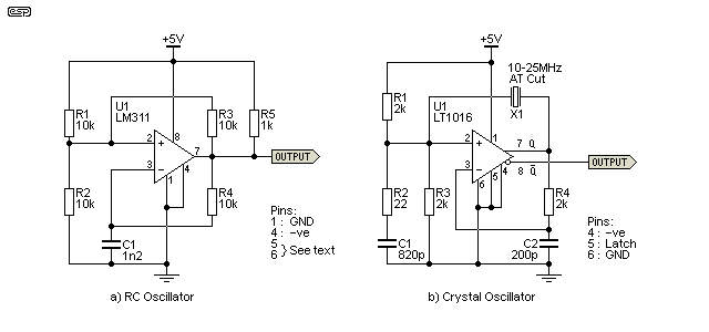
The RC oscillator is shown in almost every opamp application note ever created, and it certainly works well with most opamps up to a few kHz or so. If you use an opamp, R5 is not needed, but it is required here because the comparator has an open collector output. When built using a comparator, response can easily be extended to 1MHz using 'ordinary' comparators, but much higher frequencies are easily achieved. As shown, frequency is around 95kHz, and it can be adjusted easily by making R4 variable. The circuit is adapted from the LM311 datasheet.
The crystal oscillator shown is adapted from the LT1016 datasheet, and that can be used up to 25MHz. Such speeds are unthinkable with opamps. Some may get you to 1MHz or so (with some difficulty), but a fast comparator makes it seem easy. Both oscillators have squarewave outputs. Because some of the pins on comparators have 'odd' assignments, the various grounded pin assignments are also shown, and two unused pins are included in the listing for the LM311.
To give you an idea of how 'odd' the pin assignments can be, pins 5 & 6 on the LM311 are either for offset null or to increase the input stage current, and pin 6 can also be used as a 'strobe' input to disable the output. Naturally, only one of these extra functions can generally be used at any one time. The output can also be taken from pin 1 (normally GND) and used as an emitter follower, by tying pin 7 (output) to the positive supply and using a resistor to ground as a pull-down.
Confused? Welcome to the wonderful world of comparators.
When people think of timers, the 555 almost immediately springs to mind. This isn't unreasonable of course, because it's ideally suited to the task. The 555 timer has, at it's heart, comparators. Again, not at all unreasonable. However, not every timer needs a 555, although they are cheap, ubiquitous and work well. To learn more about the 555 timer, have a look at the 555 Timer article. However, if you wish to experiment with a comparator by itself then there's much to be gained in the knowledge department.
The voltage across a capacitor over time is determined by the capacitance and the charging current. When a resistor from a fixed supply voltage is used to charge the cap, the voltage across the resistor falls as the cap charges, reducing the charge current and producing the familiar exponential charge waveform. This is visible in the graph below (VC1). This class of timer is not capable of great accuracy, but that's not always necessary. Repeatability is usually better than you might expect, provided the supply voltage is regulated.
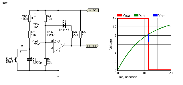
The timer is started by pressing the button. This discharges C1 (via R1 which limits the capacitor discharge current), and timing starts when the button is released. This general class of timer is usable for medium time delays of up to a few minutes. The delay time can be varied by means of the pot (VR1). The graph shows the voltages when VR1 is at minimum resistance, and delay time is increased with increasing pot resistance.
Press the button, C1 is discharged, and the output of U1 goes from low to high. When the button is released, C1 charges until its voltage reaches the 8.25V threshold (Vref). Once the threshold is reached, the output goes low again, indicating that the selected time has elapsed. Note the diode in series with R6 - that applies positive feedback to provide unidirectional hysteresis - it only works as the output falls from high to low, but has no effect on the trip voltage set by the voltage divider (R3, R4). When the output falls low, the reference voltage is reduced from 8.25V to around 6.5V (blue trace). This ensures a fast and unambiguous output transition.
With the values shown, the time delay is from 11.5 seconds up to about 125 seconds by adjusting VR1 (maximum resistance gives maximum time delay). Be aware that this circuit is intended as an example only, and is not a recommended design. The most obvious problem is that the time can be extended simply by keeping the button pressed, so it can't be relied upon if an absolutely reliable delay is needed. It's also a bad idea to use electrolytic caps in a timing circuit, because they have a large capacitance tolerance and aren't especially stable with temperature. There are other problems too, so please use this as an example so you can understand the basic function, rather than imagining it's necessarily a usable design as shown.
The circuit shown will work equally well with an opamp or a comparator, but the latter has the advantage of a full rail-to-rail output, limited only by the load on the output. This should be no less than 10 times the value of R5 to minimise errors. If the load current is too great (relative to the current through R5), the circuit may malfunction.
There is one use for this style of timer - a delayed switch for lighting. As long as the switch is closed, the light will be on. When the switch is turned off, the light will remain on for the preset delay time, and turns off when the delay has expired. Yes, I know it can be done more simply, but this is an example to demonstrate that even apparently 'flawed' circuits often have very valid uses.
There are many places where zero crossing detectors are used. Mains phase control switching is one very common usage, as a zero crossing detector is needed to detect the beginning of each cycle. Another is where an audio signal is required to switch 'silently', so switching takes place when the audio signal passes through zero. Zero crossing detectors are also used for signal generating applications, such as tone burst generators. Comparators make very good zero crossing detectors, and the circuit shown in Figure 2 is one way to do it.
The amount of hysteresis needed is very low (depending on the signal level), or you can 'cheat', and use an amplifier in front of the comparator, as shown next. It doesn't matter if the amplifier stage clips (in fact it's better if it does), because we are interested only in the period where the input voltage is at (or close to) zero. The output pulse frequency from the type of detector shown is double the input frequency, because there is one pulse for every zero crossing, so two per input cycle.
A disadvantage of comparators is that they will usually produce a positive output as the signal passes through zero from negative to positive, and a negative signal for the other half cycle. This means that additional processing is needed to provide (say) positive pulses for each crossing, regardless of the signal polarity. If you need a zero crossing detector that produces only positive pulses each time the input passes through zero, you could use something like the circuit shown below.
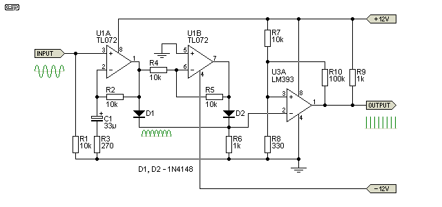
The first stage amplifies the voltage (x38), and along with the next stage (a unity gain inverter) outputs a full-wave rectified output. As the input signal passes through zero, the output from the rectifier is also zero, and this is detected by the comparator, which produces a positive pulse. The width of the pulse is largely determined by the amount of gain in the first stage and the input frequency, and with the values shown provides 8.5µs pulses with a 2V p-p sinewave input signal at 1kHz (less than 0.1% duty cycle). The pulse width can be reduced to give a lower duty cycle (and reduce the pulse width) by increasing the gain of U1A, which provides a better resolution of the true zero crossing point. It will be necessary to use opamps that provide DC offset adjustment if very high gain is used. C1 is used to minimise offset for less critical applications.
The reference voltage at the +ve input of U3 is nominally about 380mV, rising to 420mV when the output is high. This isn't much hysteresis, but it's sufficient to ensure clean transitions at each zero crossing point. More hysteresis can be used (and/ or the reference voltage increased) by increasing the value of R8. This will also make the pulses wider, so the gain of U1A can be increased to compensate.
The circuit is well behaved and very flexible, and can easily be changed to suit your specific needs. It's more complex than most that you'll see on the Net, but it has the advantage of being easily adjusted, and it produces a positive pulse at each zero crossing. If greater speed is needed, use faster opamps and a faster comparator. Note that supply bypass caps are essential, but are not shown for clarity. Note that this circuit is not intended to be used with mains voltages!
For more ideas on zero crossing detectors in general, see AN005 - Zero Crossing Detectors on the ESP website.
As with most of the ESP articles, this is simply an introduction to the subject. Manufacturer datasheets are usually one of the best places to start if you want to know more, and where available, application notes can provide you with a great deal of additional info, and often provide specific examples for many different arrangements. Naturally, they reference only that maker's part(s), but you can often substitute other devices to increase performance or reduce cost.
In the audio field, there isn't usually a great demand for 'true' comparators, because the signals of interest are almost always comparatively slow. A-D converters and Class-D modulators are another matter of course, but these are most commonly IC based, and all the required processing is usually within the IC itself. In some cases, the flexibility of comparators makes them a better choice than a circuit using opamps, particularly for overload indicators and similar circuits, but the speed of even 'slow' comparators is such that it's easy for them to inject noise with switching transients.
Even opamps used as comparators can easily produce switching transients, and it's generally a good idea to provide isolation of the power supply, by using ferrite beads or low value resistors for example, and with separate decoupling capacitors. The isolation is needed to prevent fast transients from affecting the audio circuits. Careful attention is also needed for the grounding arrangements. A 'shared' ground is usually a recipe for unwanted interference, so you need to work out a plan to make sure that ground currents are separated.
As should be obvious, comparators are very different from opamps, and while they are far more flexible, they are also a lot less forgiving. Most opamps specify their short-circuit period as 'indefinite', but many comparators either can't tolerate a shorted output, or can do so for a limited time only (some specify 10 seconds, but even that is a risk). Supply bypassing is critical with any high speed comparator (much more so than opamps), and PCB layout has to be just right or you get oscillation as the output transitions from one state to the other.
If you intend to use comparators in a project, you must consult the datasheet and/ or any available application notes, because you need to know what precautions are necessary to ensure reliable operation. Their greatest advantage (speed) is also the property that makes them cantankerous if everything isn't to the liking of the IC.
The references shown below are easily found on the Net, and some devices are available from multiple sources (although TI now owns National Semiconductor). There are literally hundreds (perhaps thousands) of different devices from many manufacturers, and it would not be practical to even try to provide examples and references to them all. You can also look at Maxim, ON Semiconductor, Intersil, Toshiba, Analog Devices, ST Microelectronics - the list goes on. You can get comparators using bipolar transistors or CMOS technology, fast and slow, micro-power, etc., so there's definitely a suitable device for every occasion.
Note: The inclusion (or non-inclusion) of any manufacturer does not imply any preference or otherwise on my part, nor does it indicate any connection whatsoever to those listed. The manufacturer references shown are simply to assist the reader, and are listed for no other purpose.
| Main Index
Articles Index
|