

|
| Elliott Sound Products | Oscilloscopes |
 Main Index
 Articles Index
One of the most useful pieces of test equipment for anyone involved in design, repair or even hobbyist interests is an oscilloscope. Modern digital sampling scopes are available for surprisingly little, but they have facilities that were unheard of only a few years ago. It's often thought that only professionals need an oscilloscope, but that's not the case at all. There are some things that simply can't be resolved any other way.
For many applications, an 'olde worlde' analogue CRO (cathode ray oscilloscope) is actually a better choice, but it's now getting hard to find them new, and a second hand one may or may not be worth what you pay. It's no use to anyone if it's faulty, because most repairs will require the use of ... an oscilloscope. For anyone who needs to see what waveforms look like, nothing else will do. When I'm working on something (whether a repair or a new design), the oscilloscope is one of the first instruments to be turned on, and it's rare to find a situation where the scope doesn't tell you what you need to know about something in far greater detail than you can ever get with a multimeter.
Oscilloscopes were first developed in the early 20th century [ 1 ], and were refined over the years to become one of the most popular pieces of test gear ever developed. Many different manufacturers have made oscilloscopes (which used to be known as a 'CRO' in Australia & Britain, or a 'scope' in the US), and the designs have been refined to the point where they are now available as small handheld units that exceed the performance of full sized bench (or trolley) units from 40-odd years ago. Trolleys were quite common many years ago, because decent oscilloscopes were very expensive, so a large workshop may only have had one or two oscilloscopes that were wheeled from one workbench to another as needed.
It's hard to go past the paper published by Tektronix [ 2 ] for a good overview and a great deal of in-depth material as well. Although it (predictably) shows Tektronix scopes throughout the paper, the principles are mostly unchanged with other instruments. While much of the material is intended for the more advanced user, there's also a lot of good, basic information that will help your understanding.
The oscilloscope is one of the few pieces of test equipment that has a familiar look and feel, regardless of the maker. While some parts of the front panel will be laid out slightly differently, there is never enough variation to flummox anyone who is even passably familiar with scopes and how to use them. The layout and control conventions used are logical and sensible - there is no need to change something that works close to perfectly with almost every instrument made.
This is not to say that all scopes adhere to the conventions. The Philips PM3382A (a combination analogue/ digital scope shown below) is one that doesn't use the traditional rotary controls for the vertical or horizontal controls, but uses up/down buttons instead. It's quite functional, but nowhere near as easy to use as the rotary switches used on nearly all other instruments. However, the controls are in the usual places, and rotary controls are still used for vertical positioning.
You will usually see the axes of an oscilloscope referred to as 'X' (horizontal) and 'Y' (vertical). The timebase feeds the X-axis and causes the beam (or spot) to traverse the screen linearly from left to right. The Y-axis handles the signal, and this deflects the spot up and down in sympathy with the signal itself. As a result, the wave shape is shown on the screen, and if it's well within the scope's bandwidth, should be an accurate representation of the incoming signal. This occurs regardless of the complexity (or otherwise) of the waveform if the instrument is calibrated.
Some analogue scopes have an additional axis - 'Z'. This allows the intensity of the spot to be varied as it traverses the screen. With some external electronics, an analogue scope with a Z-axis input can display an almost perfect monochrome TV picture - probably better than a TV set, because the linearity is better. Most digital scopes don't have this feature, although intensity modulation is available on some more advanced scopes that have (fairly recently) become available.
This article is not all about how to use an oscilloscope, as that information is in the user guide and is specific to the scope brand and model. There are usage guidelines and some useful hints and tips that may be missing elsewhere. The main aim is to provide info on the basic functions and help readers to understand what oscilloscopes are used for, and why. It may seem obvious, but there's a lot more to any scope than simply looking at a waveform.
Here are some example photos of oscilloscopes. These should not be considered an endorsement or otherwise of the brands and models shown - they are simply representative of several units with some reasonable age differences to give some perspective. Click on any image to see a 'super sized' photo with more detail. (Each photo opens in a new window.)
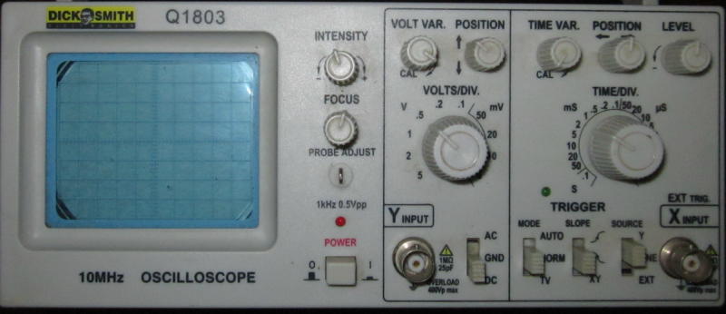
Figure 1 - Dick Smith Q1803 (Single Channel, Analogue)
This is the most basic type of oscilloscope, and has a rather limited 10MHz bandwidth. This is (just) enough for audio, but is of little use for anything much faster. It has a single channel, with a range from 5mV/ division up to 5V/ division. Higher voltages require an attenuator probe. While this type of CRO was 'cheap' in its day, compared to what you get today for not much more, it was not a bargain. This scope was bought on special, and often goes with me if I have to travel somewhere (and run tests on 'stuff'), as it's fairly small and adequate for the purposes it gets used for (which doesn't happen very often these days).
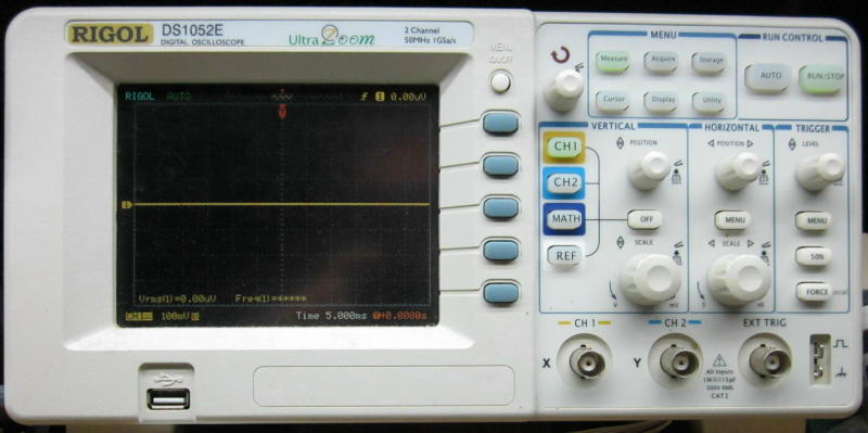
Figure 2 - Rigol DS1052E (Dual Channel, Digital)
The Rigol was extremely popular a few years ago, and was one of the first affordable digital scopes with a colour display. There was a period when they were sold directly from China that made them far cheaper than anything else at the time, and they were snapped up as a bargain all over the world. It features FFT, can display peak, average and RMS values for the input waveform, and has many other useful features. The use of a single set of controls for both channels is really annoying, and although it can save the displayed waveform to a USB flash drive, it requires several menu options and button presses. Traces from this scope are shown in many ESP articles.
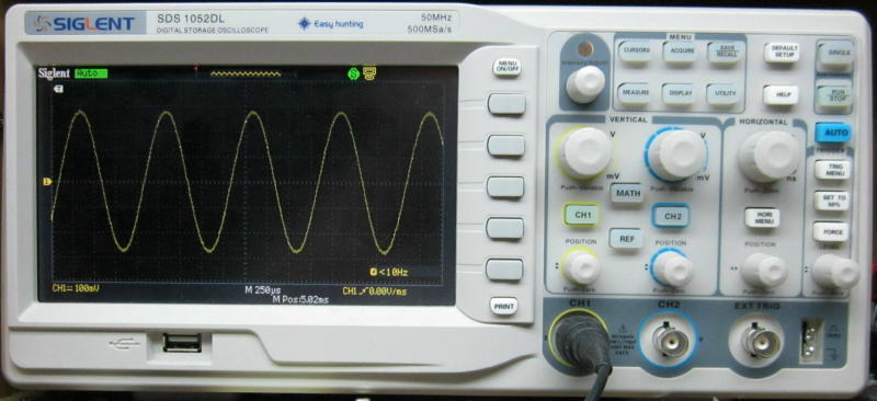
Figure 3 - Siglent DS1052DL (Dual Channel, Digital)
Having a wider screen and simpler waveform save functions makes this an easy scope to use, but its FFT capabilities are not as good as the Rigol shown above. The wide screen (18 divisions) is nice, but not essential. Having separate controls for each input is much more convenient than a single set as seen above. An entire suite of measurements can be brought up simply by pressing the 'Measure' button. This scope is available with several different brand names - Siglent is (apparently) the original manufacturer, but rebrands the scopes for other suppliers. The scope is shown displaying a 1kHz sinewave of about 280mV peak (198mV RMS). The timebase is set to 250µs/ division.

Figure 4 - Philips PM3382A (4-Channel, Analogue / Digital)
This scope is an odd-ball in many respects. It's quite capable, but has a very limited sampling frequency (200MS/s) and can only be used to 100MHz in analogue mode. Note the use of up/down buttons for input sensitivity and timebase - a major departure from convention. It's a 4-channel scope, and this can be useful, although 2 channels is enough for most work. The display is on a CRT (cathode ray tube) for both analogue and digital modes. It has a very good FFT function (in digital mode) that's sharper than either of the digital scopes shown above. This scope also features a movable cursor and the position/ frequency and amplitude are shown as it's moved across the display.
Although it has 4 channels, the 3rd and 4th channels only have two sensitivity settings ... 100mV/ division and 500mV/ division. All channels can be used simultaneously, but only one can be used as the trigger source. The extra channels would mainly be used to look at digital signals because of their limited voltage ranges. It has an inbuilt auto-calibration feature that seems to be very comprehensive (it should be, as it takes 4 minutes to complete).
There are also USB oscilloscopes that are the genuine article, meaning they are true scopes and not just a modified sound card. Most are available at up to 100MHz bandwidth, and quite a few include an arbitrary waveform generator that can create (or re-create) almost any waveform desired. They use a PC for control and display, so (at least in theory) they are lower cost than complete instruments. This is not necessarily the case though, as comparing prices indicates that you usually get more for your money with a 'traditional' digital oscilloscope.
The range of functions is often greater though, because the PC can be used to provide more processing power than you get with a stand-alone instrument. Because all control is from the PC, the 'look and feel' is different from a normal scope, and functions are accessed using the keyboard or mouse instead of rotary controls and push buttons. You can't expect that they will all be fairly similar in terms of layout, because the entire user interface is software controlled. Some can be frustrating to use due to non-standard controls, and sometimes decidedly non-intuitive methods to modify the functions.
Scopes are available to handle input signals from a few millivolts to hundreds of volts (usually with HV attenuator probes), and most (all 'modern' units less than 50 years old) can handle signals down to DC. The most important specification (and the one that has the greatest influence on price) is the bandwidth. 10MHz used to be common for 'hobbyist' scopes, many were around 20MHz, and serious test gear extended to 50 - 100MHz or more. Now, it's common to find scopes that can handle over 1GHz, albeit at considerable cost.
Less than 20MHz is not worth the effort for most tasks, and >50MHz scopes are now both readily available and reasonably priced. Few people will need 1GHz or more, but if you are involved in RF (radio frequency) or high speed digital work the extra bandwidth is essential because so much of the RF spectrum is now above 100MHz, as are digital communication systems. The bandwidth refers to the frequency where the sensitivity has fallen by 3dB, so a trace that would occupy exactly 7 divisions at a low frequency will show 5 divisions at the maximum (-3dB) frequency ... and this is a hint as to how you can use a scope to measure the -3dB frequency of the equipment under test. If the level and screen position of the trace is set for 7 divisions at a mid frequency, the -3dB frequency is the point where the waveform occupies 5 divisions. (That's actually -2.92dB if you are picky, but it's usually close enough.)
Above the rated maximum frequency, the signal doesn't 'magically' disappear, but it rolls of at ~6dB/ octave above the -3dB frequency. A 50mHz scope can usually still display a 100MHz signal, but not at the correct amplitude or waveform (which is modified by the frequency rolloff).
The conventions of oscilloscope controls are well established, and manufacturers use the same nomenclature and a familiar layout that has been in general use since the 1950s. Many instruments have additional controls, and some will be menu driven (for digital types). Scopes generally look complex to the uninitiated, but they are very logically laid out and it shouldn't take even a novice long to be able to display basic waveforms.
The exact control set depends on the instrument, but most oscilloscopes have a familiar 'look and feel' to the controls (Figure 4 above is a notable & rare exception). The speed of the vertical amplifier of the instrument is referred to as its bandwidth, and there is a timebase control that sets the sweep speed. This even applies to digital scopes that don't have a sweep as such, because the data are presented on a digital display.
Oscilloscopes are available with from 2 to 4 signal channels, although there are (or were) some budget units that are single channel as seen in Figure 1 above. There are also units with more than 4 channels, but they are primarily 'logic analysers' rather than conventional oscilloscopes. Combined systems are also available, with 2 or 4 analogue channels and 16 or more logic channels. The difference is that an analogue input has variable sensitivity, from perhaps 2mV/ division up to 50V/ division (or more with specialised probes). The digital channels are typically designed for a maximum input level of 5V and have no (or minimal) variable gain.
The calibrated controls on oscilloscopes were standardised many years ago to use a 1-2-5 sequence. Vertical (signal) and horizontal (timebase) controls follow this sequence across their range. For example, you may have a vertical sensitivity control that follows the sequence of 5mV, 10mV, 20mV, 50mV, 100mV, 200mV ... (etc.). The timebase may have a sweep time of 10µs, 20µs, 50µs, 100µs, 200µs per division ... (etc.). Voltages and times are always per division, with each division being the size of each graticule marking. Most 'standard' scopes have 10-12 horizontal divisions and 8 vertical divisions, but newer 'wide screen' types have more horizontal divisions (18 for the Siglent shown above).
Note that all figures for sweep speed and sensitivity are per division, and not full screen. This has been standard for many years, and it's important that this is understood. By measuring the number of divisions (or par thereof) and using the settings details, you can measure the actual voltage and/ or periodic time of the waveform. For example, if a waveform occupies exactly 5 vertical divisions at 20mV/ div, the peak to peak voltage is 100mV (50mV peak, or 35.4mV RMS). If the waveform completes a full cycle in 5 divisions at 100µs/ div, the period is 500µs and the frequency is 1/period = 2kHz.
All oscilloscopes have a range of standardised controls. These are found on everything from the most basic hobbyist scopes right through to the most expensive lab equipment, and there are few exceptions. There used to be some extremely basic scopes that didn't have a calibrated vertical amplifier or timebase, but these are next to useless for any serious measurements. Very early scopes (from the 1930s) often lacked calibration, but were the only way that radar systems could be examined in any real detail. Calibration is now standard for even the most basic types. The standard features/ controls are ...
Most of the above are pretty much self-explanatory, but triggering is something that catches some people out. It's often necessary to set the triggering system to only act on a rising (or falling) part of the waveform, and in some cases the trigger level needs to be placed on a specific part of the waveform to get a stable display. Trigger systems may also offer TV (so the scope can lock onto a TV composite video waveform), mains (the local mains frequency), or LF / HF reject to stop the timebase from triggering on low or high frequency signals. Many scopes also feature a 'hold-off' control that delays the start of a sweep until a trigger event is detected.
Depending on the oscilloscope, there will also be a number of additional controls. For digital scopes, the list is potentially enormous, so only the most common are described next. With digital scopes, the menu system(s) can be used to access everything from automated self-test routines to saving the displayed waveform to a flash drive or sending it to a printer. Some of the features may be used only rarely, and to assist the user, help screens are available for many (perhaps all) of the features offered.
The most common additional controls are shown below. As noted, some are only found on analogue (CRT based) oscilloscopes, and others are normally only found on digital scopes. There are also hybrid scopes - they aren't common, but they have a CRT for the display, but allow either digital or analogue operation, depending on the requirements for the measurements being taken. These have all but disappeared, but were very expensive when they became available about 20 years ago (at the time of writing).
Most digital scopes are largely menu driven for functions that are over and above those shown above. One very useful additional feature is FFT (Fast Fourier Transform) allowing the user to see information in the frequency domain - an oscilloscope is intended to display time related information (the time domain). Before the advent of low-cost digital scopes, the only way to work in the frequency domain was to use a spectrum analyser - these are expensive, even today. Although the FFT function is useful, it does not mean that a spectrum analyser isn't necessary for precision RF work, because the scope is not optimised for frequency domain measurements.
Other common functions include the ability to invert one channel, sum (add) channels, or use the scope in 'XY' mode, where the timebase is switched out and the second channel is used to provide horizontal deflection. Many scopes also have provision for an external timebase. It's common that some of the features will never be used by many users, but the cost to include them is small, and if they are omitted there will be buyers who'll simply look elsewhere ... even if they won't use the feature!
One feature that was common on analogue scopes was 'delayed sweep'. I've worked with many experienced service techs over the years who never figured out how to use delayed sweep (or why they would want to), but it was an extremely useful feature if you happened to be looking at waveforms with fast rise times - especially if the waveform was complex. By highlighting a small range of the horizontal display, it could be expanded by means of a second (much faster) timebase that only worked over a portion of the waveform.
The delayed sweep isn't needed with a digital scope, because the capture can be stopped and the entire trace expanded so that extreme detail can be seen. Note that this only applies when the sampling rate is fast enough to capture the high speed event(s) you wish to examine.
The basic specifications that you will see may be along the following lines for a fairly typical oscilloscope ...
Parameter Value Vertical Channels 2 Vertical sensitivity 2mV/div - 10V/div Maximum Input Voltage 400V Peak Bandwidth 60 MHz Rise Time <7ns Resolution 8 bit Sampling Rate 1 GS/s (1,000M samples/ second) - Digital only Time base 10ns/div - 5s/div Input Impedance 1 MΩ ±2% || 13pF ±3pF Trigger Source Ch 1, Ch 2, External, TV, Line (mains frequency)
This looks comprehensive, but it isn't really enough for a potential buyer to see whether the scope will suit his/her needs. There are many other facilities that are usually available with digital scopes, some of which are very useful, and others less so. One critical part of any oscilloscope is its triggering ability. Triggering is used to synchronise the sweep to the waveform being measured so the trace is stable. Any scope that can't trigger reliably on common waveforms is next to useless, but fortunately there are very few that fall short. Better units will have had a great deal more time spent on development of the triggering circuitry to ensure a stable display with complex waveforms.
Many scopes feature an external trigger (aka synchronising or 'sync') input. This can be very useful when trying to look at a signal that's buried in noise, or if there are regular (non-harmonic) interruptions to the signal. For example, if one is using a tone-burst generator, the use of external trigger is almost essential, with the timebase triggered from the tone burst generator's sync output. It's provided for exactly this purpose.
External triggering is also very handy if you are looking at the distortion residual from an amplifier. The scope is triggered from the signal generator, so harmonics, noise, and other disturbances don't cause false triggering which makes the residual waveform very difficult to see clearly.
The most common input impedance for vertical channels (signal) is 1MΩ in parallel with some small capacitance, typically between 15-25pF. The capacitance is mainly 'incidental', in that it's not primarily a physical capacitor, but is due to the natural capacitance of input BNC connectors, attenuators and amplifiers (plus the 'stray' capacitance of wiring or PCB traces). However, in some cases a small capacitor is added, because oscilloscopes are expected to have an input capacitance that falls within the range of 15-25pF. Too much or too little would mean that 3rd party attenuator probes would not equalise properly (this is covered in more detail below).
In some cases, an optional 50Ω input impedance is provided, specifically for RF applications where 50 ohms is a very common impedance. This allows the scope to act as a terminating load so that input cables don't cause frequency response errors. See the article on Coaxial Cables for more on this subject if you are interested.
It's important to understand that an oscilloscope needs a wider bandwidth than expected if you wish to view pulse waveforms. A 50Mhz scope will give a passable display for 10MHz pulse or rectangular waveforms where it can display up to the 5th harmonic (just), but at 50MHz it can show only a very different waveform from that actually supplied - but you may be blissfully unaware of this. You may see this referred to as the "five times rule", and it even applies to sinewaves if an accurate amplitude measurement is required. Even with a 10MHz input sinewave, the level will be 0.2dB down with a 50MHz scope.
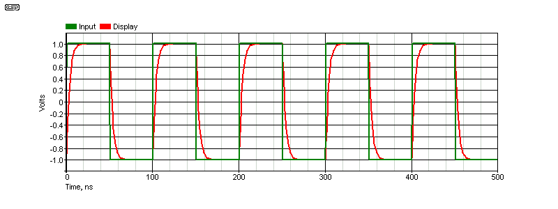
Figure 5 - 10MHz Waveform With 50MHz Oscilloscope
The above shows how a rectangular or pulse waveform will be distorted. There is clear evidence that the bandwidth isn't wide enough, and consequently the risetime isn't fast enough for the waveform to be displayed properly. The risetime of the input signal is well under 1ns, but the scope displays it as 7ns - that's a big discrepancy, even when the five times rule is used. For pulse waveforms, the scope needs to be at least 10 times faster than the highest frequency to be measured, and even then it will still distort the waveform.
It's not until the scope is around 50 times faster than the waveform that it can display a reasonably accurate pulse waveform if the rise and fall times are particularly fast. It should now be obvious just how limited a low speed scope really is, and why I suggested earlier that a 10MHz scope is only just adequate for audio. Note that rise and fall times are always measured between 10% and 90% of the peak amplitude.
The basics of an oscilloscope are much the same whether it's analogue or digital. The internal workings are very different of course, but the end result is the same. The first thing in the signal chain is the vertical attenuator(s) and amplifier(s). Amplification is needed when the signal to be measured is too small to either deflect the beam of get a decent digital representation of the signal, and attenuation is necessary to allow higher voltages to be displayed. The vertical amplifiers and attenuators determine the bandwidth, and will usually have a response extending from DC to at least 10MHz, more commonly 50 to 100MHz, and up to several GHz for very high speed scopes. Early valve oscilloscopes were often AC only because it's difficult to make a DC coupled valve stage, especially one with high gain and low drift (time and temperature).
Oscilloscopes (with the exception of some 'pseudo scopes' that are little better than a PC sound card) use BNC connectors for all inputs, and have done so since the late 1950s or early 1960s. See Connectors in the article about coaxial cables for more. Earlier scopes often used type 'N' connectors, but these were replaced when the BNC became available, as it's a much smaller connector but with no sacrifice in reliability. Scopes invariably use 50Ω BNC connectors, even though they have a 1MΩ input impedance. However, as noted elsewhere, some scopes offer a 50Ω input impedance as an option (usually switchable).
The gain is switched using a 1-2-5 sequence, but most scopes also allow a fine adjustment which is uncalibrated. Some will display an indicator (such as 'UNCAL') to warn the user that the display is no longer calibrated, so accurate voltage readings aren't possible. This can be useful for some measurements where the absolute value is unimportant, but a relative reading gives you the information you need.
Most modern oscilloscopes provide at least two input channels (dual trace). This was also common with better analogue scopes as well, but other than a very few highly specialised units, there is actually only one electron beam. There are two options for dual beam analogue scopes - 'chopped' and 'alternate'. When the beam is chopped, it's divided into very small segments (the frequency is typically around 250kHz) as the timebase causes the spot to traverse the screen. One set of 'segments' is used to display the data from input #1, and the other set handles input #2. The beam is blanked as it switches from one to the other so it looks like there are two completely independent traces. Each 'trace' can be repositioned on the screen without affecting the other.
This trick only works at relatively low frequencies though, because as the timebase speed is increased, there's a finite limit to how quickly the beam can be moved from one trace to the other. That's where the 'alternate' setting comes in. One complete left to right sweep is for Channel #1, and the next is for channel #2. Again, the user sees two independent traces. If the timebase speed is reduced too far, you can see that the traces are indeed alternate. One trace is drawn across the screen, and when that completes, the second channel is displayed.
There is no requirement for 'chopped' and 'alternate' modes for a digital scope because the signals are multiplexed by the ADC and any number of traces can be drawn. However, most low cost scopes (as well as some professional models) cannot provide the full claimed sample rate on both (or all) channels at once. The effective sampling rate is halved when two channels are in use, and halved again if 4 channels are active.
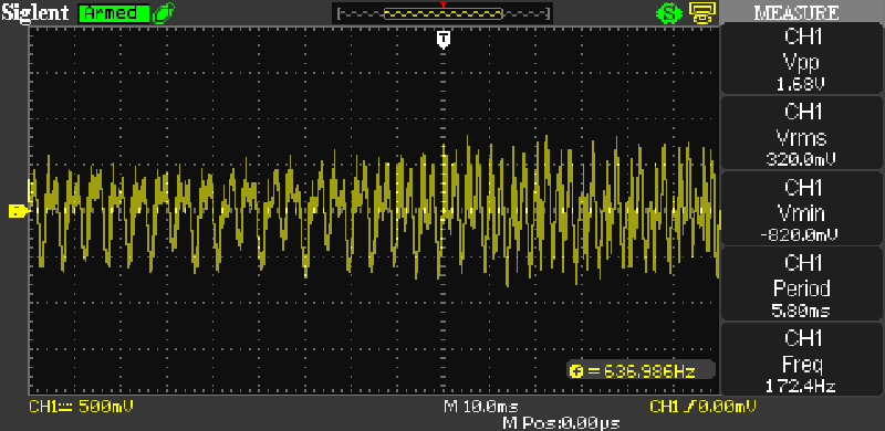
Figure 6 - Siglent Scope Showing Measurements
Some of the measurement capabilities of a digital scope are shown above. You can see the measurement panel on the right, and it shows that the waveform is 1.68V peak-peak, 320mV RMS, the minimum voltage detected (not useful in this case), and the period and frequency of the waveform. These are also not useful because it's a fragment of speech captured from the radio, but the scope tried to make sense of it anyway. The period of 5.8ms corresponds to the frequency displayed (172.4Hz). Note that the normal on-screen frequency measurement is quite different from that in the measurement panel. This is a clear indication that the reading can't be trusted (they are normally the same).
All (other than old valve based) oscilloscopes have provision to set the inputs for AC or DC coupling, with most also providing a ground setting. The latter isn't useful for looking at waveforms (because the input stage of the amplifier is grounded), but it can let you 'find' the trace if it's sent off-scale because the input voltage is too great. Note that the input BNC connector pin is not grounded, as that would create a short at the device being tested. Some (analogue) scopes even have a 'beam finder' that reduces the X and Y sensitivities to some low value that lets you see where the beam has been deflected to - it's not always obvious! When AC coupled, the low frequency response is usually between 1.5Hz and 7Hz (-3dB frequency), so measurements below 20Hz will have a significant amplitude error.
Most digital scopes have an 'auto-set' feature - press the button, and the scope will set the gain and timebase to display the waveform so it nicely fills the screen. This can be especially useful for beginners, because using an oscilloscope is as much an art as a science. Someone who knows his/her instrument well will be able to set it up to get the exact display desired in moments, and an observer won't have time to see what was done because it all happens so quickly. A beginner or infrequent user may take several minutes to achieve the same result, but perhaps not knowing exactly why controls are set the way they end up.
It's important to understand that an analogue oscilloscope does not use the same system as a TV or computer monitor CRT. These draw the image by continuously scanning the screen from the top left to the bottom right, and images are drawn by modulating the intensity of the electron beam. An oscilloscope draws one line from left to right, and that line is deflected vertically by the input signal.
Because the internals of a digital scope are pretty much inscrutable, it makes more sense to examine the way an analogue scope works. A digital scope is designed to emulate the analogue functions, but most of the work is done by one or more ASICs (application specific ICs) and/ or microcontrollers and/ or microprocessors, and functions are controlled by software.
In contrast, analogue scopes all work in a similar way, and are fairly traditional in terms of circuitry. There are as many different circuits as there are oscilloscopes, but the basic ideas have been with us since the days of valves (vacuum tubes). Transistors and ICs made scopes far more reliable, provided higher speed, and made it easy to add functions that would have been too complex with valves.
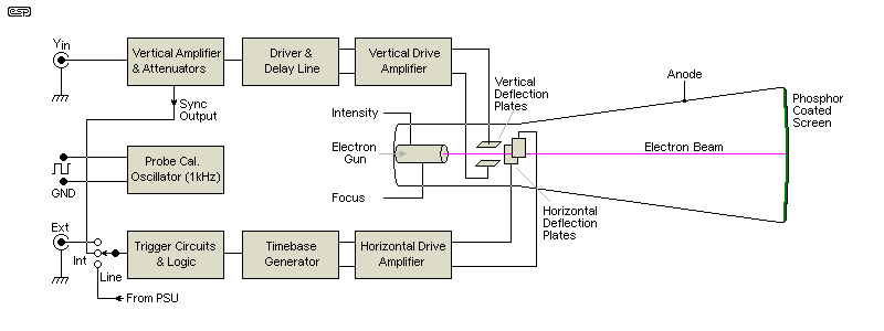
Figure 7 - Block Diagram Of Basic Oscilloscope
A simplified block diagram is shown above, reduced to the minimum for ease of understanding. The various blocks are shown below, starting from the output - the cathode ray tube. Power supplies are not included, and a typical scope may have 5 or 6 separate voltages, ranging from high voltage supplies (2kV to 8kV or more, positive and/ or negative), medium voltage supplies (200V or so), plus the voltages for analogue sections (perhaps ±8 to 15V), and often a +5V supply for logic ICs that are commonly found in triggering circuits and beam switching (for dual beam scopes).
The above only shows a single vertical (Y) channel, but analogue scopes can have from 2 to 4 channels. Adding channels makes the overall system much more complex, because there has to be provision to use the same electron beam to display two (or more) channels, and the trigger circuitry has to be able to be switched from one channel to the other. Most scopes only allow a single trigger source. Digital scopes may have additional inputs (16 is common) for logic analysis. When provided, these usually have a limited voltage range with minimal controls. Further discussion of logic analysers is outside the scope of this article.
Normally, we'd start at the input, but in this case it's easier to start from the output - the CRT itself. The CRT is a (large) vacuum tube, and is vaguely similar to the tubes used in TV sets. However, deflection is not magnetic as it is (was) with TV, but is electrostatic. An electron beam is generated by the electron 'gun' at the far end of the tube, passes through accelerating and focusing electrodes, and then through the gaps between the deflection plates. A negative voltage on a deflection plate will repel the electrons in the beam, and a positive attracts the electrons. This allows the circuits to deflect the beam up and down, left and right.
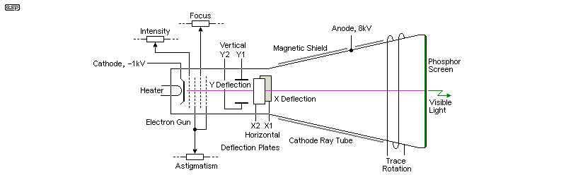
Figure 8 - Cathode Ray Tube Basics
The essential parts of a CRT are shown above. Focussing and astigmatism and other elements are traditionally shown as grids (as found in a normal valve), but in reality they are often specially shaped plates or sub-assemblies. Most voltages are not shown because they vary widely depending on the CRT itself, and voltages on the various elements are variable to adjust the characteristics of the spot. Oscilloscope tubes are much longer than a TV tube (with the same faceplate size) because they use electrostatic deflection which is less effective than magnetic deflection, but much more linear. The long tube also means that the distance from the centre to the extremities of the tube face changes very little, ensuring good focus at all points on the tube face.
In many of the better analogue scopes, the graticule is etched into the inside of the glass faceplate so there is no parallax error. The phosphor coating on the inside of the faceplate fluoresces when struck by the electron beam, and this provides the visible trace. The trace intensity is varied by changing the beam current. By modulating the grid that controls beam current, the trace can be turned off during the retrace (when the spot returns to the left from the right of the screen). Intensity modulation can also be applied by the Z-axis if provided.
The power supply for a CRT based scope requires multiple voltages. The acceleration potential (negative) is applied to the cathode, although some tubes include an additional acceleration electrode that carries a high positive voltage. This varies, but 8kV or so is common on many Tektronix scopes. Another feature that you will see on most analogue scopes is a 'trace rotation' control. The earth's magnetic field affects the trace, and the rotation control allows it to be repositioned so it's perfectly in line with the graticule. Some cheap scopes (such as the one shown in Figure 1) rotate the tube itself. Better CRT scopes have a magnetic screen around the tube, generally MuMetal, although it's likely to be thin steel in cheaper versions. This minimises interference to the beam's deflection from nearby transformers in other equipment.
The graticule often greatly underestimated as a tool for measurements. It is there so that the essential characteristics of a waveform can be determined. Since each vertical division corresponds to a known voltage and each horizontal division is a known time period, the periodic time of a waveform can be determined easily, and frequency is simply 1/time. For example, a waveform that completes a cycle in 1.2ms has a frequency of 833.3Hz. When read from an oscilloscope, voltages are commonly stated as peak-to-peak, because that's what is most easily measured from the graticule. This is often all you need, and in some cases is exactly what you need. To see that an opamp preamp (for example) can provide 25V p-p indicates that it can drive any amplifier known, but if the output swings to (say) +13V and -2V at the onset of clipping, this should immediately raise an alarm - something is clearly not right !
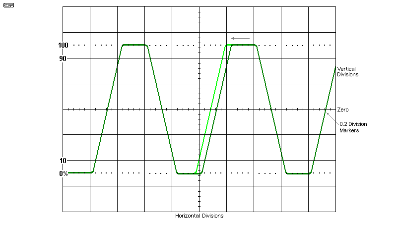
Figure 9 - Oscilloscope Graticule
The above is not from an actual scope - it's a composite image put together to show everything clearly. You will notice that the centre lines (both vertical and horizontal) have additional 'tick' marks at 0.2 division intervals. These make it easier to estimate the voltage or time being measured. There are also 0, 10, 90 and 100% indicators that are used to measure the rise or fall time of a pulse waveform. The peak values are aligned at the 0 and 100% points, and the risetime is measured between 10% and 90%. Not all scopes have these indicators. They aren't usually provided on digital scopes because they can measure the rise and fall times for you - albeit usually only by using the menus.
In the above drawing, you would adjust the horizontal position control so the 10% point on the waveform was aligned with the central vertical line (as shown in light green). The rise time can then be measured by reading the time, based on the timebase setting (e.g. 5µs/ div) and the number of horizontal divisions needed for the rising edge to go from 10% to 90%. In the case shown, it's a little over 0.8 of one division, so we can estimate around 4.2µs risetime. Not an exact science, but greater accuracy is easily obtained by increasing the timebase speed to 2µs/ div. As noted, digital scopes can measure the rise and fall times accurately, by accessing the appropriate menu(s).
The waveform completes a full cycle in 4 divisions (20µs in this example), so the frequency is 1/20µs = 50kHz. The amplitude is 5 divisions, so you can work out the voltage by referring to the vertical sensitivity. If it's 0.5V/ div, the amplitude is 2.5V peak-to-peak. Note that because the waveform is not a sinewave, you can't easily determine the RMS voltage (it's just over 2V RMS), although most digital scopes can calculate that for you. A single display tells you more about the waveform than a barrage of other test instruments.
The scope graticule is the key to taking measurements. Because most scopes don't qualify as 'high precision' instruments, and measurements are based on what you can see on the screen, expecting better than 1-2% accuracy is unwise, and some scopes don't offer that degree of accuracy anyway. However, this in no way detracts from the usefulness of the measurement. You don't use a scope for its precision, you use it because it shows you what the waveform looks like, while still providing the details of the amplitude and speed of the viewed signal. This is what an oscilloscope is for, and no other instrument can do that.
The next stages of interest are the horizontal (X) and vertical (Y) amplifiers. These generally have a fairly large voltage swing, which depends on the tube itself. The static (spot centred on the screen) voltage will normally be somewhere between 50V and 200V, and the peak to peak amplitude will typically be between ±50V and up to ±150V or more. As one plate from either axis is made more positive, the other is made more negative by the same amount. The deflection amplifiers need to have a low output impedance and be capable of high peak current, because the deflection plates represent a capacitive load. This becomes more critical with wide bandwidth scopes, because they have to deflect the beam faster.
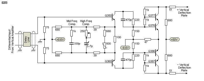
Figure 10 - Deflection Amplifier Example (Y Amplifier Shown)
The above shows a (highly) simplified Y-axis amplifier [ 3 ], and that for the X-axis will be similar, but will use higher voltages. The screen is wider than it is high, so more voltage is needed to get the extra voltage swing and deflection. The requirements are not easy to achieve. The amplifier needs high linearity, extremely good high frequency response, and must be able to drive the capacitive load of the deflection plates. HF correction circuits are shown as an example - in reality they are more complex. Both the input and output of the amplifier are balanced, although the circuit will convert an unbalanced input to a balanced output due to its design. The stage gain is about 50, and you may notice that the circuit does not use global feedback, so the transistors must be matched to get stable performance. There is a 500 ohm thermistor to correct for thermal variations.
There is one rather important part in the above, simply marked 'Delay Line'. This is used to delay the signal display for just long enough to ensure that the user can see the 'event' that triggered the sweep. Without the delay, the sweep will start but the leading edge (for example) of the pulse (or other signal) that caused the trigger could never be displayed. The delay line is typically a length of coaxial cable, coiled up and stashed within the chassis. The normal delay time is around 100ns - very short, but long enough to ensure that the edge 'event' that initiated the sweep can be observed. A delay line is only used on the vertical axis.
The timebase and trigger circuits are shown as a block diagram. In a 'real' oscilloscope, the circuitry is surprisingly complex, because the sync circuits are such a key part of how it works, and that makes it hard to figure out what is going on. The basic concept is straightforward - we only need a linear ramp, a reset circuit, and a blanking output that turns off the electron beam during the retrace period. However, the overall operation of the timebase is complicated by the sync circuits which form such an integral part of the total.
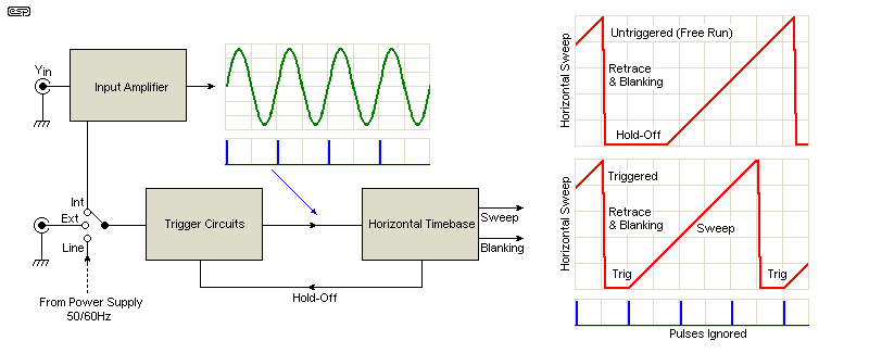
Figure 10 - Triggering & Horizontal Timebase
A basic linear voltage ramp is easy to achieve by any number of means, but a scope requires the sync input to be able to produce a stable display. There is always a 'hold-off' period in the ramp waveform, during which it can accept a sync pulse to start the sweep. If no pulse is received or it is only received during the sweep period (where it is rejected), the trace will 'free run', meaning that the display is not stable unless the input signal is at the 'right' frequency. With a free-running display, it will only be stable when the input is at an exact multiple of the timebase period. Failure to trigger is often seen as a waveform moving across the screen - in either direction.
In the above, the trigger pulse is produced at the positive-going transition. The free-running and triggered timebase waveforms are shown, and the hold-off period is essential to allow the trace to be synchronised. The sweep can only be initiated while the electron beam is at the extreme left of the screen, and it's usual for the beam to be blanked (cut off) during the retrace and hold-off periods. The beam is turned on when a sweep is initiated, and in the example shown, the screen will show 2½ cycles of the input waveform.
A faster sweep speed will show fewer cycles (or perhaps only a part of the waveform), and a slower sweep speed will show more. Trigger pulses that occur (or may occur) during a sweep are either ignored or suppressed. From the above, you can also see why the delay line is used in the vertical amplifier. It always takes a finite time for the trigger pulse to initiate the sweep, and by delaying the displayed waveform by a small amount, the start of the waveform can be seen. This is especially important when looking at pulse waveforms.
The hold-off period is important, and in many scopes it can be increased from the normal period (which depends on the manufacturer and their philosophy). A hold-off control is provided on many scopes to allow a longer period where the timebase waits for a valid trigger event, and this can improve the trace stability with difficult waveforms. Tone burst signals can be especially difficult unless external triggering is used, but adjusting the hold-off period can often make a big difference.
The repetition rate of the sweep circuits depends on the speed of the oscilloscope. A scope that has a bandwidth of 100MHz (for example) will be expected to show no more than one cycle of the waveform (per division) at the maximum frequency. That means that the sweep rate may be up to 10MHz for a 100MHz scope with 10 horizontal divisions. That is achieved with a time scale of 10ns/ division. The actual sweep waveform may be at some lower frequency, as determined by the triggering and hold-off circuits.
Yes, this is complex, and it's not easy to describe in simple terms. For many years, the triggering circuits were one of the main differentiators between the major scope manufacturers, and they are no less important today.
A simple vertical amplifier is shown next. This is not meant to represent any known scope, but it has elements taken from a couple of different circuits. The input switching allows the input to be set for AC, DC or grounded. It's important that only the input to the scope's internal circuit is grounded, or it would cause a short on the equipment being tested. The first attenuator is high impedance, and consists of a DC attenuator (using the resistors) and an AC attenuator (using the capacitors). When both are combined, the capacitive divider ensures flat response up to many MHz, which would not be the case if only resistors were used. The same approach is shown in Project 16 (Audio Millivoltmeter). The capacitors prevent unavoidable stray capacitance from reducing the frequency response. In many cases, the smaller values are either trimmer caps, or a fixed cap with a trimmer in parallel.
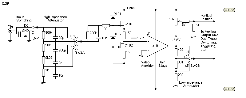
Figure 12 - Vertical Input Amplifier & Attenuators
The two attenuators shown are actually joined together on a single rotary switch, so that they follow the 1-2-5 sequence from the highest to the lowest sensitivity. The attenuator switching is usually fairly complex, because it's expected to give seamless operation over the full range. The type of gain stage depends on the scope maker, and it may be an integrated video amplifier IC as shown, or fully discrete. There may be a single gain stage, or it can be split across two or more separate stages.
The main gain stage is shown as an integrated video amplifier, as these typically have a bandwidth of up to 200MHz (50MHz with flat response is more likely), and are (or were) a simpler and cheaper alternative to a dedicated discrete design. Performance would be adequate for a low cost scope, but the major manufacturers are far more likely to use a discrete design because all parameters can be optimised. The extra cost is easily justified due to the higher price commanded by 'brand name' equipment.

| Note: Most dual-trace scopes have the provision to invert one channel, then add the channel signals (to obtain a difference trace). This can be useful to see if something changes the signal in any way, as there will only be a residual waveform is there is a difference. However, you can't increase the gain of the two channels to get greater resolution, because the scope's vertical amplifiers will clip. The resulting waveform is created by the scope, and not the external circuits. |
Noise has to be considered, but nearly all scopes show some visible noise on their most sensitive ranges. This is a surprisingly difficult exercise, because scopes have a very wide bandwidth, yet are expected to display signals of only a few millivolts. They are also required to have a high input impedance (1MΩ), and it's extremely difficult to have high gain, high impedance and low noise combined. Ultimately, the thermal noise from the input resistors will dominate at the most sensitive setting, and that can't be eliminated without breaking the laws of physics. 
As an example, the noise from a 1MΩ resistance over a 50MHz bandwidth and room temperature (25°C) is about 0.91mV (907µV), and that's with no amplification at all. See Noise In Audio Amplifiers for details on how this can be calculated for any resistance, bandwidth or temperature.
Digital storage scopes (DSOs) introduce a second parameter that's just as important as bandwidth - sampling rate. If the signal is not sampled enough times in each display cycle, there are insufficient data points to be able to recreate the waveform on the screen. Unlike audio where the sampling rate only needs to be just over double the highest frequency, a DSO needs as many samples as possible or the waveform will not be displayed properly.
Real-time sampling rates for modern digital scopes range from 500MS/s up to several GS/s - i.e. from 500 million samples per second to to several billion samples per second. In many cases, the maker will specify an effective sampling rate that's much greater than the actual (real-time) value. This can only work with repetitive signals, and by capturing several complete screen's worth of data, the waveform can be reconstructed so it's an accurate representation of the original. Glitches or other transient events may either be missed, or represented inaccurately.
The inner workings of DSOs are (for the most part) completely obscure. Even if you have a complete schematic (unlikely), it won't tell you a great deal because nearly everything is done using high speed ADCs (analogue to digital converters), ASICs (application specific ICs), FPGAs (field programmable gate arrays) and microprocessors. The analogue input circuits (channels and trigger) will use some traditional techniques to provide the 1MΩ input impedance and over-voltage protection, but they may or may not provide any gain, leaving that to the ADCs. Many of the switching functions are performed by relays, because they (like everything else) are controlled by software.
The inscrutable nature of the circuitry means that not even a block diagram is particularly helpful. As noted earlier, the software (or firmware) is designed to emulate the 'look and feel' of an analogue scope. What appear to be conventional pots (for trace positioning etc.) are often rotary encoders, and their outputs are handled by the digital electronics so that the function performed is as expected. In some cases, a single rotary control can be used for multiple purposes.
The control directly above the CH1, CH2 (etc.) buttons on the Rigol is a case in point. It's used to alter the brightness, but is also used to scroll through menu selections and adjust the cursors - the manual calls it a 'Multi Function Knob'. It's used to set the frequency of the internal high and low pass filters as well (these can be very useful, and are common in digital scopes). The Siglent scope has a similar control, which is called a 'universal knob' (this seems a bit adventurous - it is limited to the scope, not the 'universe' as such.  )
)
Most of the push-buttons are not latching types, because the microprocessor detects when a button is pressed and makes the appropriate decision (active/ inactive). The button states may be displayed on the screen, or back-illuminated with a LED. The rotary controls for input sensitivity and timebase are rotary encoders with detents, so they feel like switches. There are usually no settings shown on the front panel - they are shown on the screen instead. In some cases, the scope will 'beep' at you if you keep turning a control once the setting has reached its maximum or minimum limit. Usefully, most of the settings are retained in non-volatile memory, so when you next turn on the scope, it will be set the way you left it.
So, while you may have hoped for a block diagram here, there isn't one because there's simply no point. Even the Rigol and Siglent service manuals don't include a block diagram (let alone schematics), because the PCBs are made using SMD (surface mount device) parts almost exclusively, and the intention is that if a board fails it will be replaced, not repaired. This is common with most digital scopes (as well as many other digital devices), because repair requires access to the specific parts (which may be proprietary) and SMD rework facilities. This is beyond most hobbyists and even many (most?) professional organisations.
The facilities provided on most digital scopes are extensive. They all have the ability to save the waveform as an image (.BMP - bitmap is common) or data (CSV - comma separated values) file, and waveforms can be stored internally to generate pass/ fail tests. Most can also be connected to a PC which can control the scope via USB, they have internal digital filters so interfering signals can be removed (or enhanced), and usually have cursors that can be placed on any part of a waveform to measure instantaneous values. The list isn't quite endless, but it's extensive, and naturally varies with the brand and model of scope. The user guide or manual needs to be read thoroughly if you are to get to know the full scope of what's offered.
Although scope probes are (or appear to be) simple, they cause more problems than almost any other area of usage of an oscilloscope. In some cases you can use a simple x1 probe (straight through), but these can cause serious issues for the device under test (DUT). Even the lowest capacitance cable will add at least 100pF to the 20pF input capacitance of the scope, and because the lead is coaxial it can act as an unterminated transmission line at very high frequencies. This is why some scopes provide a 50Ω input for RF work.
The capacitive load imposed by a simple x1 probe can cause some circuits to oscillate, stop RF oscillators from working, or otherwise cause circuit malfunctions or general misbehaviour. Not the least of these is severely reduced frequency response in high impedance circuits, caused by the cable capacitance. In short, it's uncommon that you can use x1 probes for a great deal of standard measurements, where the frequency is greater than a few kHz and/ or impedance is more than 10kΩ or so.
For this reason, the x10 probe is one of the most common and popular oscilloscope accessories. In many cases they are indispensable. The drawing below shows the essential parts.
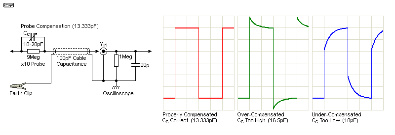
Figure 13 - x10 Attenuator Probe Details
It's all deceptively simple, but all x10 probes include a miniature trimmer capacitor that's intended to be adjusted by the user to ensure correct high frequency operation. All scopes have a 'Probe Adjust' signal available on the front panel. The output is a fast risetime squarewave, usually between 1kHz and 2kHz, and providing around 1-2V peak-to-peak. The x10 probe is connected to the terminals (signal and ground), and the trimmer cap carefully adjusted until the leading edge of the waveform is displayed correctly (as shown in red).
Failure to adjust the probe at regular intervals will result in a display that is inaccurate at high frequencies and/ or impedances. There are also x100 probes, some of which are intended for higher voltages than standard or x10 probes. The limiting factors are the dielectric strength of the trimmer cap and the voltage withstand of the 9Meg (or 99Meg for a x100 probe) resistor.
There are some x10 probes that have the compensation cap in a 'pod' at the oscilloscope end of the lead. These are much less common, but they may have an advantage for probes designed for higher than normal voltages. A cap is still used across the 9Meg resistor, but being a fixed value it's smaller than a trimmer and can use a high voltage dielectric. The process of compensation is the same, but the cap across the probe's resistor must be a little larger than normal. That means that the probe itself is always over-compensated, and the response is pulled back into line by adding more capacitance at the scope end of the cable.
The topic of probes is the subject of complete articles, some of which can be found on line. There is also some disagreement about the terms 'under-compensated' and over-compensated', with some material using the terms in the opposite way to that shown above. The terms don't matter, provided you understand the concept and compensate your probe(s) properly. It's also worth pointing out that the act of compensation ensure that the frequency response is linear up to the limits of your scope. Although it's done with a relatively low frequency squarewave, the response extends to many MHz. When the squarewave is reproduced perfectly, your probe will be flat to 100MHz or more.
While it is not immediately apparent, the circuit shown above has a turnover frequency of around 1-2kHz. Beyond 10kHz, the effect is that all higher frequencies are either boosted or attenuated by around 2-2.5dB. This is probably counter-intuitive, but if you examine the capacitive divider created by Cc (compensation cap) and the combined capacitance of the scope and cable, you get a simple voltage divider that is frequency independent. Compensation simply ensures that the resistive and capacitive voltage dividers are perfectly matched. This is why all oscilloscopes use a probe adjustment frequency of 1-2kHz.
Standard x10 probes (by far the most useful for general work) range from around $20 for basic (and marginal quality) types that you'll find on ebay and the like, up to $10,000 or more for high speed name brand types (and no, that is not a misprint). When you buy a scope, it will usually come with probes and the cost of them has to be considered when you are comparing different products. Few of us need (or can afford) to spend $10k for a single probe, but it's unwise to imagine that you'll get high quality and durability if you only pay $20. The middle ground ($30-$75) should get you something reasonable, but you must verify that you aren't simply paying 3 times the price for a cheap Chinese version that you can get elsewhere for $20.
There is a wide range of specialised probes available, but some come with very scary price tags. Current probes are a case in point, with the cheapest being around $250, and ranging up to $5,000 and more. If you need to monitor current at mains frequencies (which is very useful), then it is far cheaper to build a current monitor such as those shown in Project 139 or Project 139a. Similar techniques can be used for higher frequencies, but it's generally not as convenient as a dedicated current probe. As always, you have to balance the need against the cost.
Another useful (but expensive) probe type is a differential probe. These are isolated, and don't need the standard ground clip. Some are designed for very high voltage use (allowing isolation to mains voltage standards). This is a case where the need really must exist, because the cheapest is around $380 and most are a great deal more (over $6k is not unusual). The cost is dependent on the speed, isolation voltage and accuracy, and this is not something that you buy on price, because your life may depend on it. Most differential probes are battery operated because they are active (using ICs, transistors, optocouplers, etc.). Nearly all other probes are passive, and do not require power.
In some respects, this topic is now a moot point. A quick search will reveal that almost no-one makes new analogue scopes, so the main way you'll get one is to buy it second hand. There is a small number of new models available (at the time of writing), but most are more expensive than much faster digital models, so it's hard to justify the extra expense. The days of cheap, basic analogue scopes are well past, and second hand is always a risk - especially if you aren't able to make repairs as needed. The chances of getting a replacement CRT are probably close to zero, other than for very expensive 'name brand' models.
Despite the many advantages of digital instruments, they have one major trap for the unwary - sampling. If you have a scope set for the wrong timebase (sweep speed), an analogue CRO will just show a mess, but a digital scope can show a waveform that looks as it it may be what you expect. The only trouble is that if the signal frequency is greater than half the sampling rate (the Nyquist frequency), you get a phenomenon called aliasing, and the waveform you see is not the real thing - it's been created because the timebase setting is wrong.
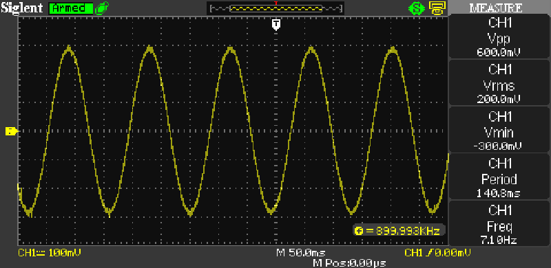
Figure 14 - 900kHz Waveform Showing Aliasing
The above used a 900kHz input, but with the timebase set for 50ms/ division. The display should be a solid block of colour, but it's not - it shows a sinewave. One frequency readout says 899.999Hz (which is correct), but the measurement panel claims the frequency is 7.10Hz (which is quite obviously incorrect). This is a clear display of the problem, but it isn't something that you would normally do by accident unless you deliberately set up the scope incorrectly (as I did for the waveform shown). However, if you are taking measurements of RF circuits that incorporate lower frequencies (such as audio), you can easily be tricked unless you are careful.
An analogue scope does not have this problem - it will generally show either a jumbled waveform that can't be synchronised, or a fairly solid 'block' of signal with no discernable detail. What you see depends greatly on the waveform itself. Analogue scopes also show a variable intensity depending on the speed of the electron beam which creates a moving spot on the screen. If the spot is moving very quickly, its intensity is reduced because it doesn't have enough time to excite the phosphors on the screen itself. For example, a very fast squarewave will often show horizontal dashed lines, separated by the amplitude, but with an almost invisible rise and fall time.
Should the timebase be too fast, you may see an almost horizontal line which is just the part of the waveform that can be displayed. With an analogue scope it will probably be very faint, but most digital scopes do not have variable intensity, so show everything that can be displayed at the same intensity. This is not always desirable, but at the time of writing, variable intensity digital scopes are much more expensive than their fixed intensity brethren. These are often referred to as DPOs (digital phosphor oscilloscopes), as opposed to DSO (digital sampling oscilloscope) [ 5 ]. You will also see references to 'mixed signal' oscilloscopes, which usually combine 2 full function scope channels and 16 digital (logic analyser) channels.
As a general rule, analogue scopes are easier to use and faster to set up for a waveform than digital types. Part of this is due to the fact that there is no aliasing, but they have a simpler control-set, with fewer options. Many service techs prefer analogue because they can have a visible trace with only a few adjustments, and the trace is unambiguous. This is especially true when you consider all of the menu driven options on digital scopes. Most require the menu system to change from AC to DC coupling, or even to change the trigger polarity. These are all front panel controls on analogue scopes because they don't normally have a menu - all controls are instantly available.
While the options are limited, for general work they provide everything needed for most servicing tasks, and the 'bells and whistles' of digital scopes are not usually needed. There are exceptions of course, but they are (perhaps surprisingly) few and far between. Many of the 'old school' service techs are so used to using their analogue scopes that they find digital versions somewhat tedious or even annoying for many standard tasks.
One of the most useful things about a digital scope is the ability to capture a single event, then stop. This allows waveforms or transients to be captured (for example), and examined in detail at your leisure, or posted as images in a web page as done here. While analogue storage scopes were not uncommon, they were very expensive, and the storage didn't last forever. The storage function was done within the CRT itself, and allowed the trace to be maintained (stored) for several minutes. Polaroid cameras were often added (with customised hoods to attach to the scope itself) for permanent storage. A digital scope can retain the waveform for as long as you like - many even allow the trace to be saved in internal non-volatile memory so it can be kept forever (or for as long as you have the scope.  )
)
One other function of digital scopes also deserves a mention - averaging. This allows you to take a reading of a noisy signal, and by means of the averaging function, the noise (which is random) will disappear or be greatly reduced. This makes it possible to measure a waveform that may otherwise be buried in noise. You almost always need to use external triggering to be able to obtain a stable display when the averaging function is used.
It is hoped that this article has helped shed a little light on the workings and use of oscilloscopes. Despite the misgivings of many hobbyists, a scope is (IMO) an indispensable piece of test gear. There is nothing else that can tell you as much about how a circuit is functioning, or what it's doing wrong. A scope certainly doesn't take away the need for more traditional test gear, and you still need your multimeters, signal generator and other tools. Modern digital scopes can eliminate the need for a frequency counter unless extreme precision is required, and the ability to provide true RMS AC voltage measurements is also very handy.
Whether you get a stand alone instrument or a USB scope that's driven from a PC depends on your needs and budget. There are a few things that USB scopes do very well, but they are usually harder to 'drive' than a conventional instrument. Since decent versions (having at least 50MHz bandwidth) are usually just as (or more) expensive than a stand-alone scope, it may be hard to justify the extra cost unless you need the PC's processing power for analysis.
Before you commit to any of the available offerings, it's a good idea to do a search for the brand(s) and model(s) you are considering. People the world over have contributed reviews and forum posts that may alert you to any issues that various scopes may have. Be careful though, because not all reviews are by people who know what they are talking about.
Regardless of the scope you have (or intend to get), don't forget the probes. I often use simple coax and alligator clips when working with low frequency/ low impedance circuits, but you really need to have a set of x10 probes. Some are available with a x1/ x10 switch, but in general a fixed x10 probe is a better option. Forgetting to set the switch or make note of whether it's set for x1 or x10 can really confuse your measurements, and the x1 setting can annoy some circuits which misbehave due to the capacitive loading. Digital scopes let you specify that you are using a x10 probe, so all measurements are scaled to the correct voltage range.
Don't expect that you can buy a scope and instantly make sense of it and what it does. It takes time to acquaint yourself with the controls and to understand the waveforms you are looking at. Never imagine that it's not necessary to read the manual (even if you have used scopes all your life), because there are functions available now that were unheard of only a few years ago. You have to be prepared to look at different waveforms and work out what you can do with them using the scope's inbuilt maths (aka 'math') functions - these provide capabilities that can be extremely useful, even for fairly basic measurements.
I got my first oscilloscope (or CRO as we knew them at the time) when I first started to become serious about electronics at around 17 or 18 years old. I have had one ever since, and have literally never been more than 5 minutes away from one if I needed it. Most of the projects shown in the ESP site would have been much harder to perfect without a scope, and some would simply have not been possible at all. In all cases, the use of an oscilloscope gives you information that you cannot get any other way.
 Main Index
 Articles Index