
|
| Elliott Sound Products | Amplifier Basics - How Amps Work (Part 1) |
 Main Index Main Index
 Articles Index Articles Index
|
In the beginning the vacuum tube was the only way to amplify, and valves (or 'tubes') survive to this day, with a dedicated following of 'believers' who are convinced that the development of the transistor (or indeed, any semiconductor) was fundamentally a bad idea. This is not a discussion I intend to follow - I intend simply to state how these devices amplify a signal, and the factors that determine voltage and current gain. For more information about valve circuits, look at the material shown in the ESP Valve Pages.
The basic amplifying valve (there are many different types with higher complexity) has three elements. These are ...
When a positive voltage is applied to the anode with respect to the cathode, an electron stream is emitted from the cathode and flows to the anode, completing the circuit. The grid is a fine coil of wire, suspended between the other two elements. A negative voltage on the grid (with respect to the cathode) will repel some of the electron stream, causing the current to be reduced. If the voltage on the grid were to be varied, then the cathode to anode current must also vary, and an amplifier is born. Figure 1.1 shows the basic circuit of a valve voltage amplifier.

This circuit configuration is known as 'common cathode', because the cathode reference point (earth) is common to both input and output. By placing a resistor 'Rk' in the cathode circuit, a voltage is developed because of the current flow. If the grid is referenced to earth (ground), then the grid is negative with respect to the cathode. The voltages shown on the circuit are typical of a single element of a 12AX7 twin triode. Note that the two valve pins that are not connected are for the heater. This is used to heat the cathode so that it emits electrons more readily.
The cathode resistor will cause the circuit to reach a stable current, where any attempt at increasing the cathode current will cause a greater voltage across the resistor, making the grid effectively more negative and reducing the current. A point of equilibrium is quickly reached, where the circuit operates in a stable manner. This is known as cathode biasing, and is most common with signal level and low power amps.
By applying a varying voltage (the signal) to the grid, the current between cathode and anode will vary too. Since the anode load is a resistance, a varying voltage will be developed which will (hopefully) be greater than the voltage applied to the grid. The input voltage has been amplified.
Because the signal voltage on the grid is 'fighting' the attempt of the cathode resistor to maintain the current through the valve at a constant value, this is a form of feedback. It is also known as cathode degeneration. The name is of no consequence, because as local feedback, it will improve the linearity of the stage but reduce the gain. In reality, the improvement in linearity is only minor, and leaving out the capacitor can increase noise in sensitive circuits - especially hum that is induced into the cathode from the heater, which was nearly always operated from AC in the past, but DC heater supplies are now common.
Where the cathode is directly heated (the filament has the oxide coatings directly applied), DC operation is mandatory or hum would result. Directly heated cathodes will always emit electrons unevenly, because of the voltage gradient across the filament. The only common directly heated valves used in any number these days are rectifiers.
Note that for indirectly heated cathodes, the heating element is called the heater, but for directly heated cathodes it is more commonly referred to as the filament (as in the heated filament of a light bulb).
Because valves have a relatively low voltage gain, it is common to bypass the cathode resistor with a capacitor to defeat the local feedback and extract as much gain as possible, as is shown in Figure 1.1. The gain (or more correctly, the transfer characteristic) of a valve is sometimes measured in mA/V - which tells us how many milliamps change in anode current will occur with a grid voltage change of 1 Volt. Another common way to describe this is 'mu' (µ) or amplification factor. Yet another value is common with valves - the 'conductance' (aka mutual conductance or transconductance), which is the opposite of resistance, and is expressed in Mhos (Ohms backwards - seriously!) or Siemens.
One problem with valves has always been the number of different methods used to describe what is essentially the same thing. Depending entirely which book you happen to be reading, you will see the effective gain quoted as mA/V, mutual conductance ('gm', in Mhos or more commonly µMhos), or the equally obscure term 'Amplification Factor', none of which has any direct relevance to the gain you can expect without further calculation.
The output impedance of the circuit of Figure 1.1 is about 44k - it's the value of the plate resistor in parallel with the internal plate resistance. Rg2 is the grid resistor for the following stage, and at 1M, loads the output and reduces gain.
There are four main characteristics that are quoted for any given valve. These are:
One important thing to realise about valves is that everything changes. The characteristics vary widely with plate voltage, load resistance, bias current and just about everything else you can think of. Despite this, it is still possible to design a circuit using valves that will be repeatable from one unit to the next, provided the designer knows what s/he is doing.
A typical signal valve (such as the 12AX7 high mu dual triode) has a plate resistance of 80k, an amplification factor (mu) of 100, and a gm (using the circuit of Figure 1.1) of about 1250µMhos, which can (by simple mathematics) be converted into a figure of 1.25mA/V, meaning that a change of 1V on the grid will cause a change of 1.6mA in the anode current. This does not actually mean what it says, since the valve might be quite incapable of sustaining an anode current of 1.25mA under all circumstances. However, a change of 0.1V at the grid can cause a change in plate current of 0.125mA - the measurement is typically 'normalised' to make comparison easier.
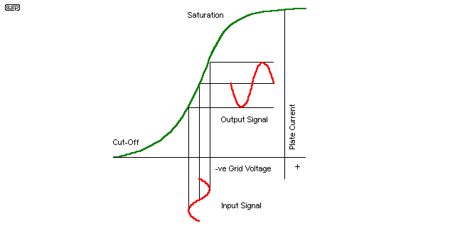
Let us now have a look at how the valve amplifies the signal. The transfer curve in Figure 1.2 shows the input waveform applied to the grid, at any convenient frequency. As the signal becomes more positive, the valve draws more current, until at the peak of the waveform, the grid voltage has been made 0.1V more positive than it was before. Therefore, the anode current is 0.125mA greater that it was before. Using Ohm's Law, 0.125mA with a resistance of 100k means that the anode voltage should be 12.5 Volts lower than when in the idle (or quiescent) state.
This would seem to imply that the valve has a gain of (12.5 / 0.1) 125 - not a chance! The circuit of Figure 1 will have a typical voltage gain (Av) of much less than this. Why? Because the valve's internal plate resistance wasn't considered. This is effectively in parallel with the plate load resistor and external load (the grid resistor of the next stage). When these are taken into consideration, the gain can be calculated at around 55 - somewhat shy of the figure obtained before considering the complete circuit.
The only way to be certain what a valve will actually do is consult the manufacturer's data, and refer to the transfer curves for the mode of operation and cathode current you wish to use. Valve characteristics, supply voltage, plate current, plate voltage and the impedance of the next stage all have a profound effect on the performance of any valve.

As can be seen from Figure 1.2, the transfer curve is not linear, which means that as the valve approaches cut-off (turned off completely) or saturation (turned on completely) the characteristics change, and distortion is introduced. A (very) rough estimation of maximum RMS output voltage to keep distortion below 1% is about 0.1 of the quiescent plate voltage, but often less. Thus, with a plate voltage of 125V at idle, the maximum output voltage will be 12.5V RMS. This assumes that the valve has been biased correctly in the first place. From the graph we can see that at high values of negative grid voltage the valve will cut off, while at low (or positive) grid voltage, the valve is turned on as hard as it can.
A valve can be thought of as having an infinite input impedance (although this is never realised in practice). The input impedance is approximately equal to the value of the grid resistor for audio frequencies. The output current is therefore controlled by a voltage at the grid, so the valve might be considered a voltage controlled current source (or VCCS).
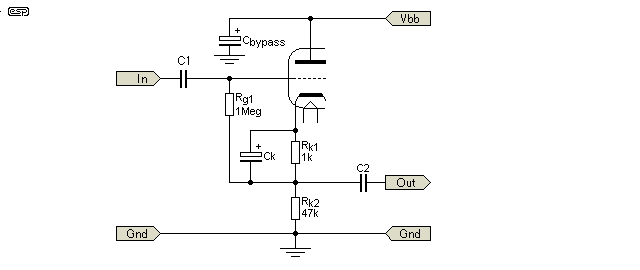
Figure 1.3 shows a valve current amplifier, commonly known as a cathode follower, or common plate (because the plate circuit is common to both input and output - for AC signals only). Although this circuit can provide a useful increase of current, and an equally useful decrease in output impedance, it has a voltage gain that is less than unity. Typically, this will be about 0.8 to 0.9, so for every volt of signal applied to the input, we only get about 850mV output.

The cathode follower is typically used where a low impedance output is desired, since the output impedance of most valve circuits is rather high (equal to the value of the plate load resistor in parallel with the internal plate resistance). Simply attaching a low impedance load to a voltage amplifier stage will cause the output level to be dramatically reduced, so the current amplifier (cathode follower) is a useful stage. The output impedance of the circuit of Figure 1.3 can be expected to be about 1/10th the value of the cathode resistance Rk2 - but this is highly dependent on the valve itself and its operating current. The available current is very low, so the circuit will not be able to drive a load much less than Rk2, or 47k. Remember that output impedance and drive capability are not related.
Note that the grid must still be biased to an appropriate voltage negative with respect to the cathode. The bypassed cathode resistor is used as before, but the grid is connected to the bottom of this resistor, and not ground. If it were connected to ground, the circuit would be capable of only very small signal levels before it distorted.
Finally, we can combine a voltage amplifier stage and a current amplifier stage, and get a power amplifier. Cathode followers are unusual in valve power amplifiers, and it is far more common to use a plate-loaded 'push-pull' output stage, using a transformer in the plate circuit to match the high voltage and relatively high impedance of the output valves to the impedance of the speaker. In a few cases, output stages have been configured to use part of the transformer winding in the anode circuit, and some in the cathode circuit. This can improve linearity, but makes the output valves harder to drive.
'Transformerless' valve output stages had a short period of popularity, but most required high impedance loudspeakers which were expensive and disappeared only a few years after they were introduced. The high voltage requirement and comparatively low current capabilities make valves unsuited to direct-coupling to 'normal' speaker impedances.

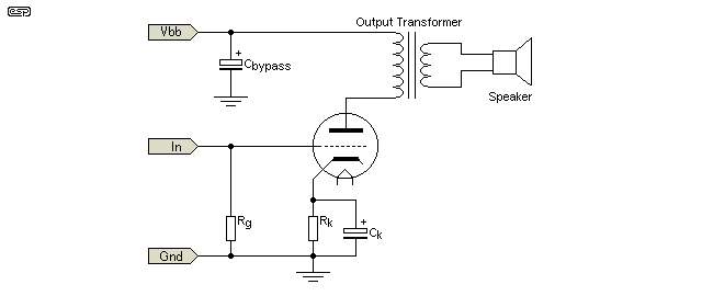
Figure 1.4 shows a very basic valve power amplifier, using a triode in 'single-ended' mode. The output transformer converts the high voltage, high impedance plate circuit of the valve to a low voltage, low impedance signal for the loudspeaker. Because the primary of the output transformer must carry the full DC quiescent current of the valve (which will be a large, high current unit), it needs a very large core of laminated steel with an air gap to minimise saturation effects and distortion.
Interestingly, these inefficient and high distortion amplifiers have made a comeback in recent years. However in the heyday of the valve, the inefficiency and high distortion of these circuits was such that they were replaced in nearly all installations by more efficient and lower distortion circuits, such as that shown in Figure 1.5.

The valves shown for the output are called pentodes (from penta - five), having 5 electrodes instead of the three for a triode. The second grid (called the screen grid, or just screen) increases the gain of the valve dramatically, while the third grid, the suppressor, prevents what is called 'secondary emission' from the plate. The screen accelerates the electron flow so much that electrons bounce off the plate, or dislodge others. The addition of the screen gives the valve some nice characteristics, such as much higher gain, but also some nasty ones (lower linearity, more distortion), which the suppressor counteracts to some degree. The suppressor grid is almost always connected internally to the cathode. It is not uncommon for designers to connect pentodes as triodes, by connecting the screen and plate together.
The first stage of the circuit is interesting, and is called a phase splitter. It is a combination of a voltage amplifier and a current amplifier, having equal values of resistance in each circuit (i.e. Rp = Rk2). Because all valves have the same 'polarity', they cannot be used like transistors or MOSFETs, but must be driven with their own signal of the correct polarity.
The incoming signal is therefore sent 'as is' to one valve (from the cathode circuit), and is inverted for the other - hence the term push-pull. As one valve 'pulls' the anode current lower, the other simultaneously 'pushes' it higher. In a properly designed circuit, the two output valves will pass the signal between them with little disturbance. Any disturbance in this region is called crossover distortion, because it happens as the signal crosses over from one valve to the other.
Notice something else quite different. The cathodes of the output valves are connected directly to earth, and the grids are supplied with a negative bias from a separate negative power supply. This is the most common method of biasing output valves in high power circuits, having a much greater efficiency than cathode biasing.
For many large output valves, it is not even considered a good idea to use cathode biasing, because the amount of negative grid voltage required is too high. Voltages of up to -60V are not uncommon with high power pentodes or another common type, beam power tetrodes (I will not cover these in more detail, but there is much information to be found on the web). Using cathode bias for this sort of voltage and current is inefficient and reduces the output power dramatically.
The above is but a very small offering from the world of the vacuum tube. As I said in the introduction, this is not designed to be a complete electronics training course. The circuits presented are basic only, which is to say that they will all work, but are not optimised in any way.
For further reading, the most highly recommended work is the rather old (but still considered the reference manual) "Radiotron Designer's Handbook", by F. Langford-Smith and originally published by Amalgamated Wireless Valve Co. Pty. Ltd. in Australia. My copy is dated 1957, but it has recently been republished (although I think it is quite expensive, unfortunately).
Overall, the valve is still an almost mystical thing, but in all honesty, modern amplifiers using transistors or MOSFETs are so vastly superior in terms of fidelity, efficiency and reliability, that I really don't see what all the fuss is about. Having said this, I was using a valve preamplifier on my own system until recently.
There is no doubt that valves do have some very nice characteristics, and for guitar amplifiers there are few guitarists who would argue otherwise. A 'soft' overload behaviour means that a valve amp does not sound as harsh as a transistor amp when it is overdriven - which is great for guitar, but a hi-fi should never be overdriven anyway, so the point is moot.
The problems that befall valves are many, and include ...
On the positive side, valve amplifiers have a 'warm' sound, partly because of the low order harmonic distortion introduced. A good valve amp will also have a very wide bandwidth, and will have an easy job driving loads that might cause some solid-state equipment to have severe heartburn (or just blow up on the spot).
At low levels, valve equipment has vanishingly small distortion levels, and when all is said and done, there is something nice about little glass tubes, with little lights inside, making your music. For more on the topic of valves, see the Valve Index.
Overall though, valves are an expensive, fragile and unreliable way to amplify anything these days. Well designed, modern 'solid state' equipment will easily surpass the best valve gear from any era, and even rather pedestrian circuits can easily beat the best valve designs for noise and distortion.
Previous (Intro) Next (Part 2 - Bipolar Transistors)
 Main Index Main Index
 Articles Index Articles Index
|