
|
| Elliott Sound Products | VI Limiters in Amplifiers |
 Main Index
 Articles Index
This is another of Phil Allison's contributions, and discusses specific experience that Phil has had with short circuit protection circuits in power amplifiers. These are commonly called VI Limiters, since they limit current (I) based on the voltage (V) across the power transistors.
As Phil will explain, not all manufacturers get these circuits right, and the sonic artifacts can be extremely unpleasant. In extreme cases, the very circuit designed (?) to protect the output stage
can do exactly the opposite, and cause the amplifier to fail, and / or damage tweeters into the bargain. Have I ever mentioned in these pages that I don't like protection circuits? Hmmm, I thought so 
Most IC power amps use some form of protection, with the National Semiconductor (now part of Texas Instruments) LM3876/ 3886 being very common for high-quality audio. However, they use SPiKe™ protection system. The acronym stands for 'Self Peak instantaneous Temperature' (temperature is 'Ke' for Kelvin). This protection is most unpleasant when invoked, and is described (with a waveform capture) in the article IC Power Amplifiers - How To Get More Power, as well as in Project 19 (Single Chip 50 Watt / 8Ω Power Amplifier). If the voltage is kept low enough (typically no more than ±30V), the protection circuits won't be invoked unless there's a fault.
Virtually any power amplifier would be quickly destroyed by a short on the output if there were no internal limit on the output current. This is because the power supply can deliver a short term power level much greater than the capacity of the transistors used in the output stage. The answer is some form of output current limiting to prevent damage under short circuit or near short condition on the speaker terminals. Many schemes have been used to protect the output devices in an amplifier, from fuses and current trips in the power supply to elaborate electronic circuits.
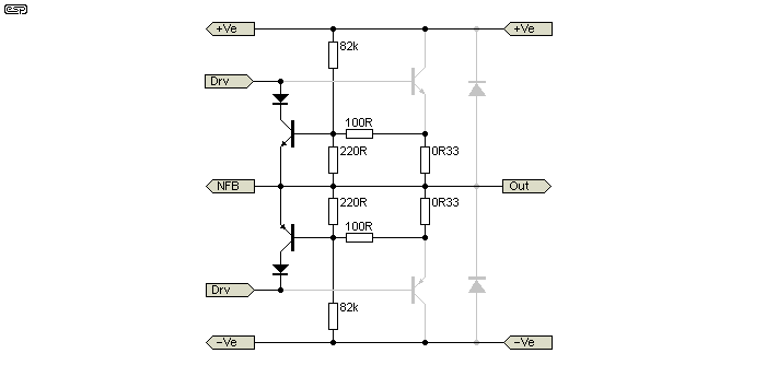
The most common technique used is known as 'VI limiting'. A pair of NPN and PNP transistors is connected across the drive signal to the output devices and fed from a resistor network that senses both the voltage across and the current through them. When the combination of V and I, which is the power dissipation, is more than what can be handled safely then the protection transistors conduct the drive signal away just enough to prevent output transistor failure (see Figure 1).

Figure 1 - Basic VI Limiter Circuit
The output transistors are shown in representative form, coloured grey, and may be Darlington, compound pairs, or any combination thereof. The remainder of the amplifier is not shown, since this is largely irrelevant to the operation of the protection circuit. The diodes shown in grey are nearly always included (see Editorial Comment).
You may wonder why amplifiers need to deliver any current into a short circuit, after all surely this is a fault situation. True enough, provided all the amplifier ever had to do was drive pure resistors. The problem becomes more obvious when you consider that amplifiers have to drive loudspeakers. Real loudspeakers are a 'reactive load', that is their impedance changes with frequency.
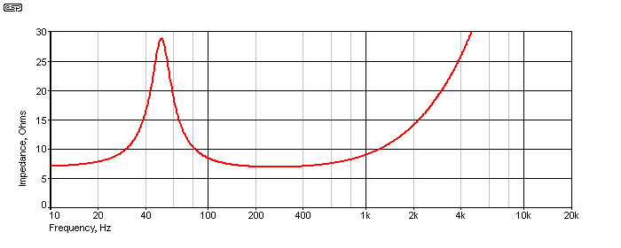
For example, a nominal 8Ω 12" (300mm) driver in a sealed enclosure will have a bass resonance at some low frequency and around that same frequency an impedance peak of 20Ω or more. At frequencies above 1 to 2 kHz the impedance rises doubling each octave due to the inductance of the voice coil. Systems having tuned ports result in double impedance peaks in the low frequency range only dropping to the 'nominal' value at two points, in the middle of the peaks and at 250 Hz where the figure is often measured. An impedance that rises with increasing frequency is inductive and the opposite capacitive.
While a loudspeaker's low frequency impedance peaks are caused mechanically, by the back EMF generated by the moving voice coil, they look to the amplifier exactly as if tuned circuits had been connected. An equivalent electrical circuit can be derived and contains large inductances in parallel with large capacitances. This is in addition to any passive crossover network that may be installed. The amplifier is required to drive this complex load at any frequency and level without distortion. Figure 2 shows the equivalent circuit of a single driver in a sealed enclosure.

Figure 2 - Equivalent Circuit Of A Typical Loudspeaker Driver
Figure 3 shows the impedance versus frequency for the simulated speaker, and as can be seen, it looks very similar to the impedance response curve you see with many real loudspeakers. This (of course) is the whole point of the exercise.

Figure 3 - Impedance Curve Of Simulated Loudspeaker
This can be built using the component values specified in Figure 2, or you may want to experiment further. Attempting to make the simulation 'look' like a real loudspeaker system, including crossover networks and additional drivers is possible, but becomes quite complex. Since all speakers are different, this approach is neither suggested nor recommended, due to the cost of trying to re-create simulated versions of even a small number of systems.
Out of Phase Current
A load impedance that is inductive or capacitive (i.e. reactive) has one important characteristic, the current and voltage are 'out of phase'. Having a current and voltage phase shift means zero volts and zero amps no longer coincide. The amplifier has to produce high current when its output voltage is zero. Also, it will have to produce negative current when the output voltage is positive.
An amplifier which limits heavily into a short circuit can do neither of these things. The amount of out of phase current a good amplifier should be able to deliver is a moot point. Amplifier makers want speaker makers to tame their designs to make life easier for them. Speaker makers reject any restrictions and often produce systems that only the best amplifiers can drive without VI limiting. The market has to sort out which combinations don't work together. This is not a happy situation but it is reality. Amplifier makers take for granted a few facts about speakers. Systems are mostly nominal 8 or 4Ω and their impedance does not go much below this value as it is close to the DC resistance of the driver(s) involved.
The assumption based on experience and used by many amplifier designers is that the phase angle will at worst be no more than 45° and then be at an impedance that is about 40% higher than the nominal value. For most loudspeaker systems this assumption would be true. The above situation can be simulated by a load impedance formed by a power resistor of 4 or 8Ω in series with an air cored inductor of about 5 to 10mH (milli Henrys). At the frequency where the phase angle is 45° the load will be either 5.6Ω or 11.2Ω (see note 2). Any good amplifier should be able to drive this combination at full level and any frequency without problems. However, even some well known ones don't.
What's the Problem?
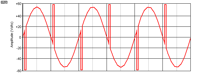
If the VI limiting circuit prevents current from reaching the value needed to drive a load at a particular frequency then an unexpected thing happens. The stored energy takes over from the amplifier and dumps a large spike of voltage and current back into the output stage, twice each cycle. Each spike is equal to or more than the amplifier supply voltage and starts around the zero crossing of the wave form lasting about half a millisecond (Figure 4). Such spikes of possibly over 100 volts sound very nasty. They usually don't damage the bass driver but other speaker components (like piezo horns) and even an amplifier has been known to quickly fail because of them.

Figure 4 - Voltage Spikes Caused By VI Limiter
Why don't amplifier makers get it right?
Mostly they do. The release in the late 1970s of Hitachi's Power MOSFETs eliminated the need for VI limiting allowing most MOSFET amplifiers to have only a simple peak current limit set by zener diodes across the MOSFET gate drive and rely on supply rail fuses to open when the amp was shorted. These amps can drive any known loudspeaker (See note 1). Amplifiers using bi-polar output transistors, even the likes of Motorola's best, are at higher risk of failure and fuses don't blow fast enough. Cost restrictions set a limit to how many output devices can be used, and sometimes the need to prevent output stage overheating and device failures when shorted produces a design which is unable to drive nominal 4Ω loudspeakers. Another reason for not getting it right is that there is no industry standard for reactive load testing. Resistive load tests are all that are normally done or specified. Similarly speaker makers don't fully specify their products either.
How much out of phase current do amplifiers need?
It depends on the loudspeaker, but the more the better. A first class amplifier is one that can deliver the same current at zero volts as it does at maximum output reducing only when the output swings to the opposite polarity. Such an amplifier rated at 800 watts into 4Ω would have a short circuit current of at least ±20 amps. A lower current capability is often considered acceptable as it will satisfy the majority of loudspeakers, a level of 50% of the maximum output current available at zero volts reducing to zero at full opposite supply. This takes into account the 40% higher impedance expected at the frequency of a 45 degree phase angle and the fact that current is 71% of maximum at zero volts.
Testing the Amplifier
To find what a particular amplifier can deliver in the way of out of phase current requires a couple of bench tests. Neither is complicated or out of the reach of the average technician. Only a few low cost items are needed - a high power air cored 5mH inductor (see Note 3) and a 0.1Ω 10 watt resistor as well as the usual 4 and 8Ω dummy load resistors.
Test 1
Connect the 5mH inductor in series with the dummy load and the amplifier with the oscilloscope connected across the amplifier output as usual. Set the sine wave generator at about 250 Hz and using the 8Ω load gradually increase the level until either spikes are seen or clipping occurs. If there is no problem switch the load to 4Ω and the generator to 127Hz and repeat the above. The generator can be swept from 50Hz to 500Hz to investigate further for any spiking though if there is no problem at either of the test frequencies then there will usually be no problem at any other. Note the power level at which any spiking occurs.
Test 2
Connect the 0.1Ω resistor to the amplifier and the oscilloscope leads directly to the resistor. Set the generator to 250 Hz and switch to square wave. Couple the signal into the amplifier input through a capacitor of about 2.2nF. This creates a series of spikes of low average power that does not stress the amplifier. Increase the input level until clipping of the spikes is visible and note the oscilloscope reading in each polarity. Multiply by 10 to get the answer in amps. This test reveals the current available at zero volts and should be compared with the rated output current into 4 or 8Ω derived from the power output specification. If the positive and negative current readings are asymmetrical or very high there may be a fault with the VI limiting circuit itself or the amplifier is NOT short circuit proof.
A load using a resistor equal to the rated impedance and an inductor in series driven at 45° phase angle allows a simple pass or fail test for an amplifier depending on whether any spikes on the sinewave are heard or seen on a oscilloscope screen. The amount of current available into a short circuit is also a useful guide. It should be 50% of the peak current output into the rated load. Amplifiers that fail these tests may be put on 'restricted duties' and used only with 8Ω nominal loads or speakers that are known as easy to drive. Modification of the VI circuit is always possible but you have to know exactly what you are doing as the output stage may be rendered vulnerable.
Most amplifier circuits with VI limiting show diodes connected between the output and the +ve and -ve power rails - these are shown in grey in Figure 1. The purpose of these should now be obvious - they will 'catch' the spikes generated under the conditions Phil has explained. These will (hopefully) prevent the destruction of output transistors by shunting the excess voltage and current back into the power supply which simply absorbs the energy. The diodes prevent the amplifier's output voltage from ever exceeding the supply by more than 0.65 volt or so, and therefore prevent reverse biasing of the transistors under fault conditions.
Needless to say, this provides zero sonic benefit, since the spikes will still occur, but they will now be limited to a little over the amplifier's supply voltage. The amp will probably not self destruct, but it will sound just as horrible when driven beyond its current limits. VI limiter circuits should always be designed to ensure that they never operate under normal conditions. This is often a great deal harder than it sounds, and requires extensive testing.
Some years ago, high power amplifiers (i.e. anything over about 400W) nearly always used MOSFETs rather than bipolar transistors, and this was especially true of professional units for sound reinforcement. There were very good reasons for this, as Phil has explained. Most newer amps use bipolar transistors, as they are cheaper, and modern BJTs are very rugged, and have very good gain linearity vs. output current.
The ability to drive virtually any load without the need for VI limiter protection is one of the all time great advantages of lateral MOSFETs. Naturally, the requirement that there are sufficient output devices to handle the load still exists, but lateral MOSFETs are far more tolerant of fault conditions than bipolar transistors, and are not subject to a most undesirable problem known as 'second breakdown'. The same cannot be said for 'vertical' MOSFETs (i.e. switching types, intended for switchmode power supplies, Class-D amplifiers, etc. These are generally unsuitable for linear operation.
Second breakdown occurs in bipolar transistors when a small section of the silicon die becomes hotter than the rest due to an overload condition, or where the devices are too small for the job. This increases the gain in that small section, and it therefore does even more of the work, causing it to get hotter still. Thus a repeating cycle is started, which results in device destruction. This happens very fast (in as little as a few tens of milliseconds), and it is virtually impossible to protect the device once second breakdown has started. The VI limiters are designed to prevent the device(s) from ever exceeding the manufacturer limits where second breakdown is known to occur.
As Phil has shown, some attempts at achieving that goal are somewhat less than a complete success.
 Main Index
 Articles Index