
|
|
| Elliott Sound Products | Project 265 |
 Main Index
Projects Index |
| Introduction | Description | Optional Meter | Optional Filter | Bridge Driver | Power Supply | Conclusions | References |
The logarithmic amplifier described can be used with any signal source that requires you to locate a null. It can also be used with a signal tracer, ensuring that you get good sensitivity while ensuring that a strong signal doesn't cause your speaker/ headphones/ ear drums to explode. By severely limiting the dynamic range, it keeps the level reasonably stable while you search for the place where the signal vanishes or drops to a very low level. Be aware that it also distorts the signal when it's in log mode - while unsuited for tracing music (for example), it's perfectly alright with a test signal. I nearly always use 400Hz, because it's much less annoying than the more traditional 1kHz test frequency. The distortion doesn't matter, as you're looking for a signal (or lack thereof), and not verifying fidelity. That comes after fault-finding.
If you don't like listening to distortion, you can select a test frequency and add a bandpass filter that will remove most of it. An example is shown further below. However, keeping the distortion actually helps you to locate the null - as it's approached, the distortion becomes less and less, and when you're really close to a null, it disappears altogether. The happens because the 'log' amp becomes linear as its input voltage is reduced and the diodes no longer clip the output.
Another perfect place where this circuit can be used is a Wheatstone bridge, and this is the primary application that I've covered here. The log amp isn't truly logarithmic, as that makes it far too sensitive for almost anything you'd want to do. By including a pot, the compression can be varied from a starting voltage of about 3mV up to 40mV. To use it with a Wheatstone (or other) bridge, an instrumentation amplifier is required, because the circuit only needs to 'see' the differential voltage, with as little common-mode voltage as possible.
The Wheatstone bridge was invented by Samuel Hunter Christie (sometimes spelled "Christy") in 1833 and improved and popularised by Sir Charles Wheatstone in 1843. One of the Wheatstone bridge's initial uses was for soil analysis and comparison [1]. As with many inventions in the 18th century, the original inventor often gets little recognition if the idea is later taken up by someone more famous. Although we should probably refer to it as a Christie bridge, that would be a break too far from tradition.
Measuring anything to obtain either an absolute value or to select parts that are essentially (as close as is reasonable) to perfectly matched is always challenging. The Wheatstone bridge used to be the detector of choice, but modern electronics has made accurate measurements available to everyone. However, there are still people who can't justify the cost of a good capacitance and inductance meter, and even for those who do have the equipment, matching parts is still a chore that no one enjoys. This project might make it a bit easier if matching is something you do regularly.
I have suggested the use of a Wheatstone bridge in a few articles and projects, but I've not published a complete circuit for a bridge measurement system. Partly, this was because I'd always been aware of the difficulty of obtaining a very deep null while maintaining a level that remained 'reasonable' over the full range. The basic idea of a Wheatstone bridge is shown below, using 1k resistors throughout, and indicating where I made the change to get the outputs shown in Fig. 2. The excitation voltage is usually shown as DC, but this limits you to measurement of resistance. Using AC excitation means that (for example) R3 and R4 can be replaced by capacitors or inductors. This allows close matching of any passive part. The bridge itself is often made adjustable, and this is shown further below.
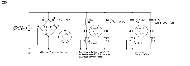
The Wheatstone bridge has been around for a very long time, and can be used to measure (or compare) two resistors, capacitors or inductors. The bridge is also used for strain gauges, and can be extraordinarily sensitive. Unfortunately, the output voltage when used for component measurement varies over a very wide range, meaning that the user has to adjust the gain of the measuring amplifier to get a good null. Should the balance be lost, this can result in a very loud output level, which can be dangerous for your hearing if you are using headphones.
When all resistances are equal (or R1 = R2 and Z3 = Z4), there is zero voltage between 'A' and 'B', so no voltage (or current) appears on/ through the meter. The traditional Wheatstone bridge uses DC, and a galvanometer (a very sensitive meter movement) to detect any imbalance. This has the advantage that the polarity depends on the direction of the error, something that's harder with AC excitation. It can be done (of course), but that requires phase detection, something I chose not to include in the interests of simplicity. Strictly speaking, a Wheatstone bridge is DC excited and only measures resistance. There's a name-change for AC bridges (e.g. Schering bridge for capacitance, Maxwell bridge for inductance), but this is often not made clear (or even mentioned). For simplicity, I'll refer to this project as a Wheatstone bridge, even if the term isn't strictly accurate.
Balance doesn't require that all resistances/ impedances are equal. Provided R1 = R2 and R3 = R4 (or Z3 = Z4) the bridge is balanced, and there's no requirement for R1 to equal R3. If they are unequal (e.g. R3 is twice the value of R1), then balance is achieved when R4 is twice the value of R2. It's this property that was used back in the heyday of the Wheatstone bridge, long before the first multimeter existed. The meter doesn't even need to be calibrated, provided it can show the user when the minimum current has been reached. The value of the unknown resistor (R4) is determined by the value of R1, which was often provided as a precision resistor decade box. This is (and was) more accurate than using a pot with a calibrated dial, but gets expensive fairly quickly if a wide range is needed at close tolerance. Other connections are also usable, and the unknown component can be substituted for R3. I leave it to the constructor or experimenter to decide which arrangement s/he prefers (noting that 'A' and 'B' must be ground referenced).
This project covers the Wheatstone bridge and derivatives, its use in measurement, and also (and especially) describes a logarithmic amplifier that makes getting a good null not only easy, but with greatly reduced amplitude variation. That means you don't need to ride a level control to keep the signal audible (or easily measurable), because the log amp reduces the level change from perhaps 1,000:1 to a more manageable 7:1 (simple log amps are based on natural logs (base 'e'), not base 10). There's nothing particularly new about the idea, but combining the two doesn't seem to be something that anyone else has thought of doing. Several searches revealed plenty of info about the basic Wheatstone bridge, but very little on advanced techniques for the detector. A log amp can also be used with DC, but the blocking cap I included in Fig. 3 would need to be removed, and a method of nulling any DC offset is required.
Most descriptions show DC excitation, but AC is better because it's easy to remove any DC offset caused by 'imperfect' opamps with a capacitor. A good 'general purpose' frequency is around 400Hz, because it's easily amplified with cheap opamps, and is comparatively easy on the ear. In general, I wouldn't suggest more than 2kHz for the circuit described below, and if you're listening to it, a lower limit is around 150Hz. The excitation voltage can be anything convenient. For simulations, I used 5V peak (3.54V RMS), but if it's higher you run into difficulties getting enough voltage swing from the oscillator. Ideally, the source impedance will be low, but it doesn't materially affect operation. 50Ω is fine, and is easily achieved with most opamps (see Fig 8). I've used a sinewave for the descriptions, but you could even use a squarewave if that's all you have available.
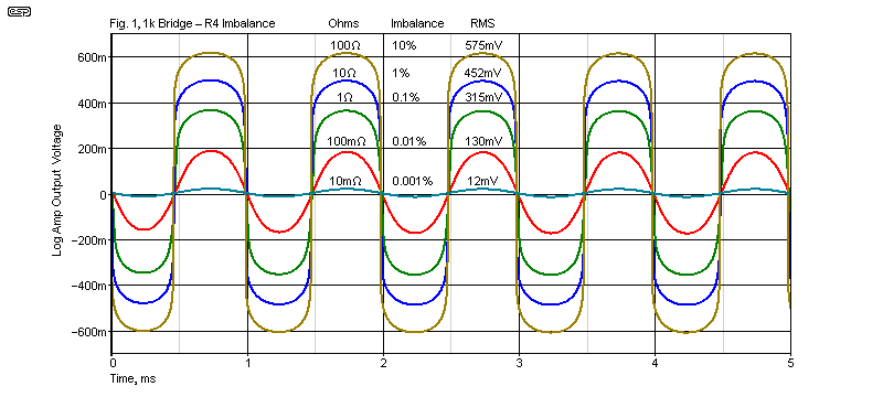
Fig. 2 shows the output level for a 1k bridge with an imbalance of 10mΩ, 100mΩ, 1Ω, 10Ω and 100Ω, as shown in Fig. 1. Without the log amp, the voltage would have been from a minimum of 24.5mV peak with 10mΩ imbalance, to 245V (yes, volts!) with 100Ω imbalance - assuming that an amplifier capable of that voltage were used. Using normal opamps, the output would simply clip at around ±10V or so. With the log amp, the minimum is still 24.5mV peak, but the maximum is 612mV. The input voltage was 5V peak at 1kHz for these tests. For the 1k bridge shown, 10mΩ is only a change of 0.000999% (0.001%), showing how sensitive the bridge can be.
With a log amp of any kind, the output changes by one 'unit' for every 10 'units' of input change. For example, with an input of one 'unit', the output is zero, increasing to 2.3 (one log 'unit') with an input of 10, 4.6 for an input of 100, and 6.9 for an input of 1,000, etc. This assumes natural logs, not base10 logs we normally use. It doesn't work exactly as expected in the circuit described, but it's close.
While I make no claims that the log amp is truly logarithmic, it's good enough. We don't care about absolute accuracy, only that we obtain an output that varies within a sensible range, either for listening or measuring. By including the log amplifier, the range is compressed enough to allow easy measurement down to well below 1% for capacitors, and below 0.01% for resistors below 10k or so. There are limits imposed by the measurement amplifier, which will always have some impedance (especially stray capacitance) to ground, and that will unbalance an otherwise perfectly balanced bridge circuit. The error becomes greater depending on what we're measuring, and the measurement frequency. Stray capacitance becomes a serious issue with high impedances, typically anything over 100k.
By far the most common use for a Wheatstone bridge now is for strain gauges. These are used to detect movement in architectural structures (buildings, bridges, tunnels, etc.) and for weight measurement. Most common weighbridge sensors use strain gauges, which are almost always used in a bridge form (i.e. Wheatstone). For weighing (anything from a cup of flour to a fully loaded B-Double heavy haulage truck), a number of strain gauges (typically four) are arranged into a load cell, which is the basis of most modern weighing systems. The individual strain gauges are organised as a Wheatstone bridge, but with four variable resistances. Load cells are available from major suppliers (usually $$$$) or from online sellers for under AU$10.00. I leave it to the reader to decide which is likely to be more reliable.
Note that this project is not intended to be used with load cells, but that shouldn't stop anyone who wants to play with them. With some modifications, it could be used as a basic seismometer (for example). Even though the Richter scale is logarithmic, the log converter shown here is not even close to being accurate enough! However, it will give you a good indication of small events , and will compress more vigorous vibration without suffering overload. The distortion created will prevent accurate interpretation of the signal, something to bear in mind.
A similar (but far more complex) technique is an analogue limiter (as used for audio). A limiter can be set up to do much the same job, but it needs to be fast-acting, and will require many additional parts, and it will be much more complex. This was the first idea I had for the task, but it was quickly discarded when I realised that it was going to be more difficult to build, for no good reason.
While I've used a Wheatstone bridge as the primary signal source, any situation that requires obtaining a signal null can benefit as well. Null testing is an excellent way to determine if the audio performance on one opamp is different from another (for example), and the same test can be applied to cables, interconnects or a complete amplifier. An example of null testing is described in the article Audio Interconnect Comparisons which relies on being able to get an excellent null - if the cables are comparable. The same technique can be used to compare opamps, but power amps often have some 'excess' phase shift (which isn't audible, but messes up a null test rather badly). This may occur at low frequencies (e.g. different value input coupling caps) and at high frequencies (e.g. compensation networks to ensure stability).
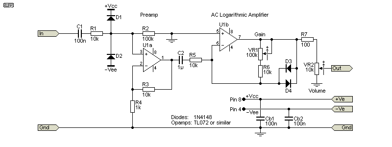
The log amp is shown above. The first stage has a gain of 11, and includes input protection. If you intend to use it as a signal tracer on high voltage amps (valve [aka 'tube'] amps), then C1 must be rated for 600V, and R1 should be increased to 22k. The values shown are fine for general purpose work with transistor or opamp circuits. We need to add an instrumentation amp if it's to be used with a Wheatstone bridge.
The AC log amp is fairly crude, but it does what's needed. A much better version could be built, but at considerable cost and requiring a dedicated IC or ICs. For what's needed, that would be complete overkill, as we just need to limit the maximum amplitude while preserving the null when the bridge is balanced. The circuit described does that admirably, as demonstrated in Fig. 2. The gain of the log amp will need to be reduced for many tests, so I've included a gain pot. With VR1 at maximum, the total gain is 121 (41.6dB near enough).
The general principles were described in the intro, but the realisation of the circuit is another matter entirely. As always, we must make compromises, and these affect the final outcome. Measuring resistance is easy, and extraordinary accuracy can be obtained, especially if we are only looking at balance (i.e. comparing two resistors). AC excitation is the only sensible choice, and that means using an oscillator. Rather than describe something new (or repeating the circuits shown in other projects), I suggest that you look at projects 22, 50, 86, 162, 174, or 179, all of which describe potentially suitable oscillators. Of these, Project 86 is probably the best option, as it's easy to build and more than good enough for this application.
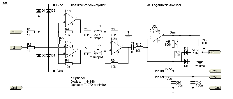
FET input opamps are required - at least for U1a and U1b, because anything else will load the bridge and may cause inaccuracies. The inputs are protected by R1 and R2, and diodes D1-D4. Note that the lower resistors of the bridge must be connected at all times, or the inputs to the instrumentation amp have no ground reference. The gain of the instrumentation amp is 21, which means that the worst-case bridge imbalance will create a clipped output at around 10V RMS. The log amp limits this to about 670mV RMS, a level that's not too outrageous. At maximum gain, the whole circuit has a theoretical common-mode rejection of over 80dB, but only if close-tolerance resistors are used, or you include the trimpots. For perfect balance, you need R3=R4, R6=R7 and R8=R9 exactly!
With a gain of unity, the instrumentation amp (after trimming) has a common-mode rejection of 100dB, which is as good as an AD8221. However, to get this you must carefully match the resistors as noted above. Use of unmatched 1% resistors limits the unity-gain common-mode rejection ratio (CMRR) to something typically no better than 60dB. If your resistors happen to align in the worst possible way (as determined by Murphy's Law), it will be much worse. With 'perfect misalignment', CMRR could be as low as 40dB, which is close to useless. The resistances don't need to be precisely 'on value' (i.e. 10k) but they need to be equal. Two resistors at 9.9k (-1% tolerance) are fine, as are two at 10.1k (+1%) or any value in between.
Unfortunately, the easiest way to get equal values is with a Wheatstone bridge, which hasn't been built yet! The alternative is to use an AD8221ARMZ or similar, but these are not inexpensive ICs, and are SMD only. If you choose to use one of these, refer to the datasheet. It can be substituted for the entire instrumentation amp (U1A, U1B, U2A and associated resistors. R5 is still needed, but the value needs to be changed to keep a gain of 21. Alternatively, you can use a multi-turn trimpot to get the best possible CMRR - test with both instrumentation amp inputs shorted, log amp at maximum gain, and around 2V peak input signal at your preferred frequency. Add a 220Ω trimpot in series with R6 (TP1) and another 220Ω trimpot in series with R7 (TP2) - these are shown as optional. Set one trimpot to 50% travel, and adjust the other for the minimum output from the log amp - it should be no more than 100μV (106dB CMRR). You may not be able to get it quite that good, but if you manage 100dB of CMRR with the normal instrumentation amp gain of 21 (followed by a gain of 11 from the log amp), that's very good indeed. You may need to work between TP1 and TP2 to get the best null. By using two trimpots, you have the capability to correct for a greater offset if it should occur.
The gain of the log amp is 11 at low levels (maximum gain), and once the output voltage approaches 600mV (the forward voltage of D5, D6) it starts to limit. Because diodes exhibit a logarithmic response with increasing current, the peak amplitude shows a log response. With higher inputs to the instrumentation amp it will clip, but the maximum level from the log amp won't go above ~680mV. Refer to Fig. 2 for levels obtained from my initial basic tests. The total gain of the system is 231 (42dB) with VR1 at maximum resistance.
The bridge itself is another matter. You have to decide whether you only need simple balancing (for comparing components), or if you must measure values by making the bridge itself adjustable. The latter is more complex (of course it is), but it will let you take measurements over a range that you can choose. You also need reference components (resistors, capacitors and inductors), although the latter are optional unless you are working with passive speaker crossovers.
Note that the ultimate accuracy (or balance) you can obtain is highly dependent on the accuracy of the bridge resistors, R1 and R2. The exact value is less important than how well they are matched. You can't expect to get matching within (say) 0.01% if you use 1% resistors. You can buy close tolerance resistors from the major suppliers, but they are expensive. Where a standard 1%, 400mW metal film resistor may cost around 40c, the same part with 0.1% tolerance will be at least $2.00, and 0.01% metal film may be over $70.00, but only $17.00 if you choose wirewound. This is where the ability to select parts to close tolerance comes in handy, and it's much easier than measuring each with a multimeter. Of course, if you need to be able to measure 1k with better than 0.1% accuracy, your meter has to be able to resolve 0.1Ω reliably. Most can't.
A standard bridge is as shown in Fig. 1, but R3 and R4 can be replaced by capacitors or inductors. With caps, the lower limit is determined by the capacitive reactance, which should remain at less than 100kΩ. With 400Hz excitation, that sets a lower limit of around 4nF. The input impedance of the instrumentation amplifier will cause some imbalance, even with the 10MΩ resistors specified. These can be omitted if you only measure resistors or inductances, but if you need to measure capacitance they cannot be dispensed with. They can be made larger though, but at the expense of higher DC offset (which is removed by C3) and higher noise. The latter will (hopefully) be reduced by the device(s) under test.
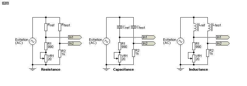
When matching parts, there is a tolerance that must be accepted. In general, 1% is acceptable, but there are often situations where this isn't good enough. With R1 and R2 as fixed resistances, only an exact match between the reference and test component will create a null. However, if a variable resistance is used for R1, that allows you to adjust the resistance to obtain a null. The resistance change is an indicator of how close the parts are. For example, if R1 and R2 are both nominally 1k and you are aiming for a 1% match, you could make R1 variable between 990 and 1,010 ohms. If varying the pot gives a null at some point (including full travel in either direction), then the reference and test parts are within 1% of each other. Should the null occur at 50% rotation, the parts are close to an exact match.
For example, in Fig. 4 B, if Cref is 100nF and Ctest is 100.5nF, the pot will allow you to obtain balance at about 25% of rotation. This can even be calibrated, as 25% of rotation indicates that Ctest is 0.5% high (the pot allows a null at ±1%). If a null can't be achieved, Ctest is outside your target range. Note that for this type of test, you'll probably have to use the log amp at its high gain setting. The null will be very sharp, and you can get close using low gain, then increase the gain for a full null.
If you want to measure (rather than compare) components, the lower resistor (R2) is typically replaced by a calibrated potentiometer. Ideally, this will be wirewound, and even better if it's multiturn (usually 10-turn). Calibration is a serious pain, and while this used to be common for Wheatstone bridge measurement systems, IMO it's not really viable any more. Making the dial is difficult unless you have access to some fairly serious layout software, and a way to convert that to a disc that's used as a 'readout'. Both resistors and inductors have increasing impedance with increasing value, but capacitors have a falling impedance with increasing values. The dial therefore has to have two scales, with one the reverse of the other.
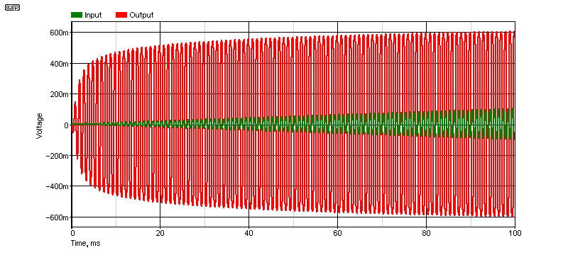
Because the amplifier is deliberately nonlinear, it's worth showing the amplitude response. For the figure below, the input level was increased linearly from 0 to 100mV peak. The output level remains well above 400mV peak with as little as 4mV peak input. Some may feel that even low gain is too high, and for some tests that may well be true. The gain can be reduced even further by adding another resistor or replacing R13 to 51k and R14 to 5.1k. You can use other values if they suit what you're doing. At the extreme, R13 can be a 100k pot, so you can set the gain to whatever you like.
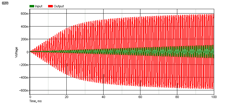
The response with the gain set for ×1 is shown next. The null (zero volts) is still easily seen, but the maximum level isn't as great for the same 0-100mV input. VR1 allows you to set the gain as required for what you're doing. If you need a quick null, that can be obtained with a low gain setting, and the gain can be increased as you get closer to the best null (minimum voltage).
If you think that you may need very high gain, VR1 can be replaced with a 1 MΩ pot, which is useful if you expect to match anything to better than 0.01%. With such a small imbalance, the output null will be very narrow, making it challenging to detect the 'true' null. As noted in the intro, the use of AC excitation is necessary to measure capacitance, but there's no indication as to whether your pot setting is high or low. In reality, it doesn't matter too much, because if you turn the pot one way and the level increases, then opposite rotation is called for.
The default for detection is to hook the output up to a headphone amp (or even a bench amp), but you can just as easily use an AC millivoltmeter. On the off-chance that someone will want to include a meter in the unit, I've shown a simple millivoltmeter below. It doesn't have especially wide bandwidth, but should handle up to 10kHz fairly easily. There's also no real need for accuracy, because you are only looking for a null - the minimum voltage you can get by adjusting the pot or substituting a component.
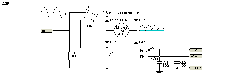
The meter is based on a simple version shown in App. Note 001. It can be calibrated if you wish, simply by adjusting the value of R2. With 1k, the sensitivity is nominally 1mA/ volt (average value), so it matches the output of the log amp well. The sensitivity is (theoretically) independent of the internal resistance of the meter's coil, but as it's only used as an indicator this is of little consequence.
As mentioned in the introduction, you can add a bandpass filter at your preferred frequency that will reduce the distortion to the point where it's barely audible. For more info on multiple-feedback bandpass (MFB) filters, see the Designing With Opamps - Part 2 article. The link takes you directly to the bandpass filter section. The filter design shown is set for unity gain, a Q of 10 and a frequency of
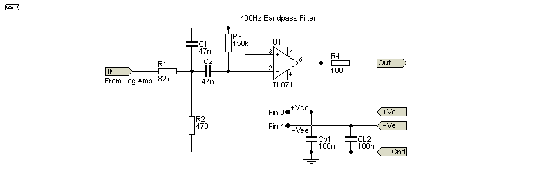
If you add the filter, the distortion all but disappears, but so does the very audible cue that you are approaching a null. I leave this to the constructor, as some people are likely to prefer it, others not. Because it's tuned to 400Hz, you can't change frequencies unless you re-tune the filter. This design is simple, but it doesn't lend itself to easy tuning. A variable frequency filter is certainly possible, but it increases complexity for no real benefit.
I mentioned above that the signal source will typically be an audio oscillator, preferably with an output impedance of no more than 50Ω. If you use a nominal 1kΩ bridge all will be well, but if you decide to try matching moderately high-value capacitors this may overload the oscillator. For example, comparing a pair of 1μF caps in a bridge (e.g. as shown in Fig. 4) presents an impedance of a little over 500Ω at 1kHz, somewhat low for most oscillators. Higher capacitance increases the load. Another issue is that your oscillator may be incapable of providing a 5V peak output, so you either accept the loss of sensitivity or add a suitable buffer circuit. A design is shown next, and it has an output impedance of 50Ω and can drive 5V peak into a load impedance down to around 200Ω or less.
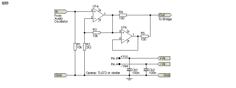
The type of opamp is relatively unimportant, and you can get a bit more current capability if you use an NE5532. We aren't particularly worried if there's a bit of distortion, and even a small DC offset is of little consequence. The gain is 5.54, so you need less than 1V peak (700mV RMS) to get the 5V peak I suggest. The circuit shown is a tried and tested method for connecting opamps in parallel, and each half of U1 shares the load equally. You can reduce the value of R4 and R5 to get a lower output impedance, but I don't think there's much to gain.
I won't describe a specific power supply for this project, as it will work happily with any of those shown elsewhere (e.g. P05-Mini or similar). Any supply from ±12V to ±15V will be perfectly fine. I suggest a supply capable of about 50-100mA (about 3W maximum). The total load will normally not exceed around 20-30mA.
Note that bypass capacitors must be used across each opamp's supply pins, and the supply rails need to be fairly low noise. Inadequate bypassing can cause opamps to oscillate. The bridge amplifier will best be in a grounded sub-enclosure to minimise noise pickup (especially 50/ 60Hz hum). Because the circuit is so sensitive, even a small amount of extra noise will cause problems. The bridge circuit (if that's what you use it for) obviously needs to be accessible, but leads between the bridge and instrumentation amp should be shielded.
Otherwise, construction should be fairly straightforward. The opamps I've specified are cheap and cheerful, but are far more capable than many people imagine. You can use 'esoteric' devices (e.g. OPA2134), but they will cost more for no real benefit. Other types are likely to be even more expensive, but will not improve the performance of the circuits.
You can still buy (more or less 'proper') Wheatstone bridges, with some costing less than AU$200.00 at the time of writing. Most are designed for resistance only, and use DC excitation with a centre-zero moving coil meter to show the null. Despite there being little reason to buy a bridge that can only measure resistance, there are quite a few advertised on eBay and other online platforms. If you need detailed explanations of the Wheatstone bridge, there are countless articles online, with many providing all the maths you'll (n)ever need. A full understanding used to be important, but about the only place it's important now is for people who are working with strain gauges.
Strain gauges are a topic unto themselves, and it would be folly to try to include them in any detail in this project. However, most are still used with DC excitation, making amplification difficult. Very low DC offset opamps are needed (often requiring chopper opamps to null out any DC drift). AC excitation is used in some instances, with some clever techniques to include phase relationships so the output properly represents the applied strain - either tension or compression.
When searching for more info, one thing you probably won't find (I didn't) is any useful reference to AC excitation and the use of a log amplifier to limit the dynamic range. There are applications where a meter reading can be used to determine a value, but this is not a reliable method. As always, a search can either uncover gems or turds - often both  .
If you perform a web search you'll find hundreds of pages describing the Wheatstone bridge. Needless to say I won't repeat them here, but a search engine is your friend. Naturally, not all documents you find are accurate, and (as always) you'll need to work out which is useful and which is not. Fortunately, there aren't many things one can get wrong when it comes to simple circuits.
The second reference will be invaluable for anyone wanting to explore bridge systems in depth. It covers a lot of what you'll need to know if this is your chosen adventure. At 77 pages, it's no lightweight discussion. Other major manufacturers will have similar detailed analysis material, so it's worthwhile searching their archives.
| Main Index
Projects Index
|