
|
|
| Elliott Sound Products | Project 262 |
In any valve (vacuum tube) amplifier, there is one power supply that is more important than any other, and it's the one where most manufacturers seem to try to outdo each other to determine the worst (but cheapest) possible circuit. IMO this is madness. Should any part of the circuit fail or be compromised in any number of exciting ways, there's every chance that you'll lose the output valves due to severe overload, and you may even damage the output transformer. In most cases, the HT (aka B+) fuse will fail, but if it's been 'upgraded' that may not happen. A shorted output valve can even destroy the mains transformer if all fuses aren't what they are meant to be.
I don't know of any valve amp that won't allow the B+ to be delivered unless the bias voltage is present, but this is not at all difficult to achieve. Yes, it requires a bit of circuitry and a dedicated power supply, but it could be added for well under AU$10.00 at the time of manufacture. Output valves (actually all valves now) are expensive, so protecting them is well worth the small extra cost. Fender goes one further - there's at least one amp (Super Sonic 100) that includes a bias computer, but if a failure is detected, it can't shut down the B+. Despite all the extra technology they throw at the bias control circuit, it still uses a ½-wave rectifier, despite the use of a separate winding.
Two things are critical. The first is ensuring that the bias supply comes up quickly (ideally in less than 1 second), and the second is ensuring that it collapses slowly. With the shitty bias circuits by most (guitar amp) manufacturers, the opposite is true - the bias rises slowly and falls quickly. This is the opposite of what's needed.
Another factor that's often not addressed (or is addressed poorly) is the overall impedance (mainly resistance) of the bias output. It must be low enough that the voltage doesn't add significant resistance to the valve's grid bias resistor. These are often at the valve manufacturer's absolute maximum value, so any leakage on the valve base can easily reduce the bias voltage enough that one or more valves are operating past their maximum dissipation (aka 'red plating').
You'll often see claims such as "Since negatively biased grid draws no current, an adequate bias supply is a single diode charging a single capacitor. The capacitor is charged to peak voltage and maintains it. There is no ripple. This circuit was used in many commercial fixed bias amplifiers, for example Scott." This is (predictably) bullshit! All bias circuits have an adjustment circuit, and that does draw some current. One part of what's been ignored is the absolute requirement for a low resistance to ground (a point missed by many!).
A search for "tube negative bias failure detector" yields plenty of results, but none for an actual detector. Just countless websites and forum pages discussing bias circuits in general, some of which are an accident waiting to happen.
Note that this article does not discuss 'tone', as the negative bias supply should not contribute to the performance of any amplifier, provided the voltages are set correctly for the expected valve plate dissipation. 'Tone' is also a pretty meaningless term, as it means different things to different people. That makes it intangible, and what it means to different people can be confusing. For this reason, I rarely discuss 'tone' other than when describing the response of EQ circuits (e.g. bass, middle, treble).
Some amplifiers have (or have been fitted with) a bias monitor, that verifies that the output valve current is either within a defined range or below a set maximum. This is fine, and was the first method I contemplated for this project. However, such a design requires an averaging circuit that slows down the reaction time, and it cannot act quickly enough to avoid valve damage or blown fuses. If such a circuit is to disable the B+ supply, it still needs a relay, and any circuitry you add needs a power supply.
There have been a (small) few published designs, with a common method being to monitor the cathode current with a resistor, and detect excess cathode current. This can trigger an SCR (silicon controlled rectifier) that operates a relay to disconnect the B+ supply. While such a technique will certainly work, it will only operate with a potentially catastrophic failure, and the circuit must be set up so that normal peak current at full power doesn't cause the circuit to trigger. Typically, 10Ω fusible resistors would be installed in each cathode circuit (to ground), and the SCR detects any excessive voltage developed. IMO, these resistors should be fitted as a matter of course to allow easy bias adjustment.
Assuming a pair of EL34 valves in push-pull with a 400V supply, the maximum cathode current is the sum of the plate and screen grid currents (110mA and 23mA respectively, full power). The protection circuit could be set to trigger if the cathode current exceeds 113mA, but that's too close to normal operation, so we'd probably go for around 130mA (1.3V across 10Ω). However, a degraded bias supply will not be detected, so the valve(s) could dissipate far more than their rated plate power without the protection circuit operating. Personally, I don't think that's good enough.
The same calculations can be used for any of the common output valves, such as EL84, 6V6, 6L6GC, 6CA7, KT66, KT88, 6550, etc. The actual (as opposed to datasheet) values will differ, depending on the design of the amp's output stage. Getting an SCR to trigger at a specific level isn't easy, because the gate trigger voltage is variable, so additional circuitry is required to provide a predictable setting that isn't dependent on the temperature inside the chassis or the specific trigger voltage of the SCR used - this is not a 'guaranteed' value. For example, the BT169 (low power SCR) has a gate voltage between 0.5 and 0.8V. These are not precision parts.
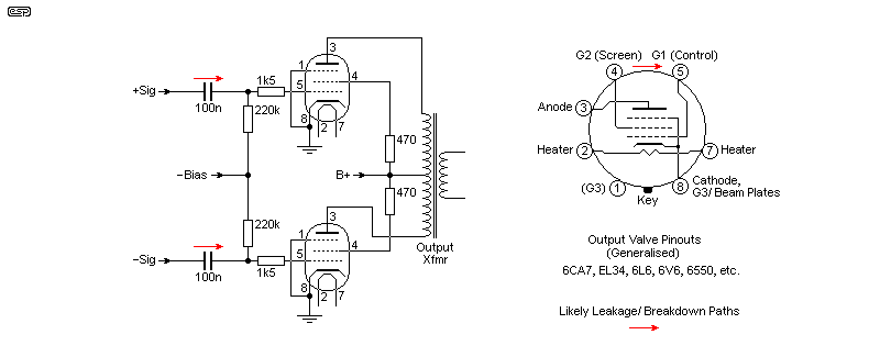
Ignoring (for the time being) the bias circuit itself, there are two main paths for leakage or even breakdown. Input capacitors can become leaky, or the fibre/ turret board they're mounted on can become leaky (there have been several manufacturing 'runs' where the fibre board was no good, and it would absorb moisture and leak like a sieve). The valve base or its socket can be subjected to excessive voltages (e.g. if the amp is run with no speaker plugged in), causing the Bakelite to break down and turn to carbon. The most common area for this is between pins 2 and 3. However, if contamination or other conductive residue gets between pins 4 and 5, expect some seriously bad things to happen!
There are two ways to bias output valves in instrument (e.g. guitar, bass, etc.) and hi-fi amps. Cathode bias (aka self-bias) uses a resistor in the cathode circuit, and it's essentially self-correcting. Cathode bias is used in all preamp stages, and often with relatively low-power amps, no more than 30W or so. It's also the most common approach with Class-A operation. Single-ended amplifiers almost always use cathode bias.
Fixed bias is most common in high-power (> 50W) push-pull amplifiers, and it relies on a separate negative supply that sets the control grid voltage to a suitable (negative) level to eliminate crossover distortion, while keeping the plate dissipation to (ideally) between 50% and 70% of the maximum allowable. The bias supply is critical to ensure that valve dissipation is well controlled. Failure will result in the output valves turning on as hard as they can, leading to fuse or valve failure (or both), and sometimes damaging transformers as well.
Therefore, without doubt, the negative bias supply is the most critical in any valve amp. Some amps are very poorly designed, with a bias supply that takes a month of Sundays (well, up to 5 seconds to be accurate) to come to full voltage (e.g. -40V), but drops to -30V in less than 0.4 second. This is taken from a real amplifier from a well-known maker, and isn't some fantasy I 'invented' for dramatic effect.
With some amps, all that's needed to make the (internal) HT fuse to blow is for the mains lead to be disconnected momentarily or for the amp to be switched off and back on again within a few seconds. The bias collapses almost immediately, and when power is restored the B+ supply comes up to maximum very quickly, but the output valves (with cathodes still hot) have almost no bias. They conduct fully, and the fuse does not survive. The valves will suffer some damage as well, as they aren't designed to conduct over 400mA each (commonly EL34/ 6CA7 or 6L6 type valves, but this will happen with any valve).
Of all the places to penny-pinch, the bias supply is by far the worst, and the designer of such bias supplies (and I use both terms very loosely indeed) should be taken out and shot! Many are a travesty, and should never have happened, but they are out there and catch out musicians regularly. If there's no retaining clip for the IEC mains input, it's all too easy for the lead to be pulled out and quickly replaced during setup. The player has no amplifier for the gig if that happens! Where fitted, the HT (B+) fuse is often internal, so the amp must be dismantled to replace it.
Apart from ensuring that the bias supply is as good as it can possibly be, there can also be a case for installing a detector that removes the HT supply if the bias voltage is too low. For a -40V bias supply, the HT should be disabled if the bias voltage drops below (say) -35V. This will prevent valve damage and the not inconsiderable angst caused when the amp fails and destroys a pair (or two) of expensive output valves for no apparent reason.
One thing I really don't understand is why almost every valve amp maker uses a half-wave rectifier for the bias supply. Even when there's a separate winding on the transformer, you'll still find the ½-wave rectifier (one diode), despite that fact that diodes are so cheap! The current required is negligible, but a full-wave (bridge) rectifier just makes the bias supply that much more robust, and it reduces ripple. There are exceptions of course - I've come across a couple of guitar amps that use a full-wave rectifier for the bias supply, but even those were (IMO) seriously under-designed. The most common issue is too little capacitance, so the bias voltage collapses too quickly when power is removed.
Many Fender amps have a separate tap on the HV winding for the bias supply. Because it's a tap (not a separate winding), you can't use a full-wave rectifier, but at least it's a little better than a resistive or capacitive dropper from the full HV output. The two circuits shown below are examples, but both manufacturers have switched the way they derive bias any number of times. The Fender circuit is often simplified even further, with R2 and C2 omitted. Either way, it's quite apparent that very little consideration was given to the designs, other than to minimise the cost. Note that the 220k resistor in the Marshall style circuit is subjected to a high voltage, typically well above the resistor maker's specification (yes, resistors have a maximum allowable voltage). It should be a 1W resistor or two resistors in series to limit the voltage. This is done ... sometimes.
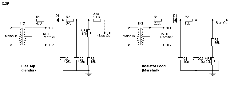
There are several different schemes used, with the vast majority using ½-wave rectification. This is suboptimal for a variety of reasons, but very few amps have used anything else. The Fender arrangement is asking for trouble, because, if the bias trimpot's wiper disconnects (due to age, wear, or because it can), bias is removed completely. The extra resistor shown as 'add' should be considered non-negotiable. The Marshall circuit is high resistance, and it takes longer to develop the bias voltage than it takes for the caps to discharge. As shown, -35V bias (-42 nominal) is achieved in 2 seconds, but it only takes 220ms for it to collapse to -35V. Within 2 seconds there is effectively no negative bias at all (about -6V)! Who thought this was a good idea? It takes 5 seconds for the bias to reach -40V. Both circuits collapse to around -15V in less than 1 second.
A single resistor (typically around 220k) is often used from just one transformer HV winding, leading to a very slow bias voltage and an undesirably high supply impedance. This is common with most Marshall amps, while Fender most commonly use a tap on the HV secondary winding. Capacitor-fed bias circuits are also used, but invariably ½-wave. The caps must be rated for continuous AC operation, so Class-X caps are preferred but rarely specified. There are many variations, including a separate power transformer winding used by some manufacturers, but almost all remain half-wave  .
.
There's 540mV peak-peak of ripple (174mV RMS) on the Marshall bias supply, and 1.07V P-P (326mV RMS) on the Fender variant (both set to -40V). In theory, and with perfectly matched valves, you won't hear any hum/ buzz, but I consider that much ripple to be excessive. Even on amps that have a separate bias winding, the rectifier is mostly still ½-wave and the capacitors are too small. It doesn't take much effort to make a much better bias supply that will add very little cost, but the makers would rather save a few cents! Note that neither circuit provides the ability to separately bias each valve, but some amps have a 'balance' control and a few others have separate pots for each output valve. This is the preferred option, but the wimpy bias circuits have to be upgraded to feed the separate adjustable bias dividers.
In many places, you'll see the output valve G1 resistors referred to as 'grid leak' resistors. This is wrong! Grid-leak biasing is (or was) sometimes used in preamp circuits to remove the cathode resistor and its associated bypass capacitor. It is a completely separate idea, and referring to the G1 resistors as 'grid leak' is discouraged because it does not describe how fixed bias works.
It's worthwhile to show how you can modify the bias circuit to make it more robust, and have lower ripple. The following circuit is based on the use of capacitive 'voltage droppers', which don't dissipate any heat. Half-wave versions are sometimes used in commercial amplifiers, but caps cost more than resistors so it's not as common as resistive droppers. This arrangement is typically used with a full-wave rectifier (having a centre-tapped secondary). It can generally provide higher current without excessive power dissipation, but capacitor reliability is critical. Should the cap fail (or have reduced value due to progressive internal failure), the bias voltage falls, and that can cause severe valve overload. The user may not even notice unless s/he looks at the output valves and sees they are 'red-plating'.
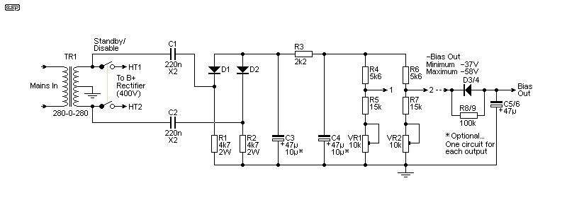
Lacking a separate winding on the power transformer, the above is an arrangement that you will probably never see in practice. It's far better than a simple half-wave, and dropper capacitors are better than resistors (no wasted heat). Further examples of bias supplies are shown in the article Valve (Vacuum Tube) Amplifier Design Considerations - Part 2 (section 9), along with preferred options and a discussion of the importance of the bias supply. The supply shown has much lower ripple (just under 5mV peak-peak or ~1.8mV RMS), but it still doesn't have a wonderful hold-up time because the feed impedance remains higher than desirable to allow for (much) larger filter caps. Maximum current transfer occurs when the reactance of the feed caps (C1 and C2) is equal to the value of the load resistor (R1 and R2). The reactance of a 220nF cap at 50Hz is a bit under 15k. If the load resistor is made greater or smaller than the optimum, the bias voltage decreases. By using larger caps (C1, C2) and lower value resistors for R1 and R2, the overall source impedance is lowered, while retaining the required voltage.
The full-wave bias supply shown has fairly a low impedance, and it will reach a voltage of -35V in around 0.8 second. This is much better than a half-wave version, but it's still suboptimal. The decay is still fast, because the output is loaded by the bias adjustment networks. The bias network(s) must have relatively low overall resistance to ensure bias stability (and minimise the G1 to ground resistance). Increasing capacitance to improve hold-up time makes the circuit take longer to reach the proper bias voltage. Any valve grid leakage is discharged into a fairly low impedance part of the supply. Ripple from the supply shown is under 2mV. Ideally, the bias supply will have a dedicated (full wave rectified) transformer winding, allowing for much faster response, lower ripple and a longer hold-up time. Note that different values will be required in Fig. 3 if you need more or less negative bias.
Quite a few manufacturers have thrown away the opportunity to get a robust, low impedance bias circuit. Several have used a separate bias winding on the power transformer, but almost no one has ever used a full wave (or bridge) rectifier. It's almost as if they assume that there's some 'magic' in the half-wave version. There isn't, and it's just penny-pinching (although they did pay extra for the transformer winding, then promptly discarded the very real potential benefit!). A (small) number of people have suggested the use of a bridge rectified bias supply, but most assume half-wave as a matter of course. So far, Orange is one of the few makers I've found that used a full-wave rectified bias supply (but not on all models), along with Ampeg (but again, not all models).
The rapid voltage collapse is due to the exponential voltage decay of the filter/ storage caps. If you could use a few millifarads (e.g. 10mF or 10,000uF) you can get a nice, slow decay, but it will need some serious current to charge that in under 1 second. Even with a 400mA charge current, it takes over 1.5 seconds to charge a 10mF cap to 35V from a 42V source. A separate winding can provide that easily because it's transient. However, a 10mF cap rated for 100V is a big (and expensive) component, so don't expect to see anyone adding that to a valve amplifier. Yes, you get a nice slow decay (about 17 seconds for the voltage to fall to -35V for a -42V supply), but it's quite impractical.
A simpler method (but not as good) is to use the parts shown as optional in Fig. 3. The diode conducts if there's any grid leakage, and it maintains a low impedance to ground. The extra resistor and cap provide a longer bias voltage decay time. It's still not wonderful, but it is an improvement over the basic circuit. For -42V bias, it reaches -35V in 850ms, and collapses back to -35V (when powered off) in one second. Still far from ideal, but better than 'standard'. 100/ 120Hz ripple is almost non-existent (less than 20μV).
Having created a bias supply (whether optimal or otherwise), we now need to monitor it to ensure that B+ cannot be applied until the bias is present and above a reasonable threshold. This requires a simple power supply, a comparator circuit and a switching arrangement to disable the B+ supply until bias is present. As far as I'm aware, this is the only such design you're likely to find on the Net. The more feeble the bias supply (e.g. high-value resistor fed, or capacitor fed with mediocre caps), the more reasons you have to build this circuit. High impedance bias circuits are subject to filter cap leakage, which can easily reduce the bias voltage to dangerous levels.
The heart of the project is a bias comparator. It detects when bias voltage is present, and that it is more negative than the preset value. The principle of a bias comparator is simple, but there are a couple of interesting challenges that have to be addressed. Of these, getting a suitable supply voltage for the comparator circuit is the most irksome, because 'pure' valve amps don't have a low-voltage (e.g. +12V) supply that can be used. There are also some 'tricky' situations that may arise, and these are also covered. However, before fitting (and relying on) any protection scheme, upgrade the bias supply with high-quality parts, rated for the voltage they'll be subjected to. Get the best 105°C filter cap(s) you can - this is not an area to try to make a saving!
The general idea is shown below. U1 is the comparator, and it senses the bias voltage via R1. When the bias reaches the preset threshold, the current through R1 and R2 is equal, and the inverting input of U1 falls to zero (set by VR1). The output swings high, turning on Q1 and operating the relay. Until the bias voltage reaches the threshold voltage there is no HT, and if the bias should fail (or fall below the preset) the HT is turned off.
Note:
This allows for a condition where a particular failure may cause the bias detector to cycle, so if 'flash-over' is something you expect, then you have a greater problem than this circuit can solve easily. What is the problem? Sometimes, a valve base (or socket) may arc, joining B+ (usually from the screen grid) to the control grid. With most bias supply circuits, their impedance is so high that the current through the grid-bias resistor defeats the bias, causing all valves to turn on hard. With the circuit shown below, that will turn off the B+ so the fault is cleared. However, once the circuit detects that bias is normal, B+ will be turned on again. This type of fault usually causes the fuse to blow (generally violently). It's not possible to account for all possibilities, but momentary flashovers aren't especially common.
Another fault that can cause re-triggering is a leaky output valve coupling capacitor. Any leakage forces the bias voltage to become more positive, turning the output valves on harder. When the detector sees that the bias is too low, it turns off the B+ supply and the fault goes away! The only way that the amp can be prevented from powering up again (which will cause the detector to detect the fault again) is to provide a lockout circuit. While this does add more parts, it's well worth it. The lockout will keep the B+ supply shut down until the amp is power-cycled (turned off then back on). The lockout will never occur during normal operation, so won't impact performance.
The alternative (and IMO best) option is to switch the mains off if bias doesn't reach the minimum you set, and if there is a fault, turn off the B+ and mains supplies. This prevents the circuit from resetting, and disables the amp if anything untoward happens in use. Yes, it's brutal and stops the amp, but hopefully it will do so before expensive valves are damaged. As long as the fault is present (or reoccurs) the amp remains disabled. Without protection, it will still be disabled, but more damage is done the longer you try to work out what's wrong.
Another obstacle is just how to interrupt the high voltage (B+) voltage. Trying to break the DC is not recommended at all, so for most amps we might need a pair of relays to break the AC going to the rectifiers. Even this is hard, because most common relays are only rated for 250V AC, and we can have as much as 450V AC (for a nominal +600V supply). Fortunately, it's easy to get double-pole relays and use the contacts in series. Alternatively, a MOSFET relay (e.g. Project 198 or Project 245) can be used in the DC line, so there is no possibility of an arc. Only one high-voltage MOSFET is needed because DC is unidirectional.
Series EMR (electromechanical relay) contacts will typically give a contact rating of 500V AC. If the amp uses a bridge rectifier only one relay is needed, but it still requires that contacts are used in series to get the voltage rating. With a full-wave rectifier (centre-tapped secondary), the relay can be placed after the diodes and before the first filter cap. Otherwise, you have to use two relays, one for each winding. While the relay contacts are subjected to DC, it's pulsating, falling to zero 100 (or 120) times a second. This will help to extinguish the arc.
Some valve amps use a voltage doubler to get the main HT and a half voltage rail that powers the screen grids and preamp circuits. These also only need a single relay, but series contacts will almost always be needed except for low-power amplifiers having an AC output voltage of less than 250V RMS from the power transformer. The switching circuits are covered below.
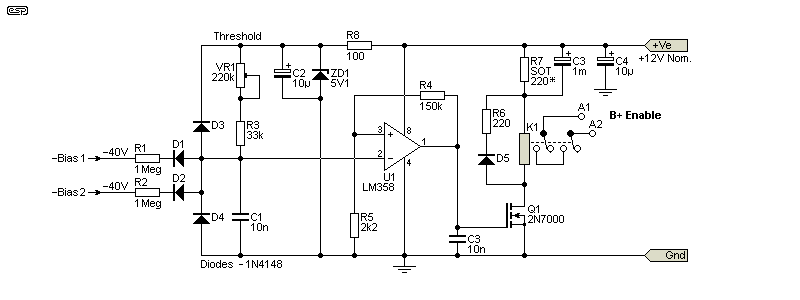
The bias comparator is interested in only one thing - is bias present and above the minimum allowable? The positive input (Pin 3) of the opamp is at close to ground potential (zero volts up to ~80mV). When there is no bias present, the inverting input (Pin 2) is close to the supply voltage. As the bias voltage becomes more negative, Pin 2 is pulled low, and when it falls below ~80mV, the output of U1A (Pin 1) goes high, turning on the MOSFET (Q1) and engaging the relay. This turns on the main HT supply (B+). Using an LM358 dual opamp means that one section is unused, but that's of no consequence (simply connect the unused input pins to ground). These opamps are dirt cheap, and can function just fine with as little as a 5V supply.
I'd prefer to have a ~12V supply for the comparator, but in most cases you will be limited to less (around 7-9V or so), and that makes a 5V relay necessary. I suggest 'sensitive coil' types, which will draw around 80mA (vs. around 120mA for standard types), but the relay current will reduce the total voltage when it engages. By including an 'efficiency circuit' (R6, C3), the relay can be powered directly from the (nominal) 9V supply, so the regulating zener doesn't need to allow for the relay current. R7 is a special case. Its value should be 220Ω as shown, which will allow a peak voltage of a bit over 18V to be developed across Q1. It allows the relay to release much faster than it would with the diode alone. This is important, because we want to remove the B+ as fast as possible, and the resistor lets the relay drop out in perhaps 3-5ms instead of 10-20ms which happens with just the diode.
The negative bias voltage is monitored by U1, and the trigger voltage is set using VR1. In most cases, it can simply be set so that when the bias voltage is greater than (say) -35V, the HT can be turned on. Depending on the design, -35V may allow significant valve current, but it will not be destructive because it's short term. This is suitable for any amp biased with around -40V. The threshold is adjustable, so it can be set for almost any amp design you're likely to come across. During a normal power-on sequence, B+ will usually be enabled well before the valve heaters are up to their operating temperature.
The resistor shown as 'SOT' (R6) drops the voltage to the relay, and its value depends on the relay used. C3 (1,000μF) allows the full voltage to be applied at the moment of switch-on, but lets the continuous relay coil voltage to fall to around 3V - this is often called an 'efficiency circuit'. A more-or-less typical sensitive-coil 5V relay will draw around 80mA. A 12V relay is preferred though, and will draw around 44mA (less with the efficiency circuit - around 20mA).
The ideal is to use the relay to switch the incoming mains. A second relay (normally closed contacts) is needed to bypass the normally open cutout relay when power is first applied, and the bypass needs to be closed for long enough to ensure that the bias voltage reaches the threshold. This could require up to 10 seconds to be safe. Should the bias collapse for any reason (after the bypass relay has opened), the protection relay will open, disconnecting the power transformer. This provides its own lockout function, so the Fig. 3 circuit is the most appropriate. The counters are redundant and the Fig. 12 circuit is not appropriate. This is the safest way to protect an amplifier against bias (and subsequent valve) failure, and it's the method I'd use if I were building a valve amp.
The timer is an extra piece of circuitry though, so it makes for a potentially messy installation. Both the timer relay and its bypass relay must be installed after the power switch, and while the circuitry isn't complex, it does have a certain nuisance value. Note that to remain sensible if you use the transformerless PSU shown below, the relay will need a 24 or 48V coil to minimise the current needed. These are readily available.
You can omit the B+ relay, but there is a disadvantage with this arrangement in that there is a delayed protection against bias failure. When power is applied, B+ will turn on, regardless of whether there is bias available or not. This is mitigated by using three relays - one for the bypass relay (K3), one to bypass the input timer (K2, as shown below), and the last (K1) to turn on the B+ supply. Neither K1 nor K2 will activate if there's a fault at power-on. They both only turn on when bias is present and greater (more negative) than the preset voltage. K1 and K2 are both operated by the bias comparator circuit (Fig. 4). This is the safest way to use the circuit, as it provides complete protection against bias failure for any reason. If the bias doesn't come to the preset level (e.g. -35V or whatever is needed for the amplifier), B+ is not applied and when the bypass timer expires the mains is disconnected from the transformer primary. Note that you must use two separate relays for K2 and K3 to ensure proper operation - there should be at least two seconds of 'overlap', where K2 closes before K3 opens. It might look as if a single SPDT (single-pole, double-throw) relay would work, but it won't.
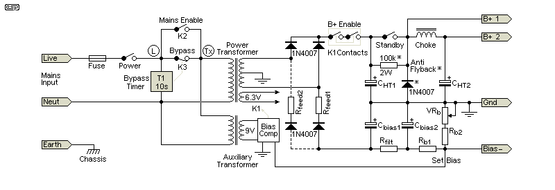
Disconnecting the mains when a fault is detected is absolutely the safest way to arrange the circuit, and a timer is needed to open the mains bypass relay (K3) once proper the minimum allowable bias condition has been reached. The normal B+ voltage is disabled during this time via K1, and if the timer is set for about 10 seconds, this will allow enough time for most bias circuits to reach the bias threshold voltage. If you have a properly designed bias circuit that gives full bias in under 1 second (e.g. a dedicated power transformer winding) the bypass relay delay can be reduced. The three relay method ensures that B+ is not be applied if there's a fault in the bias circuit, and it (and the mains) will be turned off if bias fails in use.
The circuitry of the bypass timer is shown below. It's fairly straightforward, but the timeout must be repeatable, so aiming for super-simple is not an option. Using a 48V relay coil minimises the current requirement (especially if you use a 'sensitive coil' type), with most needing less than 10mA (vs. ~44mA for a 12V relay). The bias circuits I showed above can take up to 10 seconds to reach -40V, other than the one driven from a dedicated transformer tap (less than 250ms). The bypass timer must allow mains through the bypass relay until bias is available and the main B+ relay operates. As shown, it will operate in about 10 seconds (change R2 to adjust - higher resistance, longer timeout).
Note that the above drawing shows another (optional) way to get full-wave bias rectification using two resistor feeds (Rfeed1 and Rfeed2), one from each end of the transformer HT winding. Some may consider this to be a better option than using capacitive droppers, and it's certainly cheaper. The series resistance for each diode is doubled compared to the standard resistor-feed Marshall scheme for the same bias voltage. The full-wave version has the advantage that you can use smaller bias smoothing caps, because the ripple frequency is doubled (i.e. 100 or 120Hz). Also included are the anti-flyback diode and resistor (identified with a *) around the standby switch (only required when a choke filter is used). These should be fitted as a matter of course, but I've yet to see them included in any commercial amp. Naturally, these are not needed if the amp doesn't have a standby switch, but they are a must if you use a MOSFET relay in the DC line.
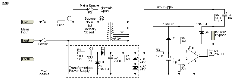
The timer can use a more-or-less typical 'transformerless' power supply, but everything is at mains potential. These are hugely dangerous, but this arrangement is ideal for the application, provided you are careful to ensure that no part of the circuit can be touched when it's installed. If you use a separate transformer to derive a 12V supply for the bias comparator, you can power the bypass timer from the same supply. The relay (K3 in Fig. 5) will be 12V instead of 48V, and the 12V circuit is shown next. Timing is only slightly affected by the change of voltage, so if 10 seconds is right for your amp, no changes are needed.
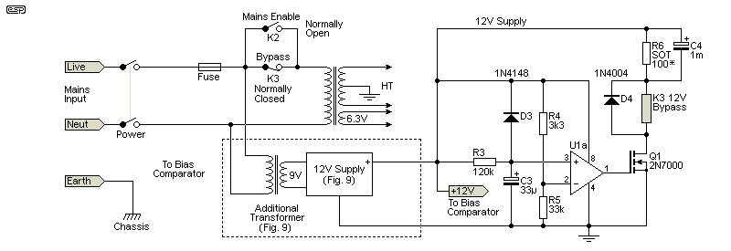
Fig. 7 shows the preferred version. This is another good reason to include a separate 12V supply, as all circuitry can use a common power supply and be on a single piece of Veroboard, other than the relays. They have too much voltage across the contacts to allow the use of Veroboard. A small switchmode supply is by far the easiest to implement, but a linear supply will work. Note the change to the way the opamp gets its supply voltage, depending on whether you use a 48V or 12V supply.
If you use a separate 12V supply (conventional or switchmode), U1 in Fig. 7 will be U1B, with the 'A' section used for the comparator (Fig. 4). Note that the IC pin numbers will change if this is done. The overall complexity of the circuit is reduced fairly dramatically with this arrangement, using a single dual opamp, the minimal comparator shown in Fig. 4, and the simple timer shown in Fig. 8. There are 3 relays, with one to disable B+, one to keep the mains on after the timeout (bypass), and one for the timer. Only the B+ Disable relay requires the contacts in series.
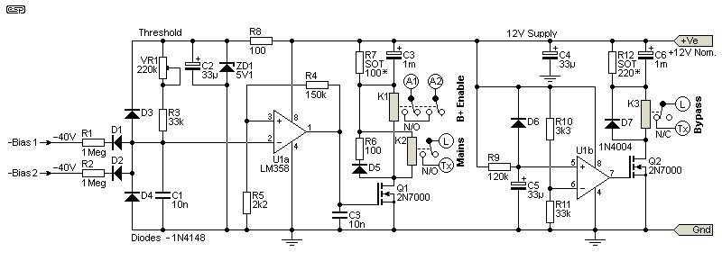
Because it may be difficult for some people to combine the circuits, I've done that for you. This will only work with a separate 12V supply, and even using a 6.3V winding won't work because the load with up to 3 relays energised at once is too great. In operation, only two relays are active, as the Bypass relay drops out after about 30 seconds. Along with the efficiency circuit, the total relay current will be around 50mA for the two relays that are normally closed (K1 and K2). K3 (Bypass) is only active while the circuit settles and normal operation is established (i.e. bias is available and no faults have been detected). It will normally be set up so that it remains closed just long enough for the bias comparator to detect that bias is present. If there's a fault as soon as B+ is made available, K1 and K2 will open, disabling the B+ and de-energising the mains relay. When K3 operates (opening the contacts), mains power to the amplifier is removed completely. The circuit itself remains powered on, but all relays will be de-energised.
It's up to the constructor, but it's possible (although not really recommended) to omit the B+ switching. If there's a fault, the output valves will have to discharge the main filter caps, but the charge held is unlikely to cause damage because it's transient. Unless you switch the DC side of the B+ (not shown above and it must using a MOSFET relay) the main filter cap(s) have to be discharged by the output valves anyway. This will result in a high current and high instantaneous dissipation, but (within limits) valves can handle the peak current easily. After all, this is what will happen if the amp is simply turned off, because the bias supply almost always collapses very quickly. However, using a B+ relay prevents the high voltage from being provided until the bias voltage has reached the preset threshold.
By omitting the B+ relay, you just have two relays with their terminals wired together, being very careful to ensure that the Bypass relay uses the normally closed (N/C) contacts, and the Mains relay uses normally open (N/O) contacts. Note that you cannot just use a single relay and utilise its N/O and N/C contacts, because there must be an overlap to ensure reliable operation. For the minimal extra cost, I suggest that you use both a mains and B+ relay.
Ideally, a 12V relay will be used. While you can (in theory) use 5V relays, their coil current is typically around 100mA each, and that places a heavy load on the power supply, especially since two may be needed. By comparison, 12V relays draw around 44mA, and that's a much easier load on the supply. There are 'sensitive coil' types that can be used instead, but they are more expensive and usually harder to get. The higher the load on the supply, the harder it is to maintain an acceptable voltage to ensure reliable deactivation if there's a fault. This is not an issue if a small extra transformer is added (e.g. a 9V secondary for a 12V supply), but if you're stuck with a 6.3V winding it's much harder.
Many amps still use a full-wave rectifier (centre-tapped transformer secondary), and how it's switched depends on the way the bias is derived. If the bias supply comes from one (or two) of the HT windings (using resistor or capacitor feed to the bias supply), you need two relays if you want to break the AC input. For a bridge rectifier or a voltage doubler, you only need one relay.
The relay must be a double pole type, with the two contact sets wired in series. This is needed because the available voltage is far higher than most common relays are rated for, and series contacts will allow you to break up to 500V RMS. Make sure that you test this thoroughly, and never try to disconnect the smoothed DC supply. Attempting to do so (even with series contacts) will almost certainly just cause an arc, without disconnecting the B+ supply, but possibly burning away the contacts if the arc is maintained. Make sure that the bias take-off point(s) are connected directly to the transformer output(s), so that the connection(s) to the bias circuit is/ are maintained even when the B+ is disconnected. This doesn't apply if the bias is derived from a separate tap or has a separate winding. If you have no choice but to break the DC supply, a MOSFET relay is the only viable option.
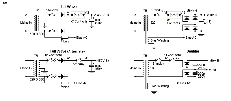
As shown in Figs. 4 & 5, the relay contacts are mostly wired in series to ensure that the voltage doesn't cause an arc when the contacts open. As mentioned earlier, you can use a MOSFET relay, but there's really nothing like the security of an EMR in safety-critical roles. This entire project is intended to be (relatively) low-tech, while providing a level of protection that you don't get any other way. A cautionary note is needed here. When a bridge rectifier is used with a dropping resistor or capacitor, the bias voltage will disappear if either transformer lead is disconnected. This isn't an especially common way to derive B+ and bias, but you need to be aware of the limitations if that's what's used in your amp.
Where a bridge rectifier or voltage doubler is used, a separate bias winding will almost always be provided. This is because opening one side of a bridge/ doubler removes any possibility of getting a stable bias voltage via resistive or capacitive voltage droppers. A very poor 'work around' for this problem is to use the filter cap(s) and associated bleeder resistor(s) as a partial load for the winding. This doesn't work well, and most amp makers avoid it. The examples shown above are just that - examples. There are many different arrangements used, but the above will give you an idea of what's involved.
I did find one Marshall design that used a bridge rectifier for the B+, and a capacitor-coupled bridge for the bias supply. This is a very unusual arrangement, but it does allow the B+ to be disconnected without disabling the bias. However, it still has issues, in that the bias voltage rises quite dramatically when the B+ bridge is disconnected. It's a sufficiently obscure arrangement that few people will be affected.
As noted earlier, you could use a MOSFET relay (such as the Project 198 or Project 245 design), using high-voltage MOSFETs. To make life easier, this can be used in the DC supply, but be aware that if you break the DC before the filter choke you may get a back-EMF from the choke that can exceed the voltage rating of most common MOSFETs. This depends on many factors, and varies depending on the manufacturer. This back-EMF can exceed -5kV easily, limited only by the arcing voltage across the switch. As noted in the article Valve Circuit Analysis (section 9), a pair of diodes or a diode and resistor as shown here, will suppress any back-EMF. This is essential with a MOSFET switch/ relay. There's no good reason not to include it with any standby switch or fuse in the DC line before the filter choke.
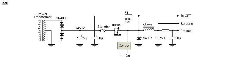
If you do decide to use a MOSFET relay (or some other MOSFET switching mechanism), the diode and resistor are very important. The diode is a 1N4007 or similar type, and it effectively removes any back-EMF from the choke and/ or the output transformer. Personally, I think they should be fitted as a matter of course to any switch or fuse in the same position. The resistor in parallel with the switching is not optional. For the sake of a few cents it's worth including, even though its effect is not great. With 'perfect' inductors, it damps any tendency towards oscillation, but with 'real' ones it's still worth including, if only for peace of mind.
I've shown an IRF840 as the MOSFET, but any MOSFET with a voltage rating greater than the supply voltage can be used. For safety, I'd add a margin of at least 10% (preferably more) so MOSFET breakdown is avoided at all times. The IRF840 is rated for 500V, and will be fine with a 400V supply. If you wanted to be safe at any voltage, you can use a STH8N120K5-2AG - 1,200V, 6A, SMD. Mostly, a 650V part (e.g. SIHF110N65SF-GE3 - 650V, 12A, TO-220 'full-pack') will be quite alright in most amplifiers.
Bear in mind that a MOSFET is not a 'fail-safe' switch, it's 'fail-dangerous'  . Much as we would like to avoid an EMR (electromagnetic relay), they continue to have major benefits in terms of safety and robustness. Even in the worst case where there's an arc between contacts, it will usually self-extinguish after the contacts have been burnt off. Nothing is 100% fool-proof of course, and that's why the relay switching shown below uses contacts in series.
The hard part in all of this is getting a supply voltage for the comparator, that has sufficient current to power the relay. Using a bridge rectifier on a 6.3V winding will provide around 8.5-9V (Use Schottky diodes), but that winding can't really be used for anything else. This is because it's effectively tied to the ground rail by two of the diodes, so it can't be balanced to mitigate hum from the heater supply. Common practice is to use a pair of 100Ω resistors from each end of the winding to ground, and in some cases a pot is used to allow the 'perfect' balance to be achieved.
A separate small transformer is one method, but that's not something that most people would want to add. It's possible that you'll have an extra 6.3V winding that you don't need, or (at a pinch) you can use the 5V winding for a directly-heated valve rectifier - assuming of course that you are not using a valve rectifier (and why would you - horrible things!).
However, the output from a 5V winding is marginal at best. If you have a 12.6V centre-tapped winding you can use that, but the diodes will almost certainly cause some buzz that will be audible if the 12.6V winding is used for preamp stages. Using a 12.6V winding would also require re-calculating several resistors, so I still suggest that you stay with 6.3V and a voltage doubler. Lacking any of the above, a small transformer (9V at 5VA is ideal) can be secreted inside the chassis of almost any valve amp ever made. This is by far the best approach if it can be installed easily. A 9V, 5VA transformer can deliver up to 280mA at 12V DC, which is more than enough. This is the preferred option, but some people may not like it.
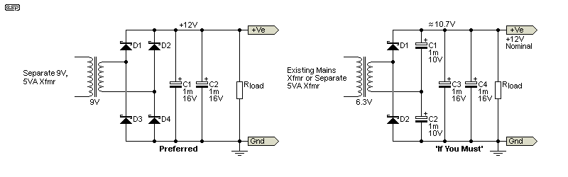
There are two supplies shown, the first using a 9V winding (or separate transformer), followed by a simple bridge rectifier, and the second is a voltage doubler. The first assumes a separate transformer, and the second requires that you have a spare 6.3V winding. The nominal DC voltage is ~12V for the bridge, and ~10V for the doubler. The voltage will vary as the amp is driven, and with mains fluctuations. Schottky diodes are used to minimise the diode losses, as they have a lower forward voltage than standard silicon diodes. If you use an extra transformer, use one with a 9V secondary and the bridge, as this provides ~12V DC which is more suitable for driving the relay. The transformer will need to be about 5VA. The output voltage will be somewhat 'soggy', but provided the 5V comparator supply remains fairly stable that doesn't matter. By using multiple 1mF caps you'll save money over using anything bigger, and 1mF 10/16V electros are only quite small so won't cause any space issues. Make sure that they are well separated from any heat source!
One could add a small switchmode AC-DC converter to get a 12V supply, but I'd expect that most valve amp owners wouldn't like that approach. There's no reason not to use an SMPS, just as there's no reason to use a valve rectifier (a truly horrid component that has only one redeeming feature - the HT is delayed because the rectifier valve's filament/ heater takes time to heat up). By default, it provides a 'soft start' function. However, the maximum capacitance that can be used with any valve rectifier is seriously limited, meaning that good DC filtering is much harder than it should be. Most modern designs use silicon rectifiers ... but I digress
Electronics enthusiasts know that SMPS aren't renowned for their reliability, but neither are valves - especially now when the quality and reliability are so much lower than they used to be in the 1960s and 70s. If the SMPS does fail, it simply means that the HT isn't supplied because the switching circuit (electromagnetic relay or 'solid-state' switch) can't operate. Yes, this disables the amp, but so do countless other parts of the circuit if they fail.
When the relay engages, the total supply voltage will fall to about 6.2V, but by using an 'efficiency circuit' the current can be reduced to about 25mA total. Because we have a low voltage but relatively high current, we need to use a lot of capacitance. 1mF (1,000μF), 10V caps are cheap and fairly small, but a higher value is better. We need at least 3mF for decent filtering, plus another 1mF for the efficiency circuit. As shown in the PSU circuits, I opted for 3 × 1mF caps (for the bridge rectifier), which shouldn't cost more than AU$1.00 each.
Many modern amps include some opamp circuitry, either with ±12V or ±15V, but these are usually pretty crude and they are often just zener-regulated. Most will be unable to supply relay coil current, but others will be alright. You need to look at the schematic for the amp you are working on to determine if you can use any existing power supply,
One tricky part is the reference voltage. Because we only have a very low voltage to start with, the reference is lower than I'd prefer, but it doesn't need to be super-accurate. Ideally, it won't be regulated because that would mean that mains voltage variations are not accounted for, leading to possible failure to operate if the mains voltage is low. However, this makes the design more difficult, so it is regulated by a zener diode. The detection threshold doesn't change with the mains voltage, but it's easily adjusted to accept a reasonable range. A 10-turn trimpot is recommended.
There's no super-simple way to create a lock-out function, because valve amps always power on in a 'fault' condition (no bias voltage). To circumvent this, I used a latch that allows a 'recovery' from the power-on condition, but prevents it from happening more than once. This requirement adds complexity, as you can see from Fig. 12. The cost is low, but the latch circuit takes up space that may be in short supply in some amplifiers.
A lock-out circuit is an alternative to the mains disconnection scheme described above. I've included it because it may be of interest to some constructors, and it shows what's needed to perform what seems at first to be a very simple problem. The issue? Every valve amp starts up with a fault condition at power-on. It (normally) doesn't cause a problem, because the valves can't pass any current until the cathodes are hot enough to emit electrons. However, it's this initial 'fault condition' that makes it difficult to implement a simple circuit that can ignore that initial 'fault', but turn off the amplifier if it happens again (i.e. a real fault).
Failure of the bias supply ensures that the B+ remains off, but there are many faults that will allow the bias to recover after B+ has been removed. This may cause the circuit to cycle off-on-off-on (etc.). The cycle-rate depends on the nature of the fault. One way to prevent this is to add a latch function, allowing the bias to rise to its normal voltage once. Should the bias fail and then return, that would set the latch, disabling the amp until it's power-cycled (turned off, wait for around 30 seconds, then back on). The circuit for this is shown above. Most of the circuit is unchanged, but there are 2 extra diodes, one resistor and a CMOS 4013 dual D-Type flip-flop. The flip-flop is triggered by a rising voltage on the 'Clk' (clock) pin. Holding 'Clk' high does not cause further action, nor does the latch do anything when the 'Clk' voltage falls back to zero.
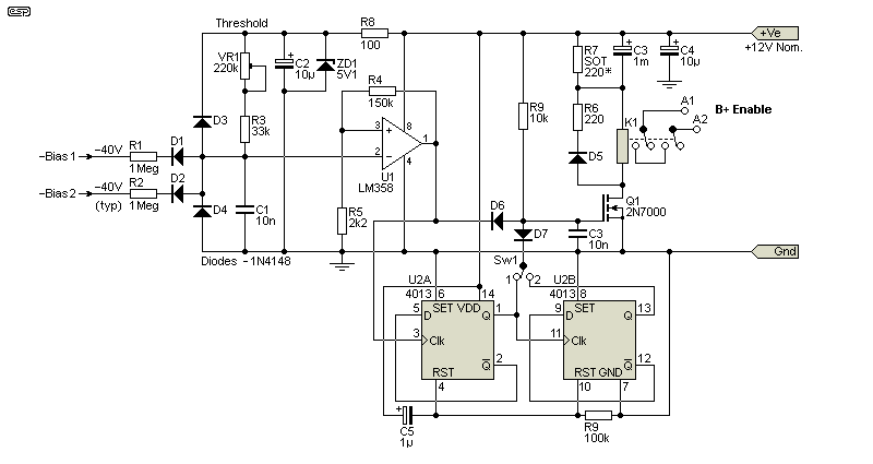
The function of the latch requires some explanation, as operation is not immediately apparent. At power-on, the latches (U2A and U2B) are reset by C5 and R9, forcing the 'Q' outputs low. When bias above the threshold is detected, the output of U1 goes high, and this sets the first latch so the 'Q' output is high. This causes the output of U2B to also go high. Q1 turns on, enabling the B+ supply. If anything causes the bias voltage to fall below the threshold, the output of U1 goes low and turns off Q1 via D5, switching off the B+ supply. There's no 'second chance' with the switch in position '1'. If position '1' is selected and bias voltage returns to normal because the fault has cleared (due to loss of B+), the output of U1 goes high, and this positive-going voltage triggers U2A, and its 'Q' output goes low, keeping the B+ turned off by removing the gate drive to Q1 via D7.
With switch position '2', if the first attempt restores B+ and the fault returns, the output of U1 goes high again, sending the Q output of U2A high, which toggles the second flip-flop (U2B) and its output goes low. This turns off Q1 via D7. B+ is therefore disabled permanently, until the whole circuit is power-cycled. D6, D7 and R8 form a simple AND gate, whose output (to the gate of Q1) can only be +12V if the outputs of both U1 and U2B are high. If either is low, Q1 gets no gate voltage and remains off, disabling the B+ supply.
Note that it's critical that the 12V supply be available to the comparator at least 500ms before the bias voltage reaches the threshold. With most of the simple arrangements you'll see, this isn't an issue, but (for example) the Fender version shown in Fig. 2 is fast - bias reaches -35V almost instantly. If your amp uses this arrangement (with no additional filtering), increase the value of the bias filter cap to around 220μF. This will not only give the required (small) delay, but the bias will be much smoother (less ripple) and will hold up longer when power is interrupted.
The circuit is deliberately designed to allow either no or one attempts at restoring normal operation. The second-chance allows for an accidentally disconnected mains lead, but once only. If there's a genuine fault that causes a loss of bias, the circuit will allow it to happen again, but only one time. The switch (Sw1) lets you set the 'fault tolerance' to either one attempt or no attempts to re-start (my default). If the switch is in position 1, one chance to power up the amp is all you get - if bias fails, the amp is locked out until it's power-cycled. The only reason the 'second-chance' is offered is because the second flip-flop is included in the package, and no extra parts are needed - other than the switch (which is optional).
Should a fault develop that reduces the bias voltage below the threshold (i.e. the voltage becomes less negative), the following sequence will occur after power-on ...
Call me paranoid if you will, but I would not be happy with the 'simple' version shown in Fig. 4 without a mains cut-off circuit. Many faults will not occur at all unless B+ is present, so a lock-out circuit is (IMO) essential. There are potentially a few issues that can cause bias voltage failure, but most can be prevented by a simple upgrade of the parts involved, i.e. dropper resistors or caps, making sure an open pot wiper is properly bridged as shown in Fig. 2 (Fender), and ensuring that the circuit is as robust as you can make it.
Although I haven't shown it, an LED (with current-limiting resistor) can be added in parallel with the relay coil(s). This will indicate normal function, and if the LED goes out during operation you know that the circuit has activated and there is a fault. Mostly this isn't really needed, as the lack of sound is something of a giveaway that all is not well. I leave this to the constructor.
In the following figures, I scaled the B+ and bias voltages so they would fit nicely into the graph. The actual voltages don't matter, and the only thing that's critical is the bias threshold voltage. In this case, it was set for 30V, with normal bias at -38V. This is not meant to represent any particular amplifier, it's simply an example so you can see the sequence of events.
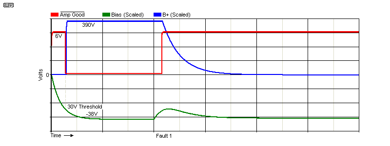
The single fault detection scheme is the safest, but it may be annoying in some cases. The waveforms are shown above. The B+ is inhibited until the bias voltage reaches the threshold of -30V, after which it turns on. At some point, a fault develops that reduces the bias below threshold, and B+ is turned off. The Amp Good signal (active low) is basically just the relay drive voltage, and when low it indicates that all is well and the amp can operate. When this goes high, the relay turns off and B+ is inhibited, so the fault cannot reappear. The fault could be a leaky G1 coupling capacitor, valve base or socket leakage, or someone turning the amp off then on again rapidly. It may also be due to the mains lead having an intermittent contact.
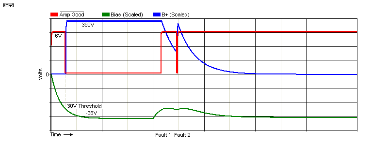
The restart may be the preferred option, and the waveforms are shown above. The basic operation is the same as for Fig. 13, except that the amp will restart (or attempt to) after the first fault. A second fault latches the system such that it turns off. The second fault may occur almost immediately, or it may be delayed by seconds, minutes or even hours. It could last a couple of seconds or several minutes, and during the fault B+ is removed from the main amp power supply. In both cases, a reset is performed by turning off the power, wait around 30 seconds, then turn it back on again.
Despite the apparent advantage of the latch circuit, my preference is to turn off the mains if a fault is detected.
The idea presented here is (to an extent) experimental. It has not been built, but it has been simulated using every possible way that bias may be compromised. It's up to the constructor to decide whether s/he needs a simple B+ removal (no latching), or the latched version set up for either one or two attempts at restoring normal operation. By including the switch, you can try both methods and decide which is right for you. Depending on the nature of the fault it may take seconds to hours between failures, but the circuit doesn't care - it will allow either one or two attempts to re-start, and will then shut down the amplifier.
The preferred method (IMO) is the mains disconnection version. While it needs three relays, it also provides the greatest protection. Because B+ cannot be applied until the bias voltage is normal, there's very little chance that any fault can cause further damage. Should the bias fail while the amp is in use (for any reason), B+ is removed, along with mains power.
The detection and lock-out functions can also be done using a microcontroller or PIC. That requires that a program be written and debugged, and while it simplifies the circuit, it remains a 'black box' with no way for anyone else to figure out how it works. Without access to the PIC and code, it can't be repaired if it fails. There's no change to the switching, and the power supply requirements are the same as shown. Any circuitry that lives inside a valve amp is at some risk due to the high voltages involved, and this circuit is no different. A misplaced test lead may be all that's needed to allow the 'magic smoke' to escape. With discrete ICs any damage is easily (and cheaply) fixed, but not so much so with a PIC. If enough people ask I will look into this in more detail, as there needs to be sufficient interest to make it worthwhile.
The circuit described is designed to protect output valves from severe overload if the bias voltage either fails or is compromised by valve base (or socket) leakage, internal valve failure, or any other fault that affects the negative bias voltage. As noted, some amps will blow the HT fuse (usually internal) if the amp is unplugged momentarily, or if someone just switches it off then on again within 2-5 seconds. While this may seem unlikely, consider that stage setup can be chaotic, and an IEC mains lead has a finite life. They are not intended to be plugged and unplugged constantly, as happens with amps that are set up and torn down several times a week (in some cases it may be a couple of times a day). The internal contacts fatigue, making the connection potentially unreliable. If the bias voltage collapses faster than the B+ voltage, a failure is almost guaranteed. Another cause for bias failure is a leaky grid capacitor, which injects a positive voltage that opposes the negative bias.
Valves are expensive, and adding a $20 circuit that can protect them against severe overload seems like it has to be worth the trouble of building the circuit and fitting it to your amplifier. Guitar amps are (generally) the most 'at risk', because the stage environment is frenetic at times, making accidents more likely. Random failures can occur with any circuit at any time, but if the detector fails, the most likely outcome will be that the amp refuses to turn on at all. The detector and relays require power to function, and about the only fault that could cause the circuit to malfunction would be an IC failure that makes the output of U1 high regardless of input voltages. This isn't a failure mode I've ever seen. However, it has to be mentioned because it's important to understand that nothing can be 100% reliable 100% of the time.
Likewise, I'm in no position to guarantee that the circuit can protect against all possible failure modes. Valves are complex mechanically, and can be affected by excessive heat (which can even cause the glass envelope to collapse), vibration, age and sometimes (or so it seems), whim. The common scenario I described earlier (unplug and re-plug the amp within a few seconds) is real, and is (probably) the one most likely to cause blown internal fuses and similar. Leakage (whether due to heat, spilled liquids, leaky grid capacitor(s), etc.) is less common, but nonetheless real. What you end up using depends on how highly you value your output valves and transformer, and also the likelihood (or otherwise) of bias failure for any reason.
Regardless of whether the amp is for home hi-fi or stage use, adding protection against bias failure is never a bad idea. The cost can be worked out easily, depending on where you are. If required, the additional transformer will be the most costly item, followed by the relays. The large caps (detector and power supply) are all low-voltage, and it will be cheaper to use all the same value of 1mF (1,000μF - simply parallel caps to get 3-5mF for the power supply). These shouldn't cost more than AU$1.00 each from major suppliers.
There are no specific references, other than to the bias supplies used in various Fender and Marshall (and other) amplifiers. The valve base pinouts are from manufacturer datasheets. The remainder of the circuitry is original content, parts of which may be used in other ESP projects.
The Valve Wizard (Bias) is a website article that covers the design of bias circuits rather well, and it's recommended reading.
 Main Index
Projects Index Main Index
Projects Index
|