
|
|
| Elliott Sound Products | Project 256 |
DI (Direct Injection/ Direct Input or just 'Direct') boxes are often a challenge, because there are conflicting requirements. Ideally, they will be phantom powered (P48V), but that means that they cannot have 'true' isolation from the mixing console. For P48V powering to work, the ground connection from the mixer is essential, but that kind of defeats the purpose of using an isolation transformer. Claims that active DIs 'colour' the sound are generally false - some might, but that would indicate a poor design.
This project does use a transformer, and it maintains reasonable isolation of the ground circuit by using a comparatively high-value resistor in the ground lead (XLR Pin 1). The audio is balanced, and also uses a comparatively high resistance from the transformer's centre-tap to obtain the operating voltage from the P48V provided on Pins 2 & 3. It is possible to use a battery, but this is always an issue for stage equipment. No one wants an instrument to suddenly disappear from the mix because the battery is discharged below the point where the circuitry can function. Using an AC mains powered plug-pack style external supply is also an option, but that just adds to stage clutter.
For most events, a battery will be replaced well before it's time, a waste of money and resources. However, this is an option with the design featured here. The constructor can decide whether to include a battery or not, depending on specific needs. Likewise an external DC supply can be used, although that's not something I really recommend. Small external switchmode supplies often create noise within the audio band if they aren't loaded to at least 25-50% of their maximum.
There is another way a DI box can be phantom powered with full isolation, but that involves using an ultra-low power switchmode supply supplied from the P48V, with the SMPS transformer providing the isolation and the supply voltage for the electronics. I have looked into this scheme (and tested it), and with so little current available from P48V, it's a bit of a challenge. The circuitry is simple enough, but the main problem I found was noise. The noise contribution was well outside the audio band and mostly inaudible, but it does cause some audible noise with very low levels. You can buy isolated DC-DC converters, but most have a no-load current that's far too high to be powered from P48V. The one I designed draws a miserly 1.4mA with no load! Overall, this method certainly works, but eliminating noise was too hard.
Passive DI boxes are fairly common, but they come with many limitations. Of these, input impedance is the 'killer', as it's simply not possible to get a high impedance without excessive attenuation. An output level of less than around 200mV means that the mixer input amplifier needs more gain, and that makes noise more of a problem. I elected to add a small amount of gain, so low-level inputs can take advantage of the 6dB of extra gain.
Unlike Project 35, this design uses a transformer to obtain the balanced output. Active balancing works, but it's never as good as a transformer. With the relatively high ground resistance, I was unable to induce a ground loop in my workshop. I tried everything I could, but eventually had to 'create' an artificial ground loop by injecting a signal into the ground circuit using a transformer. None of the interfering signal was present at the output of my mic preamp.
The audio transformer I used is a 10k:600Ω microphone type, and I've verified that it can handle up to 2V RMS at 40Hz without saturating. The impedance ratio is 16.7:1 (10k/ 600), so the voltage ratio is simply the square root of that, or 4:1 (close enough). The one I used is described in full below, but almost any mic transformer can be used. However, you must run tests to ensure that it will perform as expected.
Many people like passive DIs, but they come with serious limitations. The input impedance is way too low for most instruments (e.g. guitar or bass direct), so they have to be used with a preamp output if one is present on your amp. Because of the low input impedance, passive DIs can't be used directly with anything having an output impedance of more than a few hundred ohms. If one were built using the transformer I used, the input impedance is around 10k, but that also depends on the input impedance of the mixer. The source (instrument, preamp, etc.) needs to have the lowest practical output impedance, with an upper limit of around 100Ω. An active DI uses either an opamp or discrete circuitry to buffer the transformer, so the instrument isn't loaded by the comparatively low impedance of the transformer. Transformers (all transformers) work best with the lowest source impedance possible.
High impedance transformers are available, but expect to pay dearly for them. You can expect them to cost at least AU$180 or so. I can understand why they are so expensive, as they require thousands of turns of very fine wire and the best laminations you can get to obtain the required inductance - you need 800H for response to 30Hz with a 150k impedance transformer. That's not trivial!
By including a buffer stage, the transformer is driven from close to zero ohms (the opamp's output), with only a capacitor in between. The cap is needed to keep DC out of the transformer, as that will cause saturation, high distortion and a very low output level. At the lowest frequency of interest (typically 30Hz), the cap adds about 24Ω of capacitive reactance, so performance isn't compromised.
The standard phantom supply is +48V (P48), which is supplied to the signal lines via 6.81k resistors (the official standard). The resistor value is usually just 6.8k, but the tolerance should be better than 1%. This is so that common-mode balance is not affected, but you can select the resistors to be much closer with an ordinary digital multimeter. With 1% tolerance, the maximum CMRR (common-mode rejection ratio) is typically 60dB, but this can be reduced if one resistor is 1% high and the other 1% low.
The resistance limits the short-circuit current to about 14mA, but in most cases you'll want to keep the current drawn by phantom powered electronics to 8mA or less. A resistive feed is generally required at both 'ends' of a P48 powered system. There are the two 6.8k resistors at the mixing console, and another pair at the powered device (microphone, DI box, etc.). The 'remote' resistors don't have to be 6.8k, but can be any value that the designer feels is appropriate. A reasonable minimum is 1k, but they can be up to 6.8k.

A resistive feed is the most common now, and is (almost) the only option for an active balanced circuit. The centre-tapped transformer was popular when valve mic preamps were common, as the voltage boost means lower noise. A transformer lets you supply a higher current than you can with resistors, but the recommendation is that the feed current should be the same as provided by resistors. This indicates a 3.4k resistor, but 3.3k is close enough. Not all transformers are available with a centre-tap, so a resistive feed can be used to each transformer terminal. There are a couple of other alternatives, but they won't be covered here. The centre-tap causes the current in each half of the winding to be the same, and prevents core saturation from the DC component.
Resistor feed can be used with transformers just as it can with active balanced circuits. There is no 'official' value for the resistance used in P48 powered equipment and it can be as low as the circuit can drive. In general, anything less than a pair of 1k resistors is probably unwise, as the powered circuit must be able to drive both the power feed resistors and the mixer load. This is (or was) nominally 600Ω, but in reality it's usually around 2-5k.
However, it's sensible to allow for a 600Ω load, as this may be the impedance of some early mixers. It would be very uncommon (I've never seen a mixer with a 600Ω input impedance), but that doesn't mean it's impossible.
If the remote circuit includes a transformer with a centre tap, the resistance can be zero, but that can cause a ground loop via the DC smoothing cap which is always needed. The DC supply and 'ground' are as one for AC, so neither can be grounded or a ground loop can be created. I wouldn't recommend anything less than 100Ω, with a second 100Ω resistor in series with Pin-1 of the XLR to remote ground. This should be bypassed with a cap of between 10 and 100nF to suppress RF noise. I've chosen 270Ω as a reasonable compromise between voltage drop and isolation.
one thing that most people don't consider is cable capacitance when an XLR lead is connected to a mixer and P48V is turned on without the remote load (DI box etc.). The cable's capacitance might be around 500pF/ metre, so a 10m cable will have 5nF of capacitance. Without the load, this capacitance is charged to 48V. When the lead is plugged into something, the capacitance must discharge, and the current can be very high. There's not much energy (about 5.7μj), but the instantaneous peak current is limited only by the load's resistance. In the design shown here, the peak current is 109mA, limited by the two 220Ω resistors.
The most expensive part is the transformer. There are some 'open frame' transformers (mainly from Hammond) that are cheaper than the fully shielded type I used, but of course they are potentially susceptible to picking hum fields from nearby mains transformers. Cheap ones usually have a limited frequency range due to insufficient inductance, so you need to check the specifications carefully before you make a decision.
Any transformer that can't get below 150Hz or so is useless. These may be alright for telephone quality audio, but you use a DI box to get the best possible performance from a signal source. This is why you must double check the specifications, as they don't always provide all the information you need for a successful build. In fact, very few provide all the details you need to make an informed choice, regardless of price. I don't think that this is acceptable, but unfortunately it is what it is.
I don't have a Hammond transformer (e.g. 1140-LN-C at almost AU$140), but the one I used has the same ratio and is from a local supplier called Altronics. It's low-cost compared to most you'll come across, but it has very acceptable performance (tested and verified). Most of the details shown were measured, as the datasheet is sparse on the finer points. The transformer details are for the Altronics M0705, costing about AU$30.00 at the time of writing. Note that the Hammond transformer has one feature lacking on the one from Altronics - an inter-winding shield. This can help reduce noise that's capacitively coupled from one winding to the other.
Specification Value 10k:600 * 4.08:1 Primary R 456 Ω Inductance 41 H (1 kHz) Secondary R 27 Ω (13.5+13.5) Inductance 826 mH (1 kHz) Pri-Sec Cap. 39 pF Leakage Inductance (LL) 18 mH (Sec Shorted) 2V in 480 mV out (25 Hz-100 kHz)
* Note that the only specification for the transformer I used is the impedance ratio, which I have reversed (it's stated to be 600Ω to 10k). All other figures were measured. Leakage inductance may look high, but it's only a tiny fraction of the primary inductance. At 100Hz, the inductance measured 117H, with LL of 23mH. Inductance is frequency dependent because the internal losses increase with frequency.
Of course, not everyone wanting to build a DI box will be able to get the transformer shown, and while similar types are available, most are not inexpensive. Most decent transformers will cost at least AU$100 or so, with some costing a great deal more. In many cases, it will be easier to get 600:600Ω transformers, but most will have to be operated at no more than -10dBu (roughly 300mV) to get down to 30Hz without saturating. This is why you need to test any transformer you intend to use.
I used the mic transformer in reverse, so it operates as step down rather than its 'normal' role as step up. All transformers can be operated in reverse, and there is no difference either way - they perform as predicted by transformer theory in either direction. An alternative to the step down operation is a 1:1 transformer, which will typically be rated for 600:600Ω.
The minimum inductance is easily determined, using the standard formula for the expected -3dB frequency. Note that the inductance does not guarantee a saturation level, as this is determined by the maximum flux density that the core can support. This is dependent on the core material and the core size - a larger core can support higher magnetic flux for a given core material.
XL = 2π × f-3dB × L
L = XL / ( 2π × f-3dB
We always get better performance from a transformer if it's driven from a low impedance, and this can include negative impedance. While this does provide many benefits, it's impractical to add the extra circuitry because the transformer that you use cannot be determined in advance. See Negative Impedance and Audio Transformers.
Consequently, we will use 'conventional' voltage drive, with the transformer driven by as close to zero ohms as we can. The maximum input level you can use is determined by the transformer, and this can only be determined by testing. In most cases, the nominal peak level will be 0dBu (775mV RMS), but some transformers are designed for anything up to +4dBu (1.23V RMS).
Because transformer manufacturers don't always provide the info in a way that's useful, the following formulae will help you to convert voltage into dBu and vice versa.
dBu = 20 × log ( VRMS / 0.775 )
dBu = 20 × log ( 1.23 / 0.775 ) = +4dBu
VRMS = 10^( dBu / 20 ) × 0.775
VRMS = 10^( 4 / 20 ) × 0.775 = 1.23V
For dBV, simply omit the '0.775' term. For example, +4dBV is 1.58V RMS, with 0dBV being exactly 1V.
Occasionally you will come across transformers capable of as much as +24dBu (12V RMS). There is almost no input circuitry that can handle that level, and you may see it referred to a frequency of 50Hz or so, and at 1% distortion. Any amplifier stage to suit that voltage needs a minimum of a ±20V power supply, which exceeds the capabilities of most opamps. At lower levels you do get lower distortion at lower frequencies, so the capabilities aren't necessarily wasted (assuming you can afford the transformer of course).
The next choice is the buffer amplifier. While a simple discrete buffer may seem like a good idea, it will use more parts than an opamp but can never be as good. An option is shown below, but it will draw more current than most opamps, but with lower performance overall. The input must be protected against excessive voltages that will damage or destroy the transistor or opamp. This is provided by a 1k resistor and a pair of 5.6V zener diodes. Ideally, you'll use a 1W resistor for Rin so it doesn't burn out if the input is fed from a power amp. However, if the amp is sufficiently powerful and driven to maximum output, expect smoke from Rin!
Forget the BS you'll hear in some quarters about the alleged 'sound' of opamps, as it's mostly nonsense. Almost any competent opamp used as a unity gain buffer (or with a gain of two as used here) will be completely transparent, so the choice comes down to power drain and cost. The venerable RC4558 (much loved in pedals and guitar amps) is surprisingly good, low cost, and an has acceptable operating current. It will also function with a supply voltage as low as 4V, but this would needlessly limit the peak operating voltage. However, its input stage is not optimised for high impedances. While the LM358 may look like a good choice due to its very low current, it has high distortion and is not suited to audio circuits.
Phantom power has a limited supply current, with the maximum available across a short-circuit (14mA total). If we need a 12V supply for the electronics, the maximum current we can draw is 10mA, which is just enough to power most common opamps. A few examples are shown below ...
Device Current (Max) Typical Discrete 2.5 mA 2.5 mA TL071 2.5 mA 1.4 mA TL072 5 mA 2.8 mA NE5534 8 mA 4 mA OPA134 5 mA 4 mA RC4558 6 mA 6.7 mA Note 1 RC4580 6 mA 6 mA Note 1
1. The RC4558 and RC4580 are dual opamps.
There are many other opamps (including the venerable μA741, which is not recommended), but in most cases a lowly TL072 will do just fine. The opamp is used with a gain of two, so has close to the maximum possible feedback, and using something 'exotic' (and therefore expensive) isn't warranted. Many 'premium' opamps will draw too much current, including the NE5532, although some might be alright. The half-voltage supply (R2 and R3 in the drawings) may need to be adjusted if the opamp doesn't have a JFET input.
While it might seem possible to get 10mA for the electronics, this is harder than it seems at first. The P48 circuit uses a pair of 6.8k resistors (effectively in parallel) to supply current, but the DI box requires resistance too. With a centre-tapped transformer, that can be used to extract the voltage with almost no extra resistance. However, if you can't get a transformer with a centre-tapped winding, you have to use resistors. If too low in value, they will overload the drive circuit, so the minimum value you can use is around 1.5k (a series value of 3k). The drive circuit can handle that, and the extra resistance means that in reality we can draw a maximum of 8mA with an internal 12V supply.
A discrete circuit can be used, but it will never have the performance of an opamp. An example is shown next, and only one is required for the DI box. I elected not to use a JFET because the available range is greatly diminished these days, and the switching JFETs you can get tend to be rather noisy. Yes, I know that you can get 'audio grade' JFETs from some suppliers, but using a FET also means that the circuit needs a trimpot to adjust for a half-supply voltage at the output. If the output is offset you get asymmetrical clipping and reduced signal level.
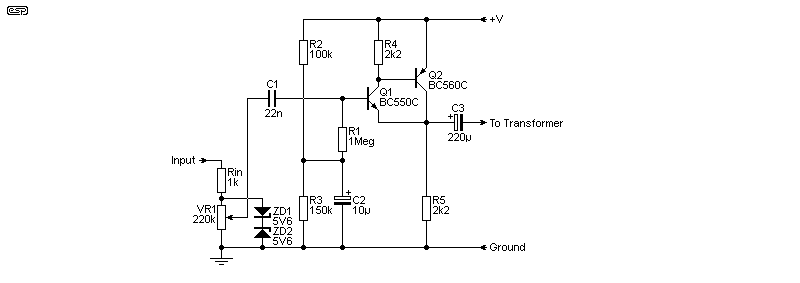
Figure 3 - Discrete Buffer
The circuit is basically an emitter-follower, but with much higher performance than a single transistor. You will see that it needs 2 transistors and 2 resistors, where an opamp follower needs no resistors at all (other than for the bias circuit, but that's the same for both). You'll be hard-pressed to get the 4 components to take up less PCB real estate than a dual opamp package! However, it will perform well, with an input impedance of just under 1MΩ and fairly low noise. The transistors used should have the highest hFE possible. The circuit has limited drive capability and draws almost as much current as a TL071, plus it's not possible to get any gain from it.
There are other options to create a buffer, but most will not perform as well as the one shown unless they are considerably more complex. The transistor arrangement is a Sziklai pair, which has both very high current gain and excellent linearity. However, I consider an opamp to be a far better alternative as it can drive much more current and has superior performance in all respects. As you'll see, I elected to use a dual opamp (TL072) so that the second opamp can drive a meter without adding any distortion to the transformer drive. The second opamp in the package (if used) is a unity gain buffer.
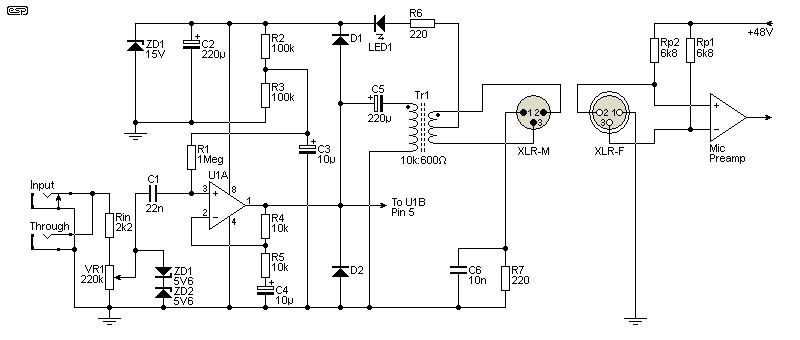
The circuit doesn't use an input buffer, so the level pot has to be a high value. Because the pot is at the input, the maximum input level is up to at least 10V RMS without any problems. With an input impedance of 220k (set by the pot), the impedance is high enough to be used with a guitar or bass. The isolation resistance is actually 135Ω because the two 270Ω resistors are effectively in parallel.
The worst case LED current ('active' lead plugged in) is about 100mA, so the LED must be a 'standard brightness' type. These are typically rated for about 130mA peak (100μs), and even with a 10m lead the peak current exceeds 40mA for only 2.5μs. It's generally understood that P48V should only be activated when everything is connected, but in reality we must expect that 'hot' leads will be plugged into equipment. Unless leads are very long indeed, the arrangement I used will be perfectly safe. The alternative is to use an LED in parallel with the supply (with a limiting resistor), but that uses some of our precious (very limited) current. For parallel use, a high-brightness LED is essential, limited to about 1mA.
With a 12V supply, the maximum input level before the opamp clips is at least 8V peak-peak (2.8V RMS). The maximum level you can use is about 2V RMS, but you can get more if the bass is limited to 40Hz. This will let you use up to 4V RMS, giving an output to the mixer of about 1V RMS (with the suggested transformer).
If you can't get a centre-tapped transformer, you have no choice but to use resistive feed. I've used the lowest practical value, and this has been tested and shown to work perfectly. It's not quite as good as the centre-tap, but the difference is academic. The main difference is the available supply voltage, which is reduced somewhat (opamp dependent). An option you can use if the supply is less than 10V is to use a TL062, which operates down to lower voltages. In my experience this isn't an issue with modern TL072 opamps, and I've verified that they will work with an 8V supply (despite the datasheet never having been updated).
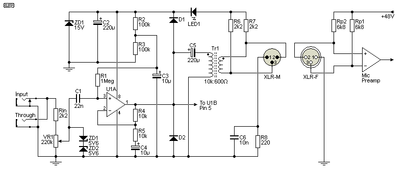
The isolation resistance of the Fig. 5 version is a little higher than for Fig. 4, at about 217Ω If you have (say) 5V of ground noise at 50/ 60Hz, the worse-case resistance only allows a loop current of 37mA. The loop voltage will normally be a couple of volts at the most, so there is no reason to expect that even fairly lowly transformers will not be up to the task. This may not be the case if one of the earth/ ground circuits has a lot of high-frequency noise, as created by traditional TRIAC dimmers with incandescent lamps. These are mostly a thing of the past now, but a decent transformer will still provide good attenuation of any ground noise. I ran a test with an effective 'ground' loop voltage of 7V RMS, and the hum output was buried in noise.
Because we know that the transformer has a limited input level, some constructors may want to add a VU meter (an alternative is a clipping detector). This is easily done with the second half of the TL072, operating as a buffer to ensure that the meter rectifier's noise doesn't create audible distortion. The Project 246 clipping indicator can also be used, with a few small modifications to reduce its operating current. Personally, I like the meter - it doesn't have to be especially accurate, but it will show if the level is too high. This addition is important if you're using the DI box for anything with a lot of bass - especially if it extends below 40Hz.
The diodes should be either Schottky (e.g. BAT46 or similar) or germanium to get the lowest threshold voltage. I used germanium diodes because they were on hand, and have been the default in most 'self-contained' VU meters. The meter I used is 500μA, and is close to perfect with no calibration needed. The meter can be allowed to peak (+5dB on the one I used) occasionally, but should always show an average of between -10 to 0dB. This is easily determined by eye.
A cheap 'VU' meter such as the one I used can be obtained for around AU$12 or so from eBay, or a bit more from Amazon. It must be capacitively coupled to the output of U1B, and well protected mechanically. Stage gear gets pretty harsh treatment, so you really need something that's close to indestructible. Note that some commercial VU meters may not be sensitive enough for the levels encountered and may load the output of the opamp. If you wish to use a meter, you'll need to work out the details based on the meter you have (or can get).
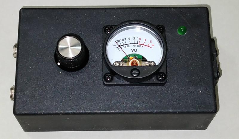
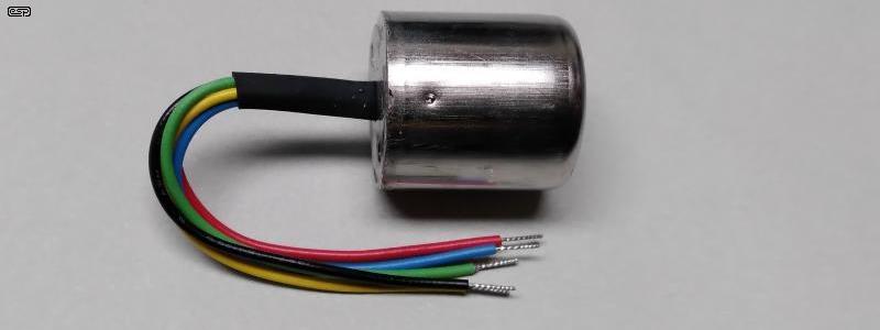
To give you an idea, the pic shows my prototype unit. The meter is illuminated by placing its LED in series with the green one on the front, but in reality the green LED is redundant. I didn't realise that the meter's internal LED would be quite so effective - indeed I didn't even know that it was an LED because the listing described it as 'incandescent'. As I discovered, that term was used to describe the colour temperature of the LED, not the actual light source.
We're not silly enough to build a valve-based DI box. Of course it can be done, and it wouldn't be especially difficult, but not with phantom power. A mains supply would be essential, and that adds considerable cost and size. It needs to provide 6.3V (or 12.6V) for the heaters (at up to an amp or more depending on the valves used) as well as a high-voltage supply of not less than 100V.
There are no sensible reasons to use a valve circuit, and while some people may assume it will somehow sound 'better', this is generally not at all true. The idea of a DI is that it should be as 'transparent' as possible, but a valve circuit will add colouration (especially distortion) that may make everything connected to the DI coloured, so it's not direct at all. Effects are added by the musician and/ or the engineer on the mixer as needed, not added by default to any signal that's sent to the console by a DI box.
This has been done (of course it has!), but even if you were to use the lowest possible heater current device I know of (the Korg 'Nanotube' 6P1) it's a stretch. The typical filament current is 17mA which is already outside our P48V limit of 14mA (short-circuit). Nuvistors (e.g. 8393 or similar from RCA) are completely out with a heater current of 60mA at 13.5V. There might be something suitable, but nothing I'm familiar with is suitable.
As noted in the intro, there are DI boxes that use a DC-DC converter to provide full galvanic isolation of the phantom power and a transformer to isolate the audio. They aren't common though, and as you'd expect they will typically be fairly costly. While it may seem that this would be essential, doing so adds extra cost and complexity to the circuit, but without any significant gain. There are plenty of circuits on-line that use a 'ground lift' feature, but they always leave an impedance between the signal input ground and Pin 1 of the XLR.
Designing a SMPS with extremely low current drain is a challenge, and it's something I have experimented with. I have built and tested a suitable candidate, and it worked perfectly. One issue I was not able to solve was high-frequency noise, that was sufficient to completely obscure a 2mV signal. However, it's not audible unless the mic preamp is set for maximum gain, where the noise is sufficient to cause preamp overload. However, it could be useful for other applications.
The DI box described here has been built and tested, and it performs very well. The only departure from 'transparent' sound is due to the transformer, especially if it's driven hard at low frequencies. This is the case with all transformer-based DI boxes, because all transformers have a limit to the level they can handle at low frequencies. Higher frequencies (e.g. 200Hz and above) aren't a problem, and most signal transformers can handle prodigious input levels at frequencies that are high enough. Core saturation limits the minimum frequency for a given signal amplitude.
The 135Ω isolation provided by the design described can withstand several volts of AC 'offset' (created by imperfect grounds and/ or ground loops), with hum rejection being entirely dependent on the audio transformer. As with any transformer-based DI, it must be kept well away from mains transformers in other gear. For example, it would not be a good idea to sit the unit on top of a guitar or bass amplifier.
There are no references as the basic circuit uses completely conventional circuits throughout. Most of the ideas used are already published on the ESP website.
For those unfamiliar. I have included a link to info about Nuvistors ...thevalvepage.com - /Nuvistor
 Main Index
Projects Index Main Index
Projects Index
|