
|
| Elliott Sound Products | Project 178 |
It's tempting to imagine that if you need a small power amp, there should be an IC made just for the job. Unfortunately, this is usually not the case. There used to be a great number of such amp chips, but over the years most have been dropped from production and are no longer available. The majority of the 'automotive' amplifier ICs use quite clever designs to get the maximum power available from a single 12V supply. The number of devices currently available has fallen dramatically, and the one suggested here is one of the few remaining that meets requirements and can still be obtained from mainstream suppliers. There are a few other likely candidates if you feel that you can trust certain Asian sellers, and while you may be lucky, it's not something you can count on.
A discrete solution can be made up easily enough, but the cost of the parts will generally far exceed that of an IC, and discrete circuits require a great deal more PCB real estate. Yes, SMD parts can be used to keep the size down, but they are tiny, easily lost, difficult to solder to a PCB, and usually only available in fairly large quantities. Also, consider that the maximum you can get from a single amplifier with a 12V supply is 2.25W into 8 ohms ... assuming zero losses. In reality, the final figure will be closer to 1 - 1.5W. Because the amplifier's output will be sitting at ~6V (½ supply), you need a substantial electrolytic capacitor at the amp's output to prevent DC from flowing through the speaker's voicecoil.
Where we used to have a great many ICs to choose from, the 'sensible' choices are now reduced to just one or two. There are more, but they are either SMD or Class-D, or are stupidly expensive because they are being supplied to repair existing equipment. To this end, I finally decided on the TDA7297, because it's a reasonable price, is still readily available, and requires the absolute minimum of support components. It's a dual channel IC, so you get a stereo amplifier. If you only need mono, just ignore one of the amps completely. This may seem a bit silly, but it's cheaper than using a dedicated mono amplifier because they are so hard to find.
Of course, you can just use an LM386 or its higher powered cousin, the LM380/384. Unfortunately, these ICs don't qualify as anything beyond 'utility', having relatively high distortion and very low output power. Expect no more than 1.5W into 8 ohms (at 10% total harmonic distortion + noise (THD!) with a 12V supply for the LM380 ... with heatsinks. This is pretty woeful, and Project 160 discusses these devices in some detail. They are useful for the basic tasks described in that project article, but for anything even remotely 'serious' they simply don't cut it. Because they use a simple DIP (dual inline pin) package, attaching a useful heatsink is not easy.
The 'suggested design' in this project is a simplified version of that shown in Project 169, which is a somewhat tongue-in-cheek dig at a piece of audiophoolery that a reader pointed out a couple of years ago (at the time of writing). Some people will go to extraordinary lengths to try to separate the gullible consumer from his/her money.
It's useful to look at the requirements for a basic single supply amplifier. Both input(s) and output(s) must normally be capacitively coupled, because the circuitry uses a ½ supply reference (may be internal or external). This allows the output to swing positive and negative with respect to the reference. If we assume that the the output can swing to the supply voltage and ground (none can do so), for a single 12V supply, the peak-to-peak output is 12V, which is 6V peak or 4.24V RMS. In an ideal system (which exists only in theory), the maximum power available is 2.25W into 8 ohms, but very few ICs can manage more than around 1.5W due to internal losses.
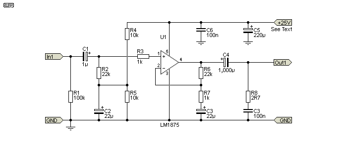
The circuit shown below is indicative of what you'd need for a single-ended IC power amplifier operating from 12V. The device specified is pretty much the 'last man standing' in this area, but it won't work at all well (if at all) with a single 12V supply. It's used in Project 72, but with supply voltage of around ±20V. These ICs work very well with the suggested voltage (and/or dual supplies), but this isn't always easy to provide in a project that doesn't otherwise use the higher voltage and/ or dual supply rails.

Figure 1 - General Scheme For A Single Supply Amplifier
There are rather more parts than many people would like, especially for a simple application. This is another reason that people use the LM386 (and its relatives) - very few support parts are needed. Trying to use an LM1875 (even if it did work properly with a single 12V supply) means far more parts than strictly necessary. All single-ended, single-supply power amplifiers have one major drawback - the cost and size of the output capacitor. Just to get acceptable response at 40Hz means a 470µF cap, rising to 1,000µF for 4 ohms. Normally I'd recommend at least 2,200µF to get worthwhile bass performance with minimal distortion. The cap has to be able to withstand the speaker current without getting stressed, and that can mean a larger capacitor than expected.
Although most of the TDA series of IC power amps have now been discontinued, you may still be able to get them. These range from the TDA2002/3/5/6 up to the TDA2050, an almost exact replacement for the LM1875. You will find listings on ebay, with the suppliers being from China. It appears that the IC is still produced there, and while most carry the ST (SGS Thomson) logo, it's probable that they are not the genuine article. It's not known if these Chinese versions work properly or not.
Many of these single-chip power amp datasheets don't say the minimum supply voltage that will work, but I found experimentally that the TDA2050 manages to operate with a total supply voltage of under 10V. Power output is very low as expected - with a 10V supply it's just over 1W with an 8 ohm load. If you have an unregulated supply of 20V or so, Figure 1 (using whichever IC you can get hold of easily) will deliver at least 5W, and these ICs have very good fidelity (THD is typically less than 0.05%).
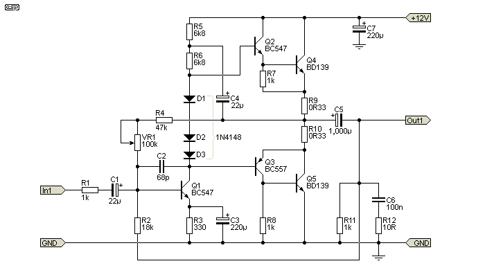
A discrete design is certainly feasible, but to get acceptable performance it will be fairly complex. About the simplest possible will still require 5 transistors, 10 or so resistors, and at least 5 capacitors. This will allow perhaps 1.4W into 8 ohms at 1% distortion. While it might be a bit of fun to build (and as such a schematic is shown), it's hardly an economical solution. In particular, the output capacitor needs to be no less than 1,000µF for 8 ohms, because of the way feedback is organised (it's taken from after the output cap). The input impedance is low too - only about 1k with the values given. Increasing the value of R1 increases input impedance, but reduces gain. With R1 = 1k, sensitivity is about 212mV RMS for full output, a gain of 15 (a little under 24dB).

Figure 2 - Discrete Single Supply Amplifier
This is pretty much the way most direct-coupled amplifiers were designed in the early days of transistor circuits. Even earlier (not direct coupled) versions used transformer coupling, transformer outputs or Class-A inductor-loaded output stages, but they are not considered because of the difficulty of obtaining cheap but usable transformers/ inductors. Even if found, they will be large and anything affordable is unlikely to perform well. Inductor-loaded Class-A is out of the question because of high quiescent current (a minimum of 1A for an 8 ohm load) and higher than acceptable distortion.
The circuit shown can be surprisingly good, but the low power and relatively high component count mean that it's completely impractical these days. The trimpot (VR1) is adjusted to obtain +6V at the positive terminal of the output capacitor (C5). It's possible that R4 may need to be changed, depending on transistor characteristics. The parts shown are sufficient for an amp running from 12V and an 8 ohm speaker. Increasing the voltage is not recommended, although you could use up to 16V or so at a pinch. Do not use less than an 8 ohm load though. The output transistors (Q4, Q5) must be mounted on a heatsink. Power supply hum rejection should be adequate, providing that the supply is reasonably free of ripple.
Other alternatives exist, such as using an opamp with current booster transistors, but the internal losses are too high, limiting the output power to about what you'd expect from an LM386. The end result is more complex and considerably more expensive than an LM386, but it can provide very high quality. This is the approach taken in the Project 113 headphone amplifier, where it's ideally suited. While it can drive a speaker, it's not recommended.
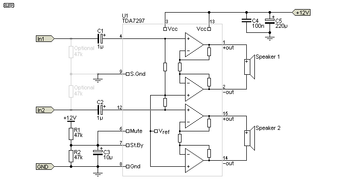
The alternative (and most suitable) design is shown below. The TDA7297 (or its smaller cousin, the TDA7266) is intended for TV and portable system use, and it will drive 8 ohm speakers to 5W from a 12V supply, with distortion below 0.1% at 1kHz (up to 15W is available, but with a great deal more distortion). Note that a heatsink for U1 is absolutely essential, even for testing. Most of the time, the chassis can be used as a heatsink, provided it's made from aluminium and no less than 2mm thick. 5W is hardly a powerhouse, but remember the purpose - provide a small power amp with reasonable performance for the lowest possible cost. The TDA7266 is rated for a maximum output of 7W. The schematic is adapted directly from the datasheet.
As with any power amplifier IC, supply bypassing is very important. I've shown a single 220µF bypass cap (C5), but a better solution is to use two 220µF caps, with one at each end of the IC so they are both close to the supply pins (3 and 13). It's not mentioned in the datasheet, but I strongly recommend that you use a 'bulk' electrolytic cap at the DC input. It should ideally be no less than 1,000µF. No input biasing resistors are needed, as the input pins are internally biased to ½ supply by the Vref internal reference voltage. If the inputs are connected via RCA sockets or some other connector, 100k resistors should be used, as shown in grey as 'optional'. This will prevent a loud 'bang' when the source is connected, caused by the input caps charging.

Figure 3 - Two Channel TDA7297 Power Amp
The amp is designed in such a way that it doesn't need many external parts. Unlike the majority of designs, no Zobel network (aka 'Boucherot cell') is needed at the speaker outputs, and there are no bootstrap capacitors that are common with some other power amps. Of course, this is a moot point, because most are now obsolete anyway. The amp is capable of up to 15W/ channel into 4 ohm loads, but distortion will be somewhat higher than you might hope for. My suggestion is to use a nominal 8 ohm load, and expect no more than 5 to 6W. While it doesn't sound like much power, it's actually more than sufficient for most projects where a simple audio power amp is needed. It's a great deal more power than you can get from the DIP packages, and performance is far better.
The gain is fixed at 32dB (×40, typical, ±1dB), and there is no option to change it. Input impedance is typically 25k, and if you don't need response below 30Hz the two input caps (C1, C2) can be reduced to 220nF polyester (e.g. MKT or similar case). Don't use multilayer ceramics for the inputs - these are suggested on some other sites, but they are unsuitable for audio coupling. If you only need one channel, the unused input should be grounded via the capacitor - do not connect the input pin directly to earth as the effects are unpredictable and it may damage the IC. Unused speaker outputs are simply left disconnected.
Although it's not stated in any of the data sheets I've seen, the heatsink tab is connected to Pin 8 (earth/ ground), so may be connected directly to the chassis. Be aware that doing so might create an internal earth loop that may lead to audible hum. It's often preferable to isolate the tab from the chassis with a Sil-Pad or a (greased) mica washer, but both will increase the thermal resistance. A separate floating (not earthed) heatsink can also be used. Pins 8 and 9 are not joined internally, and both must be connected to the earth/ ground rail for normal operation.
No-one will ever claim that this is a 'high performance' or 'high fidelity' amplifier, and that's not the intention. However, it offers an order of magnitude of performance improvement over the more common low power amps (LM386, LM380, etc.). It has more power, uses no more parts and you get two channels. The downside is that a heatsink is required, but that's to be expected of any amp that claims to be able to provide more than a few 10s of milliwatts. The amp sounds pretty good (at least using my workshop speaker and FM tuner), and with a speaker of average sensitivity it should be quite loud enough for normal home or workshop use.
Adding a heatsink is easy, because there's a large exposed metal mounting surface. The heatsink doesn't need to be particularly large, but I'd recommend nothing smaller than 10°C/W, and preferably 5°C/W if both channels are used to maximum power. This becomes more important as the supply voltage is increased, I suggest that you don't exceed ~16V (the absolute maximum supply voltage is 20V). As I have pointed out on numerous occasions, there is no such thing as a heatsink that's too big, so if you have something you can use that exceeds the minimum requirements, then that will be fine.
This is a very simple amp to assemble, with the only real down side being the package itself. Because of the pin spacings, conventional Veroboard assembly won't work. However, because there are so few external parts most people will be able to work out a suitable layout that shouldn't be too challenging. As noted above, there is simply no comparison between the TDA7297 and the more common single supply ICs. It has a great deal more power, lower distortion, and it's actually intended to be a 'real' power amplifier. This is in contrast with the LM386 and its ilk, which can really only be classified as an 'afterthought'. That's as in "Oh, bugger! I forgot to include an amplifier for the piss-ant little speaker in the case." Ok, I readily accept that it's still useful, but it's most certainly not a 'class act'.
The datasheet says that the TDA7297 was designed specifically for TV sets and portable radios. The standby and mute functions can be controlled by a microprocessor, but have not been implemented in the design shown. If this is needed, the datasheet shows the suggested interface networks that ensure click-free operation.
TDA7297 Datasheet
There are no other references, because the techniques shown are quite common, and the data presented were the results of simulations and workbench experiments to verify results.
 Main Index
 Projects Index