
|
| Elliott Sound Products | Project 160 |
Every so often, you'll find a need for a low power amplifier. It usually won't need to be anything special, but it will usually have to be cheap and easy to build. Uses range from signal tracers, workshop monitor amps (to listen to distortion residuals for example), or just a simple project for the fun of it. The National Semiconductor LM386, LM380 and LM384 ICs have been with us for a long time, and are well suited to simple projects that can be up and running in an afternoon.
None are anything special, and they are fairly low power (the LM386 is only rated for 300mW into 8 ohms). Distortion is acceptable at around 0.2% (at 125mW for the LM386, or at 2W for the LM380). These are certainly not hi-fi by any stretch of the imagination, but they are fine for a utility amplifier where a bit of distortion is unlikely to be a deal-breaker. The LM384 can (allegedly) provide up to 5W, but don't count on it.
There's no doubt that a small amp with similar performance can be made using an opamp and a couple of transistors, but the total cost and component count will be a great deal higher than will be the case with one of these ICs. There is (of course) a down side, and that's the heatsink needed for the LM380/384. They can be run without a heatsink, but only for low power output, and care is needed to ensure the IC doesn't overheat. The LM380/384 have over-temperature shutdown, but don't rely on it.
Of the three types, the LM386 is the more popular. While you may see it rated for up to 1W output, this is a little adventurous (to put it mildly). It's theoretically possible if you use a high supply voltage and a 16 or 32 ohm load, but that's not recommended because device dissipation will be well in excess of that which the device can handle safely. The load impedance needed is higher than any small speakers you can get, and you simply don't build an amp using an LM386 if you need more than a few milliwatts. Maximum output power into an 8 ohm load is around 250mW for acceptable distortion.
The IC is useful for headphones, intercoms, portable radios (etc.), and can also be used as a line driver because the output can handle a low impedance. However, the performance is such that I doubt it would meet the required standards for professional use, and I have never seen an LM386 used in pro gear.

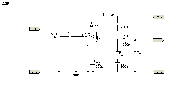
Figure 1 - LM386 Amplifier Schematic
The circuit shown is only partially optimised for best performance. The value of the output coupling capacitor determines the low frequency response, and 220µF is the minimum I'd recommend for an 8 ohm load. That gives a low frequency -3dB frequency of 90Hz, but you can use a cap of 1,000µF if you wish (-3dB at 20Hz). I don't think I even need to say that this IC isn't suitable for a subwoofer. 
The impedance at both inputs is 50k, set by internal resistors. The input capacitor is optional - you can connect the source (or pot wiper) directly to the input pin if you prefer. If you do omit C1, you will almost certainly hear some 'scratching' noises from the pot as it's rotated because there's a small DC offset at the inputs. The bypass cap (C2) is optional as well, but if you don't include it the power supply rejection is rather poor, so anything other than a battery supply may cause some hum.
You can use either input for the signal, and simply ground the unused input. Predictably, the +ve input is non-inverting and the -ve input is inverting. It's important to understand that the LM386 is not an opamp, and none of the traditional opamp circuits can be applied. The quiescent output voltage is set internally to be half the supply voltage, and by default the gain is 20 (26dB). The gain can be changed by adding a capacitor between pins 1 and 8. If these pins are linked by a 10uF capacitor, the gain is 200 (46dB). Add a resistor and capacitor in series between pins 1 and 8 for intermediate gains.
The Zobel network at the output is needed to ensure stability when leads are attached, but even if the speaker is only a few millimetres away, don't leave it out or the amp may oscillate. C5 is a supply bypass cap, and it should be as close to the supply pins as possible.
The LM380 is available in two packages - 8-pin and 14-pin. The 8-pin version is only suitable for low power (similar to the LM386), but the 14-pin version can be fitted with small heatsink 'flags' that allow it to provide up to 2.5W. Despite the fact that many of its functions appear to be almost identical to the LM386, the two are quite different and even the 8-pin versions of each have different pinouts and are not interchangeable.
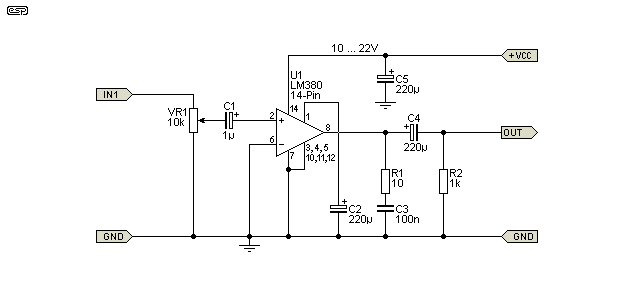
The 8-pin version is shown first. While it looks very similar to the LM386 circuit shown above, note that the pin numbers are different. I've shown the LM380 with the same component values as the LM386, and performance will be similar, but you can get higher power. The 8-pin version of the LM380 is capable of around 1W, but that's under ideal conditions. The supply voltage needs to be no more than 12V and the load impedance should not be less than 8 ohms.

Figure 2 - LM380 (8-Pin) Amplifier Schematic
The LM380 has a fixed gain of 50 (34dB) and unlike the LM386 there is no facility to change it. That means that the maximum input voltage will be around 100mV (RMS sinewave) at the onset of clipping. However, that varies with supply voltage and load impedance so you'll need to assess the circuit under your operating conditions.
The LM380 is also available in a 14-pin package, which has greater dissipation and can provide more power. The LM384 is virtually identical to the LM380, but is rated for a higher supply voltage (up to 26V DC) and higher power. 5W is claimed, but that's at 10% distortion so expect around 4W at sensible distortion levels.

Figure 3 - LM380 (14-Pin) Amplifier Schematic
The 14-pin version of the LM380 uses pins 3, 4 & 5, plus pins 10, 11 & 12 for connection to a heatsink. It is possible to use a ground-plane on a PCB as a heatsink, but it's not very effective and you need a lot of area to get what is still a sub-standard heatsink. The preferred method is to make (or buy) copper heatsinks that can be soldered directly to the pins. Note that you cannot use aluminium because it can't be soldered, but you may be able to use small copper tabs that are rivetted to an aluminium heatsink (with heatsink compound between the two metals).
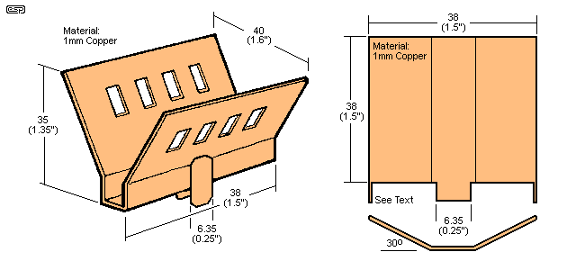
The suggested heatsink designs are shown below.

Figure 4 - LM380 (14-Pin) Heatsink Details
The heatsink on the left is a commercial design (which may be difficult to get), made by 'Staver' and is suggested for the LM384 - a higher voltage version of the LM380. The tabs solder to the IC pins, and the underside of the heatsink should be coated with heatsink compound to increase the thermal conductivity.
The heatsink on the right can be fabricated from sheet copper, and I added two 'spigots' that can be inserted into the PCB to stabilise the heatsink against vibration. Two are needed, one for each side of the IC. These are (allegedly) available, but I couldn't find anything even remotely similar from my normal suppliers. It should be easy enough to fabricate a suitable heatsink if you have some sheet copper available. It would be worthwhile to give it a very light spray with matte black paint to improve radiation.
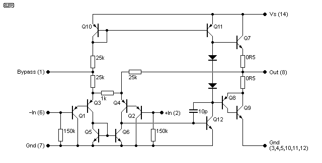
The internal circuit of the LM380/ 384 is shown below for reference. The LM386 is similar, but uses 50k resistors at the inputs, and has two series resistors (150 ohms and 1.35k) in place of the single 1k gain setting resistor seen below. All pin numbers refer to the 14-pin LM380 and the LM384.

Figure 5 - LM380/384 Internal Diagram
It's worth mentioning that the above circuit can be simulated and will give the expected results, but you need to replace the upper NPN output transistor (Q7) with a Darlington pair or you will not get symmetrical clipping. The circuit is shown for reference only, and is adapted from the datasheet (but has been redrawn).
Probably the most interesting thing to look at is the input stages. They are able to work with a signal that goes below zero volts (Gnd) because a PNP transistor is used. The negative input signal doesn't get cut off as you might expect, because the emitter is still positive. Input stage distortion will not occur until the input signal peak exceeds -500mV or so, and that's far more than necessary given the gain of the IC. That's one of the reasons that the higher voltage ICs (LM380 and LM384) have a higher gain than the LM386 - it's simply to ensure full output swing before the input stage causes distortion.
Construction of any of these amps is non-critical, and Veroboard or similar is the way that most people would build one. While a PCB would be handy, the cost of the board would be greater than the cost of the IC and other parts and it's not worthwhile.
The only thing that even approaches being critical is the bypass cap. The datasheets don't mention it, but there's every chance that the ICs will oscillate if you fail to bypass the supply. Feel free to include a 100nF multilayer ceramic bypass cap as close to the supply pins as possible (it's not shown in the above drawings).
If you want to extend the low frequency response, the output coupling capacitor will need to be increased from the 220µF shown. Using a 1,000µF cap will extend the low frequency response to 20Hz, but the speakers that will normally be used with these small amps won't go that low anyway.
If you expect to use the 14-pin LM380 or LM384 to provide more than 1W or so, you must provide a heatsink or the ICs will die. Those shown in Figure 4 will normally be acceptable, or you can fabricate something yourself that makes good thermal contact with pins 3, 4, 5 and 10, 11, 12. For best thermal performance, the heatsink(s) should be soldered directly to the pins, and ideally will also have a good thermal bond with the top of the IC package.
The power supply can be anything you have handy, including a battery. The minimum useful voltage is around 6V, and 12V is the maximum suggested for the LM386. LM380 or LM384 can use a supply voltage of 10V up to 22V or 26V respectively, but don't even think about it if you don't include heatsinks.
If you want to know more, have a look at the datasheets. These provide quite a bit of info, and lots of application circuits. These range from a Wien bridge oscillator to intercoms and various others.
 Main Index
 Projects Index