
|
|
| Elliott Sound Products | Project 166 |
 Main Index
Projects Index Main Index
Projects Index
|
Push-on, push-off switches are common in many products. In some cases the action is purely mechanical, with a special alternating latching mechanism that holds the switch in the 'on' position, and releases again next time the button is pressed. These switches used to be quite common, but were only ever available with a limited range of button styles. They are less common now, and it's likely that you won't be able to find a style or shape that suits your panel layout.
Momentary action switches are far more common, and come in a wide range of different styles. Some require only a gentle touch to operate, but of course they are not latching. This makes them unsuitable for switching on your equipment. You can use two switches, with one for 'on' and the other for 'off', but this is usually inconvenient and takes up more space on the front panel.
Electronic switching does have one down side, and that's the need for a continuous power supply. In some equipment that can be a problem, and of course a continuous supply means that some current is drawn from the mains all the time. If the supply is designed properly standby current will be very low, and the dissipated power can easily be under 1W with a suitable power supply.
This project will appeal to people who want to build an amplifier or preamp that has a 'modern' feel, using a single button to turn it on and off. As shown here, a mechanical switch is needed, so be aware that it is not a 'touch' switch. Most people won't be bothered by this though, since true touch switches seem to have fallen from favour.
The schematic of the first switching circuit is shown below. It uses a single 555 timer and a few passive components. The mains will usually be switched using a relay, either electromechanical or 'solid state', and driven from the output of the switching circuit. See below for more information on relay driving. C3 is not needed if the circuit is close to the power supply (less than 50mm or so). Otherwise, C3 is necessary to ensure that there are no supply 'glitches' when the output changes state. It should be located as close to the IC as possible.
Fig. 1 shows circuit of the switching system. When the pushbutton (Sw1) is operated, the output of the 555 timer will alternate between high (12V) and low (0V). The LED is used to indicate the state of the switch, and acts as a power-on indicator. C2 is much larger than is normally used with 555 timer circuits, and is used to force the 555 timer to a 'low' output voltage when power is first applied. This is the default and will be appropriate in most cases. If you prefer the 555 to output 12V when power is first applied, connect C2 between the 'Crtl' pin (pin 5) and the positive supply. The positive lead of C2 must go to +12V if wired this way.
R2 and R3 set the voltage on the 555's 'threshold' and 'trigger' pins to 1/2 the supply voltage - typically 6V. When the output is off (0V), the voltage across C1 will be close to zero, as it is discharged via R1. When Sw1 is closed (momentarily), the voltage at the threshold and trigger pins falls to zero for an instant, and causes the 555 timer's internal flip-flop to change state. The output goes high (12V), the external relay (or whatever is being controlled) turns on, and C1 now charges, reaching close to 12V in a couple of seconds.
The next time that Sw1 is pressed, the threshold and trigger inputs are forced to near +12V, causing the flip-flop to change state again. The output now falls to zero and the external relay turns off. Because of the rather long time constant of R1 and C1, switch contact bounce will not affect the circuit's operation, and spurious or random switching won't happen. If R1 or C1 are too low in value any contact bounce in Sw1 can easily leave the output in the wrong state, having gone high and low several times in a short period. The 1 second time constant used completely eliminates this problem.
For some examples of mains switching, see Project 156, which describes a number of circuits designed for 12V triggered mains switches. Provided you use a relay that doesn't draw too much coil current (most will be fine), you can simply use the output of the 555 to drive the relay directly. Be aware that you must never omit the diode across the coil, and you need a diode in series with the output of the 555 IC as well. This is because the 555 has an active output stage, but the IC's internal circuitry can 'latch-up' if even a small negative voltage is applied to the output pin. See The 555 Timer article for more information about the IC, its uses and limitations.
It's far better to use a transistor to switch the relay. This ensures that the output of the 555 isn't loaded excessively, as loading will cause a voltage drop at the output which may cause the circuit to be unreliable. For the sake of a few cents and the addition of one resistor and transistor, you can be certain that the 555 operates with the least possible external disturbance, and it will be free of any undesirable behaviour.
If you think that you'll need to operate the switch faster than once a second (very unlikely I would expect), you can reduce the value of C1. Less than 1µF is not recommended.
The second version [ 2 ] is rather more complex, but it has the advantage that only a single wire is needed to the switch and LED, plus ground, which will usually be the chassis. This reduces wiring, as the first version needs two wires for the switch plus another wire and ground for the LED. That's up to four wires in all, which may be a nuisance to connect. Naturally, any simplification of wiring is matched by more complex electronics.
This circuit uses some skulduggery to function, but it works well. Q1 is normally on, and the push-button turns it off when pressed. This forces the 'SET' pin of U1A high (U1.6) which overrides the 'RST' (reset) which is permanently applied by connecting it to the positive supply. This forces both 'Q' and 'QN' pins high, and the 'Q' output is used to toggle the state of U1B. If the 'Q' output (U1.13) is high, it's forced low (or vice versa). When the output is high, Q2 powers the relay and the LED (via D2 and R6). R6 is included to prevent the push-button from shorting the supply when Q2 is on.
Q1 turns on again as soon as the button is released, ready for the next button press. The 'skulduggery' is using U1A in an unconventional manner, essentially as a Schmitt trigger. Note that the relay and LED change state when the button is released, which may be a little disconcerting.
Whether you consider the extra complexity to be worth the effort just to save a bit of wiring is up to you. This circuit is more 'elegant', but there's little to separate it from the Figure 1 circuit from a usability perspective, and they will function equally well. Power consumption is negligible for both when off, and is mainly determined by the relay coil current when turned on.
There's also a discrete option [ 3 ]. While it will occupy much the same space on Veroboard as the Figure 1 circuit, it may be preferred by some constructors. It requires at least three wires to the front panel - two for the pushbutton, and one for the LED. This assumes that the common (ground) is available, but if that's kept separate from the main (chassis) ground you need four wires.
When power is applied, the switch is off, and C1 charges to the +12V supply. Pressing the button turns on Q2, pulling the relay to ground, and turning on Q1. C1 is then discharged to (close to) zero volts via R2. The next time the button is pressed, the gate of Q2 is connected to the now discharged C1, turning of Q2, which turns off the relay and also turns off Q1. C1 then charges to the supply voltage in readiness for the next button-press.
The time-constant of C1 and R2 is such that the switch is 'de-bounced', preventing spurious switching (push-button switches always show some contact bounce which can cause erratic switching if no precautions are taken. The type numbers for Q1 and Q2 are not critical, and almost anything you have to hand will work. Small-signal types are preferred. ZD1 protects the gate of Q2 from any stray transient voltages that may cause failure (I recommend using a zener with any MOSFET that doesn't have an internal gate protection zener). R6 is optional, and lets you verify operation without RL1 connected.
The next circuit was found [ 4 ] well after this page was put together. It's about as simple as you can get, but it works well. It seems to have no bad habits, although you may need to increase the value of C1 and C2. C1 is intended to prevent the circuit from powering 'on' when the 12V supply is connected. C2 determines the period between 'on' and 'off' cycles. It can be as high as 10μF, but you'll have to wait longer before you can turn the powered device 'off' after turning it 'on' (and vice versa).

The circuit can be used to power 12V circuitry directly (without the relay), but such circuits will almost always have a local capacitor. If (when) that is the case, the Schottky Diode (D2) must be included, or the circuit cannot be turned off. Q1 always requires a load, and the combination of the LED and R4 will not be sufficient due to the drop across the LED. In this case, include R5 which ensures there's enough load to allow the circuit to turn off. The maximum suggested voltage is 12V, as anything more may damage the MOSFET gates (most are limited to ~20V absolute maximum). Note that I have not included zener diodes to protect the gates in this version, so care against static discharge is necessary when wiring and soldering the circuit.
When the circuit is in standby, C2 is charged to (close to) 12V. Pressing the button connects C2 to the gate of Q2, turning it on. In turn, Q1 turns on, and provides gate voltage to Q2 via R3. C2 discharges to zero via R2, so the next time the button is pressed, it forces the gate of Q2 to zero, turning it off. When Q1 is off, there's no gate voltage for Q2, so it remains off. C2 then charges up to 12V again, ready for the next button-press (which will turn the output on again). Although I've shown Q2 as an IRF9540 P-Channel MOSFET, if your circuit draws minimal current it can be a much smaller MOSFET. Something like a BS250P (small-signal) will be fine for operating a relay, or for an output current of up to 100mA or so.
If you are not experienced with mains wiring, do not attempt the following circuit. In some countries it may be unlawful to work on mains powered equipment unless you are qualified to do so. Be aware that if someone is killed or injured as a result of faulty work you may have done, you may be held legally responsible, so make sure you understand the following ...

| WARNING : The following description is for circuitry, some of which is not isolated from the mains. Extreme care is required to ensure that the final installation will be safe under all foreseeable circumstances (however unlikely they may seem). The mains and low voltage sections must be fully isolated from each other, observing required creepage and clearance distances. All mains circuitry operates at the full mains potential, and must be insulated accordingly. Do not work on the power supply while power is applied, as death or serious injury may result. |
|
The drawing below shows a simple example of a mains switch, including the IEC colour coded wiring. This maintains isolation between the 12V supply and mains, so everything connected to the 12V supply can be handled safely. The power supply for the circuit can be a small transformer, rectifier and filter, or you can use the insides of an isolated switchmode plug-pack (aka 'wall wart') supply. There are many possibilities (including the one shown below), and you can have a look at the ESP article 'Small, Low Current Power Supplies' to see some other examples. The supply does not need to be regulated, but it should be reasonably free of ripple which again might cause unreliable operation.
If the switch is insulated to mains standards you can use a transformerless supply, but I never recommend them because they are inherently deadly. A transformer or switchmode supply is safe under most possible conditions, and failure between mains and low voltage circuitry is very rare. Provided the equipment is wired with a protective (safety) earth/ ground, even if there is a major failure, the users are still protected because the house mains safety switch will activate or the fuse will blow.
A suitable power supply is shown below. It's nothing fancy, and uses a small 9V transformer, four diodes and a capacitor. This is virtually identical to the supply shown for several other small ESP projects, and will provide close enough to 12V DC output. When loaded with a typical 12V relay (having a coil resistance of around 270 ohms), the ripple voltage will be about 50mV RMS. You can use a small bridge rectifier IC or module, but I expect most hobbyists will have a stash of 1N4004 diodes already.
There's nothing fancy about it, but if you use a transformer from an established supplier it will be safe and will usually last for the life of the equipment. The fuse is optional but recommended, and if possible choose a transformer with a built-in thermal fuse. An external fuse will typically be permanently wired (and insulated), since if it fails it probably means that your transformer has died. You can also use a switchmode supply (the innards of a plug-pack/ wall-wart for example) which will have a regulated output, but almost certainly won't last as long as the simple linear version shown.
Make sure that all mains wiring uses mains rated cable, and that joints are mechanically secure prior to soldering, and insulated against accidental contact. If you are unsure about your ability to perform mains wiring safely and to the standards required in your country, then get someone to do it for you. Take careful notice of the warning above - it's extremely important!
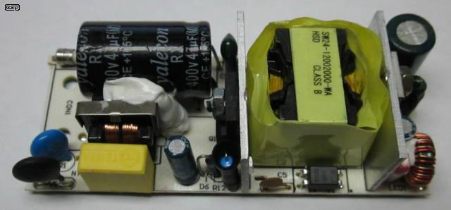
Some people may prefer to use a small switchmode supply, such as that shown above. These are fairly small, at 83 × 34 × 24mm (L×W×H), so will probably take up less space than a small transformer, rectifier and filter cap. There are many alternatives that also provide proper safety isolation and include mains input filtering. These are a safe and practical alternative to the conventional approach. For example, you can use the PCB taken from a commercially available (and genuinely approved - many Chinese 'approvals' are fake) wall supply (aka plug-pack, wall-wart, etc.), which should have safety approvals for the countries where it's sold. Most wall supplies will also comply with minimum energy performance standards (MEPS) if they apply where you live. Be very careful with these, as many are not fit for sale - see Dangerous Or Safe? - Plug-Packs (aka 'Wall Warts') Examined.
If you use a switchmode supply of any type, it will ideally be inside an earthed metal enclosure to minimise electrical noise and to keep it safe from accidental contact. Make sure that the supply is securely mounted with adequate insulation rated for mains voltage to prevent any short circuit to the case. Where the SMPS lacks EMI suppression components (such as many of the ultra miniature versions you may find), it's recommended that they be added or electrical noise may cause interference to other equipment.
Note that there are other, much smaller SMPS available, but they cannot be used as an isolated supply. The smallest I've come across measures 30 × 20 × 17mm, but they are not recommended! They lack a mains EMI filter, and for safety, both mains input and DC output must be considered to be at mains potential. The PCB track spacing is not adequate to provide a safety barrier as required by the regulations of most countries. This means that wiring to the switch, 555 timer board and relay will all use mains rated cable, and be properly insulated to prevent contact. The switching board (and the LED) would then also be considered to be at mains potential, and must be enclosed/ insulated to mains standards.
If the supply is adequate, it will also be able to power a P33 speaker protection board and its relays, and/ or a P39 soft-start (inrush limiter).
Using a push-on, push-off switch adds a small wow-factor, and it is a nice feature if you want to make your gear a little out of the ordinary. Of course you pay for it in extra parts and the need for a full-time power supply (and its attendant losses), but overall it does add something a bit unusual to a home-built project. If you choose a switch with a 'nice' feel, I expect you'll be very pleased with the result.
The circuits are very simple, and standby current is just that drawn by the ICs - a few milliamps at most, plus the small idle current of the transformer (or SMPS if you use that alternative). The switching is completely immune from false triggering due to switch contact bounce, and all circuits provides a 'lockout' of around 0.2 - 1 second before pressing the button again will do anything. This can be increased by using a larger cap for C1 (C2 in Fig. 3A), but as it stands the circuits shown are just about perfect.
The output of the 555 timer version can also be used as a 12V trigger signal for other equipment you may have, and that increases the functionality of the circuit. Many subwoofer amplifiers have provision for a 12V trigger, as do many power amps. If you build your own, the Project 39 soft-start circuit PCB has provision for using a 12V trigger, and that can be incorporated into your project.
This is a small selection of on/ off switching systems. There are many other possibilities, including CMOS gates and microcontrollers. I have avoided the latter, because the implementation depends on the micro/ PIC you use, and what else it's expected to do. It's expected that if you use a micro or PIC, the turn-off process will be part of the internal code. Pressing the button to turn the circuit 'on' applies power, and the micro is then used to sense that the button has been pressed again, and it then controls the 'off' cycle.
| Main Index
Projects Index
|