

|
| Elliott Sound Products | Project 156 |
Many home theatre systems provide a 12V trigger output that can be used to switch on other equipment. If the gear you need to turn on doesn't have a trigger input, then you can choose one of the circuits shown below to build a switched outlet for the equipment you want to turn on. Naturally you can also buy ready made units that do what you need, but none may be available to suit the mains connectors and voltage where you live. There are two choices in this project because people will have different needs, so it's a matter of picking the arrangement that's more appropriate. All remote switching systems have advantages and disadvantages, and these are listed with each design shown.
Most home theatre receivers that provide a 12V DC output can supply up to 100mA, but you must check your user manual to verify this. If the current is less than needed by a relay coil, you'll have to either provide an external DC supply or use a solid-state relay. An external supply is a nuisance because it adds to the wiring clutter and will draw some power from the mains all the time. While modern switchmode supplies may only draw 0.5W or so with no load, they are not as reliable as 'old' transformer based supplies. A transformer based supply will last for 20 years or more (I have some that are much older than that and they still work perfectly). Switchmode supplies are guaranteed to work until they stop, which may be in 3 months or 10 years - there's no way to know in advance.
The idea is to use the simplest arrangement that you can. Every added component will reduce reliability to some extent (although 1N4004 diodes will usually last a lifetime). While solid-state relays may seem to be the best option, you need to be aware that they always create a small amount of interference and may need a heatsink for many types of peripheral equipment.

Figure 1 - Electro-Mechanical & Solid State Relays (Not To Scale)
The two relays shown above are examples only, but are fairly typical of what you might use in this project (they are not to scale). If you want more info on relays in general, read the two part article Relays which explains everything you will need to know about how they work, the different types, and how to use them safely. Note that the solid-state relay (SSR) shown is only rated for 8A, and this particular version (S108T02) is completely unsuited for use with transformer loads because it uses zero voltage switching. It will also not be suitable for high power amplifiers or other high current peripheral equipment. It's essential that you use so-called 'random switching' SSRs. For use with 230V mains it's also preferable to use an SSR with a peak repetitive voltage rating of 600V.
The circuits described herein involve mains wiring, and in some jurisdictions it may be illegal to work on or build mains powered equipment unless suitably qualified. Electrical safety is critical, and all wiring must be performed to the standards required in your country. ESP will not be held responsible for any loss or damage howsoever caused by the use or misuse of the material provided in this article. If you are not qualified and/or experienced with electrical mains wiring, then you must not attempt to build the circuit(s) described herein. By continuing and/or building any of the circuits described, you agree that all responsibility for loss, damage (including personal injury or death) is yours alone. Never work on mains equipment while the mains is turned on! |
Yes, I know the warning is over the top, but it's very important that the reader understands the hazards of household mains and is aware of the consequences of poor workmanship or incorrect materials used for mains wiring. Any work on the circuits described must only be performed when the entire circuit is disconnected from the wall outlet.
In the drawings below, I have shown an Australian mains outlet and Australian/IEC colour coding for the wiring. As shown in the table above, in North America and some other countries the colour code is different. If you are not 100% sure, check with an electrician or your local supply authority to verify the correct wiring for the outlet(s) and wire colours. When a metal chassis is used, it must be earthed, with a suitable earthing screw, crimped (or soldered) earth lugs and two nuts to ensure that the connections cannot become loose. See Construction below for more information.
I've shown a circuit breaker and a LED indicator on each of the circuits, and although optional they are both a good idea. If the LED is on, you know that the 12V trigger signal is present and the correct polarity, so the AC outlet(s) should be active. If they are not, then the switching unit is either disconnected from the mains, or the fuse/ circuit breaker has operated.
Some readers may not be aware of the 12V trigger system. It's fairly common in home theatre receivers (aka audio-visual receivers or AVRs), and is also used in some projectors - usually intended to activate an electrically operated screen which will deploy when the projector is turned on. It's been around for a long time, but as far as I'm aware it has never been standardised, so implementations from different manufacturers are likely to differ in various ways. Apparently (although I've not been able to confirm this), even different products from the same manufacturer can be quite different.
The most common difference is likely to be the connector used. It's commonly a 3.5mm mono mini-jack plug with +12V on the tip and 0V on the sleeve. However, there are variations and because it's not standardised there are as many possibilities as there are manufacturers. Most are limited to no more than 100mA, but some may allow less, and controlled devices (as opposed to controlling devices) may draw anything from a couple of milliamps up to the maximum normally allowed.
When the controlling device is turned on, the 12V trigger output is energised with 12V (at least that part seems to be standard). The trigger cable plugs into this output, and then into a trigger input on the controlled device. When the 12V is detected, the controlled device turns on, so you don't need to operate multiple switches to turn on your home theatre system. Some controlled devices may also provide a link output, so the trigger signal can be sent to another device to turn that on too.
Ideally, the incoming 12V signal will not connect to the equipment's chassis, so will be floating. This has the advantage that it prevents earth loops created by joining the chassis of two pieces of gear together. Relay based trigger circuits (both electro-mechanical and solid state) only need to be supplied with a voltage, and do not require a connection to chassis. This makes it all the more important to ensure the electrical integrity of the switching circuit.
As noted in the introduction, there are several commercial 12V trigger switches available, but whether you can get one that's approved for use in your country is another matter. Some countries (Australia and New Zealand for example) require that any mains switching and/or distribution panel be tested by an accredited test lab and approved by the supply authority before sale. This means that it is unlawful to sell or supply any device that is not approved, although individuals can import devices for their own use (although this is frowned upon by said authorities). Naturally, if the device uses US style AC outlets this becomes a problem - doubly so if the switching circuit is only rated for 120V. If you import something that is unsuitable, unsafe and/or injures or kills someone then the individual importer may be held legally liable.
Mains switching devices are not trivial, despite their apparent simplicity. It is very important that you know the requirements for your country and can perform all wiring to the required standards.
As noted, there are zero standards for 12V trigger systems, and many variations are found in commercial equipment. Occasionally you may even see 12V triggers that use an opto-isolator (an LED and photo transistor in a single (usually 6-lead) package. This is intended to provide complete isolation between the pieces of equipment, but it can only work if the controlled equipment has a permanent (always on) power supply. A common opto-isolator is the 4N28 (and its close relatives). This option is shown in Figure 2B, and it essentially uses the same basic circuitry as Figure 2A, but with the opto-isolator transistor driving the switching transistor via a suitable limiting resistor (around 2.2kΩ will work). The current to the opto-isolator's internal LED must be limited by a resistor of between 680 ohms and 1.5k, and reverse polarity protection is advised.
An electro-mechanical relay is by far the simplest, and is the recommended option provided your receiver (the 'master' unit) can supply at least 100mA. The actual current drawn depends on the relay, and if you only need to switch 10A this will never be a limitation. Most common 10A relays have a coil resistance of around 270 ohms, so they will draw around 45mA when energised. Very few peripherals will need more than 10A, but inrush current may be an issue with some high powered subwoofers or power amplifiers.
The electro-mechanical relay trigger will be covered first, because this is likely to be the most common. A 10A relay as shown in Figure 1 will be sufficient for the vast majority of systems, but you might need something larger for bigger systems or if you need to switch several things on at once. The maximum recommended relay coil current is 100mA, because that's appears to be the upper limit imposed by the equipment that provides 12V when it's turned on. Coil current will be around 40mA for typical 10A relays, but those rated for higher current are likely to draw more.
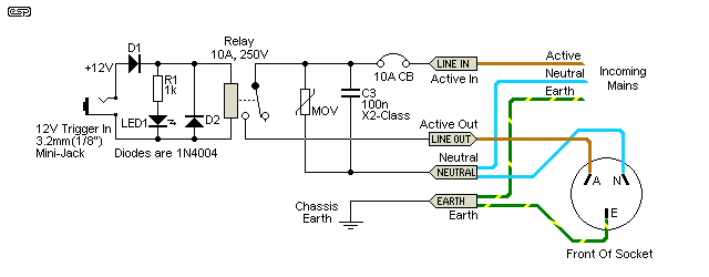
Figure 2 - Relay Based 12V Trigger Circuit
This is as simple as you can get. There are two diodes, D1 is to prevent reverse polarity from causing a short on the 12V line, and D2 suppresses the back-EMF from the coil when the power is removed. The case of the 3.5mm mini-jack socket (which may be connected to the sleeve) should be isolated from the chassis to prevent a ground loop. The VDR (voltage dependent resistor - usually a MOV - metal oxide varistor) and X2-Class capacitor are optional. The VDR provides some protection against voltage transients and the capacitor might help to remove some noise from the AC supply. See the section on using SSRs for info on selecting the VDR.
Note that all mains wiring must be done using mains rated cable, and must be separated from the low voltage side by a minimum of 5mm, but preferably as far away as possible. Never use Veroboard or other prototyping boards for mains, because the tracks are spaced too closely together and are very thin and cannot carry significant current.
Anyone expecting specific details on suitable relays will be disappointed, because I have to leave that up to you. The reason is very simple - there are thousands of suppliers worldwide, and a relay I can get easily here may be unobtainable elsewhere. The converse is also true, so it becomes a huge task to try to suggest something that's available everywhere. Check your favourite suppliers and see what they have in stock for a sensible price, and if it meets the requirements then it should be fine. If in doubt, have a look at the Relays article, which tells you everything you need to know about these components.
The things you will need to know about an electro-mechanical relay are as follows ...
Make sure that the relay you choose is specifically rated for mains usage. Never use automotive relays for mains - they are intended for low voltage operation (coil and contacts), and are completely unsuited for switching mains voltage. The coil current is also usually much too high, but that's a minor consideration against electrical safety.
The primary advantage of conventional electro-mechanical relays is simplicity. They are also extremely reliable if chosen wisely, which basically only means that the rated contact current is high enough to carry the load current - including any inrush current (which may be much higher than expected). Most allow peak short-term current that's greater than the continuous current specifically because many loads have a high initial current when first turned on. Electro-mechanical relays are electrically silent, because the contacts have extremely low (and more-or-less linear) contact resistance. Switching loss is extremely low, and the chance of spontaneous conduction (due to mains transients) is virtually zero. Electro-mechanical relays are usually very economically priced - expect to pay less than AU$5.00 for a 10A relay.
There aren't many disadvantages, but one is that the coil must draw current while the relay is energised, and this is wasted power. A typical 10A relay will have a coil current of around 40-50mA, so the power is usually less than 600mW. Relays designed for higher switched current will require a higher coil current. The contacts are subject to some erosion due to making and breaking the load current, so they will eventually 'wear out'. The typical life is generally around 100,000 operations at full rated load, and failures are uncommon. When operated, there is an audible click as the armature strikes the pole-piece, but this is rarely a distraction.
In some cases, the power amp may have its own internal power supply that's on permanently. Although it would be unusual to find an amp so equipped that didn't already have a 12V trigger, it's certainly possible. If you have such an amp, use the following circuit. Be aware that this circuit may create a ground loop, because the sleeve connection is common to both the controlling and controlled equipment. Optionally, you can use a 10 ohm resistor (R1) in series with the 'ground' pin and isolate the mini-jack socket from the chassis. This breaks the ground loop and usually eliminates hum caused by the loop.
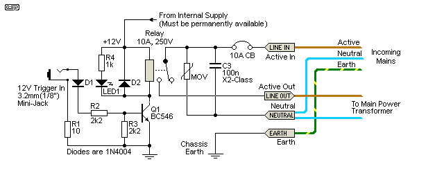
Figure 2A - Alternative Relay Based 12V Trigger Circuit
The relay coil voltage needs to be the same as the full-time internal supply, so it may be almost any voltage. You will need to verify that the internal PSU can deliver enough current for the relay, and in some cases it may be necessary to use a resistor in series with the relay coil to reduce an odd voltage to match an available relay. For example, if there's a 15V supply you can use, then the resistor is selected to drop 3V so the relay gets 12V (while 15V relays exist, they may be almost impossible to obtain).
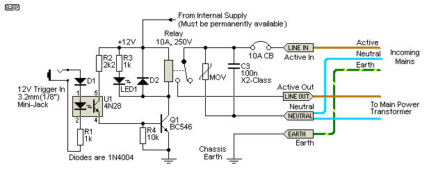
Figure 2B - Opto-Isolated Relay Based 12V Trigger Circuit
To obtain full galvanic isolation of the 12V trigger signal, the circuit shown above should be used. The opto-isolator will typically be a 4N28 or similar, and the sleeve connection of the trigger input jack socket must not be connected to the chassis - it's meant to be fully floating. When 12V is applied, U1 turns on, which in turn switches on Q1 and the relay. The opto-coupler needs about 10mA to be able to provide up to 2mA to the transistor's base, but this is negligible compared to direct powering a relay.
A solid-state relay (SSR) is often a good option, but there are a few traps for the unwary. If used at high current, a heatsink is essential because power dissipation is roughly proportional to the current drawn. Most SSRs will 'lose' about 1V RMS when turned on, so if your load draws 10A the device will dissipate 10W. You may think that the average current will be much lower with normal programme material, and this is certainly the case (other than Class-A amplifiers of course). However, the SSR may have little thermal mass and will heat up very quickly, even with relatively short-term transients. The heatsink will usually not need to be particularly large, but the thermal mass is essential to ensure that the semiconductor junction (usually a TRIAC) is kept below its maximum temperature at all times.
R2 has to be calculated based on the specifications for the SSR you use. For example, the maximum trigger current might be 50mA, but the recommended may be around 20mA or so, with a forward voltage of 3V. That means there is 9V across R1, so for a current of 20mA the resistance must be 450 ohms (use 390 ohms). This is simple Ohm's law. Many SSRs have built-in limiting resistors and specify a voltage range instead of a current range. Provided that 12V is within range, no limiting resistor is needed with these.
Be aware that some SSRs may be completely unsuitable for this application, because not all load circuitry provides an adequate holding current and you may end up with a very unfriendly mains current waveform that might damage some equipment. If you have any doubts whatsoever, use an electro-mechanical (conventional) relay, as they are unaffected by the type of load and perform just like a 'proper' switch. Before committing to using any SSR, I suggest that you run some tests first with the type you are considering. Any noise from the transformer or power supply that doesn't happen without the SSR in circuit indicates that there is a problem. If that's the case, use a normal relay instead.
Note: Switchmode supplies should not use an SSR, as the TRIAC will probably cause very high (and likely destructive) current spikes.

| Be aware that SSRs are available in two different types - random switching (aka asynchronous) and zero voltage (aka zero-crossing or synchronous) switching. If your controlled equipment uses a transformer, then the SSR must use random switching to avoid a large inrush current with every operation. |
Some sellers seem to be unaware of the difference, and assume that zero-crossing types are the 'most suitable' for general purpose applications. If your load is resistive or a switchmode power supply, this is true. However it is exactly the opposite of the ideal case for a transformer - especially toroidal types. For more info on this topic, see the Inrush Current article, which explains it in detail (along with oscilloscope captures). The information you need is often not provided, or requires considerable effort to gather - assuming that you have the part number for the SSR being offered. Note that the SSR shown in Figure 1 is NOT suitable for use with a transformer load, as it is a zero-crossing type!
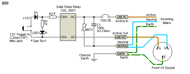
Figure 3 - SSR Based 12V Trigger Circuit
Where the VDR/MOV and X2-Class capacitor were optional for the electro-mechanical relay, they are essential when you use an SSR. A transient overvoltage can cause spontaneous conduction of the TRIAC, which will naturally be passed on to your equipment. Some electronics may be annoyed by this, and vent their displeasure by failing. I may be making assumptions, but I suspect that most people would prefer that this doesn't occur.
The MOV must be rated for the mains voltage where you live, so in 230V countries it will typically be 390V and in 120V countries it will be around 200V. You may need to talk to your supplier to determine the correct voltage rating, as the data sheets are not always clear. Voltage ratings are normally peak, although the appropriate RMS voltage may also be quoted in the datasheet.
As anyone who has read through the ESP projects and articles will be aware, I prefer electro-mechanical relays for any mains switching, because they are close to being bullet proof in terms of overall reliability. However, there may be some 12V trigger systems that can't provide enough current to power a traditional relay, so you may not have a choice.
The things you will need to know about an SSR are as follows ...
Like electro-mechanical relays, SSRs have advantages and disadvantages. The biggest advantage is that there is no arcing because there are no mechanical contacts that need to open and close, so the theoretical life is indefinite. Notice that I said 'indefinite' rather than 'infinite', because they are semiconductors and can fail (usually short circuit). The drive power is very low, usually somewhere between 5 and 25mA. They are acoustically silent which some people like, however, they are not electrically silent.
The primary disadvantage is that an SSR is a semiconductor. This means that there will always be some voltage lost across the switching device(s), so a heatsink is usually necessary. The dissipation is around 1W/amp, but most small SSRs don't have enough thermal mass to allow even brief periods of high current operation. The switching is electrically a little noisy, because there is a distorted waveform (of about 2V peak to peak, 1V RMS with resistive loads) across the TRIAC when it's turned on. Mains transients may cause spontaneous conduction which will last for up to one half-cycle of the incoming mains. SSRs are generally more expensive than their electro-mechanical counterparts, and this is especially true if you need to add a heatsink.
SSRs are susceptible to over-current and over-voltage. Unlike conventional relays the transient voltage needed for the relay to conduct is comparatively low. It's usually much less than 1kV, a voltage easily achieved during electrical storms or if there is a distribution fault. Excess current and a lack of a suitable heatsink may cause the die temperature to exceed the maximum permitted, in which case the SSR will usually fail short-circuit. All SSRs have a minimum holding current which some low powered equipment may not reach, and this can lead to unexpected malfunction in some cases.
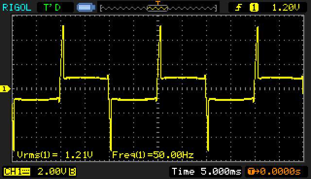
Figure 4 - Switching Noise From An SSR
In case you wondered about the noise referred to above, Figure 4 shows the voltage waveform across an SSR when it's on. The incoming voltage was 20V RMS, and the load was 16 ohms (1.25A resistive). The spike at the beginning of each half-cycle is there because the SSR can't turn on unless the voltage across it is high enough to allow triggering, about 5V as seen. This does not change with applied voltage, but the spike becomes narrower at higher voltages. The flat sections of the waveform show that there is ±1V across the TRIAC when it's fully conducting. This doesn't change much with current, and that's why there's a (roughly) 1W per amp dissipation in the device. An equivalent oscilloscope capture wasn't attempted for an electro-mechanical relay because it would show a tiny sinewave voltage due to resistance alone.
Because you are working with mains, construction is quite critical. You need to ensure that the unit is as close to being 100% electrically safe as possible. This means that all connections must be made in a manner that ensures they can never become detached, even if the unit is misused. Isolation between the incoming low voltage and mains voltages needs to be maintained, with separation of at least 20mm between the two circuits if possible. If an electromechanical relay is used, it should be attached to the chassis with a bracket and double sided adhesive tape so that it cannot be dislodged.
Solid state relays will usually have to be attached to the case itself (if it's made of aluminium) or to a heatsink. Make sure that there is plenty of clearance between the live mains connections and the chassis or heatsink. Most SSRs are fully insulated, so mica washers or similar aren't needed. When mounting an SSR, use heatsink compound (thermal 'grease') between the relay and the heatsink. All other connections (MOV and capacitor) should be to an approved terminal block or similar, with insulation as needed to ensure they cannot touch the chassis.
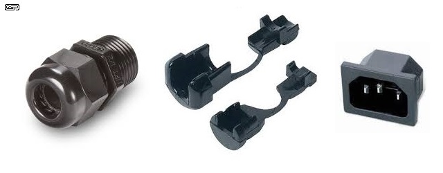
Figure 5 - Suitable Cable Clamps & IEC Connector
The incoming mains may be via a fixed lead or an approved mains connector. IEC connectors are very common everywhere, and are a good choice. If a fixed lead is used, it must be securely anchored to the case, and must pass through a suitable grommet to protect the insulation from cuts or abrasions. Do not simply tie a knot in the cable to prevent it from pulling out - it should be held securely with a cable clamp or cord-grip grommet as shown above. Optionally, you may include a fuse or circuit breaker in series with the incoming active lead. The fuse or breaker should be rated at no more than 10A in most cases (local regulations may limit the allowable current from switching or distribution boards). Active and neutral conductors should be joined using an approved terminal block.
If you use an IEC socket, try to get one that has lugs on each side to allow it to be held into the case with screws and nuts. The 'push-in' style pictured above requires a very precise rectangular hole in relatively thin material to ensure it can't come out, and that can be difficult to make with basic hand tools. If you do use a push-in type, then I suggest that it be additionally secured with a high strength adhesive (5-minute epoxy is usually good enough) so that it is held firmly in place.
| Wire Name (Oz) | Wire Colour ¹ | Also known as ... |
| Active | Brown, Red, Black | live, line, phase, hot, plus, positive (these last two are wrong, but I have seen them used) |
| Neutral | Blue, Black, White | cold, common, grounded conductor (US), minus, negative (as above for the last two) |
| Earth | Green/Yellow, Green | ground, protective earth, earth ground, safety earth, grounding conductor (US) |
Note 1 - Be careful with wire colours. The standards are gradually changing in many countries to the IEC standard of Brown, Blue, Green/Yellow, but a great deal of older equipment will use one of the old standards - and it might not be one ever used in your country! Make sure that you treat all incoming mains wires that are not connected directly to the chassis as hostile.
Make sure that the switching unit will not be overloaded by your equipment. 10A allows up to 2,300VA with 230V mains, but only 1,200VA with 120V. It may be necessary to use a larger relay (electro-mechanical or SSR) than indicated if your expected power requirements are greater than the figures given. The rating is in VA (Volt/Amps) because most audio-visual and hi-fi systems have a relatively poor power factor, and the power in watts may be as little as half the VA rating. Very few systems will exceed 1,000VA (1kVA) in normal use. I've only showed one, but you can have as many outlets on your switching unit as you like, but the total current must be limited to 10A with all equipment operating.
If the unit is built into a metal enclosure, the enclosure and all accessible metal parts must be connected to protective earth. If this isn't done and an internal wiring fault causes a live connection to contact the case, it can easily become an electric shock hazard if it's not properly earthed ('grounded' in the US and Canada).
Either of the circuits shown can be built as a stand-alone 'accessory', or built into your equipment if you are making your own power amps or subwoofers. The 12V trigger output can then be supplied from your preamp.
In some cases, you may have equipment that can be controlled (i.e. turned on and off) by a 12V signal, but nothing that actually provides the signal for the equipment to use. Fortunately, this is easily fixed by using a small power supply. It doesn't have to provide a great deal of current, but in some cases it may be required to power a relay, which will typically draw around 60-70mA (depending on the type). While it may appear to be a very simple process, you need to ensure that the 12V trigger signal has a fairly fast on and off time. This is particularly important with relays, and doubly so if it's a solid state type (SSR).
If the 12V rise and fall times are too long, it's possible that an electromechanical relay will not open and close the contacts in a timely manner, leading to arcing and horrible noises being produced. SSRs can be more difficult, as they may conduct 'half-wave' if the trigger voltage is allowed to rise and fall slowly. At some critical voltage, there is no guarantee that the SSR will behave itself. Ensuring a fast rise and fall time complicates the circuit a little, but it's very cheap insurance against malfunctions that may harm your equipment.

Figure 6 - 12V Power Supply With Rapid On/ Off Action
The circuit may look a little over the top, but it uses cheap and readily available parts to produce a very good end result. I's simply not worth taking the risk that a slowly rising or falling supply may cause a malfunction in the controlled equipment. U2 is wired as a simple comparator, and when the 12V supply has dropped to 11V, The output switch (Q2) is turned off very quickly. When power is applied, Q2 turns on fully the instant the output reaches 11.2V. The rapid on-off signal ensures that the controlled equipment cannot be in an 'indeterminate' state, being partly on/ partly off. R4 provides hysteresis, which ensures unambiguous switching.
The combination of R7 and Q3 forms a current limiter, which will limit the output current to around 100mA if the output is shorted (which will happen if a mini-jack is plugged in while the circuit is active). Q2 will dissipate a little over 1W while the short remains, and if you add a small heatsink (recommended) it should survive even long-term short circuits. If long-term shorts are expected, use a heatsink for the 7812 regulator (U1) as well, as it will get hot.
Note that U2 is a dual opamp. The second half is not used, and can be ignored or (preferably) wired as a simple buffer. Join pins 6 and 7, and connect pin 5 to ground. Do not substitute the opamp unless you know what you are doing, as it was selected because the output goes to 0V - most common opamps do not do this. You may also wonder at the use of a 15V transformer. That's recommended because it allows C1 to be smaller than normal, and also ensures sufficient current through R1 and the 10V zener diode. A lower current would make the reference voltage less stable. You can increase the value of C1 if you prefer, and a value of 1,000µF is a reasonable compromise.
The separate power supply may not be needed if a suitable source is available within the equipment. You do need to ensure that any existing source can provide the maximum current without it causing other problems, but if the supply is present (and capable) it would be silly to add another. Note that 3-terminal regulators generally can't handle the output from the main amplifier supply (usually ±35V or more), and if that's the only option you may require a simple pre-regulator to reduce the voltage to around 20V or so. Only a positive supply is required, and the pre-regulator doesn't need to be particularly accurate.
The circuits presented are all suitable for the job, but you need to make the decision as to which one you should use. My preference would be an electro-mechanical relay, because I wouldn't want the hassle of providing a heatsink. I also prefer that the mains doesn't get any more distortion added by an SSR, although in reality it's usually not a problem. Some people consider the click as an electro-mechanical relay operates as a 'problem', but if audible I prefer to think of it as confirmation that the circuit has operated and is doing its job.
You can also just experiment with the circuits for fun, but make sure that you always take proper precautions against electric shock. Don't work on anything while the unit is plugged in to a mains outlet, even if it's switched off. You can't always rely on the switch being in the active (phase or line) circuit, especially in older installations where it could be reversed with the neutral.
The Project 39 transformer soft start circuit also provides the ability to use a 12V trigger input. Although this isn't shown on the free public circuits, it's an option that can be included if you have the PCB. It expects that there will be a full-time low voltage supply present though, which isn't always convenient. It does have the benefit of extremely low current from the 12V trigger signal because that becomes easy when there is a voltage available all the time.
The sender unit will be useful for anyone who has equipment that uses 12V triggering, but nothing that provides the 12V output signal. A single switch can be used to turn on all equipment that supports a 12V trigger. If multiple devices need to be switched, they might include both a 12V trigger input and a 12V trigger output, or at least a 'loop' output (but I wouldn't count on it). Make sure that you don't try to draw more than 100mA in total, or the current limiter may prevent your equipment from turning on.
 Main Index
 Projects Index