
|
| Elliott Sound Products | Linkwitz Transform Circuit |
 Main Index
 Articles Index
From the editor ...
Project 71 has been a very popular project, and with good reason. Unfortunately, most people who have built it, don't actually know how it works. Jeremy Wolf wrote this article with some considerable consultation from Siegfried Linkwitz and a small amount from me. Since the Linkwitz transform circuit seems so mysterious (which it is), it is assumed by many readers of The Audio Pages (and others) that it must be complex. The mathematics certainly are, but the principle is not, as Jeremy explains.
There are caveats (of course) and compromises (which are a base requirement in every speaker ever made), but this article explains the overall benefit. I know the benefits well - a sealed equalised subwoofer will simply wipe the floor with anything else, provided that you have done your homework. Now, you don't even have to do that, since Jeremy has done it for you.
Q What is a Linkwitz Transform? A The Linkwitz transform was developed by Siegfried Linkwitz. It allows you to take a driver in a sealed enclosure that has an Fc and Qtc for that box and lets you "transform" or simulate a new Fc and Qtc for that driver in that box. Q How does it work? A Magic Q No seriously, how does it work? A It works by creating a precise equalisation curve to compensate for any peaking or rolling off that the driver is encountering. By doing this, a new Fc and Qtc can be assigned to that system.
Actually it is a simulation because you cannot physically change the Fc and Qtc of a closed system without actually making the box bigger or smaller or putting stuffing in the box and making it appear bigger. The following is an example of the above explanation with graphs to help clarify what is being said.
Ok, let's assume that you have a driver with the following specifications.
Fs = 33.5 Hz
Qts = 0.75
Vas = 46.1 litres (1.647 ft³)
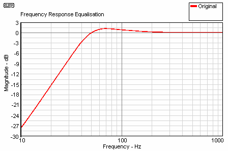
Now we are going to put this driver in a 38 litre (1.378 ft³) box. This will net us a Qtc of 1.0 This speaker in this box will yield the following results (these data can all be obtained from the Linkwitz Transform spreadsheet on the downloads page, courtesy of True Audio) ...
Fc = 49.6 Hz
F3 = 37.6 Hz
Qtc = 1.12
Vb = 38 litres

Figure 1 - Unequalised Speaker in 38 Litre Box
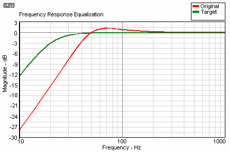
If you notice in this graph, there is a 1.2dB hump before the roll off occurs. While this response is ok for your average listener, we are not satisfied with it and want to change the response. Wouldn't it be nice if we could simply move the Fc down to say 20 Hz and have the Qtc = 0.707 to get a response that looked more like this ...
Fc = 20.0 Hz
F3 = 20.0 Hz
Qtc = 0.707

Figure 2 - Equalisation (Transformation) to Qtc = 0.707
As you can see, the green trace is the newly transformed response. It is much more suited for low frequency reproduction after being transformed. There will now be a much greater output in the lower octaves.
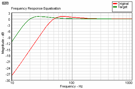
To show that the Fc is actually down at 20 Hz, here is a response of the same driver in that same box with after being transformed to a Qtc of 1.00 and Fc of 20 Hz. The slight peak causes the response to be 0dB at 20 Hz, and this response is easily created by the Linkwitz transform spreadsheet if desired.
Fc = 20.0 Hz
F3 = 20.0 Hz
Qtc = 1.000

Figure 3 - Equalisation (Transformation) to Qtc = 1.0
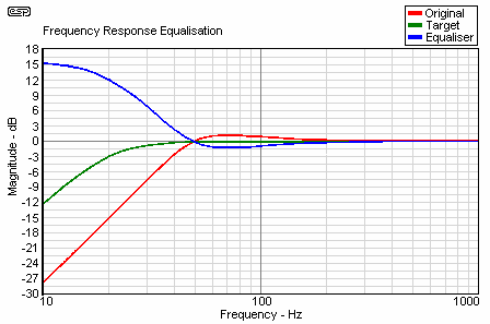
Getting back to our desired response of Qtc .707 and Fc of 20 Hz. The graph in Figure 4 shows the compensation that the Linkwitz transform is using in order to flatten out the response curve of our driver.

Figure 4 - Equalisation Applied by Linkwitz Transform Circuit
The red line represents the original driver with a Qtc of 1.0 and an Fc 49.6 Hz, F3 of 39 Hz. The blue line represents the equalisation curve that the Linkwitz transform is supplying to the amplifier in order to compensate for the new Qtc and Fc. The green trace is the combined response which now has a -3dB frequency of 20Hz. The transform is cutting out 1.2dB in order to compensate for the Qtc of 1.0, which is causing a 1.2dB, boost around 70 Hz. It is then providing boost at the lower frequencies at a rate that is equal to the natural roll off of a sealed enclosure. Instead of rolling off at 12dB an octave, the speaker is being forced to maintain a flatter response due to the amplifier giving it a lot more power at the lower frequencies. For example at 20 Hz, the amplifier is giving the speaker an additional 12dB of gain, or 16 times more power than at frequencies above 50 Hz.
Getting this kind of response out of a sealed enclosure setup requires some tradeoffs. You will be giving up some of the overall SPL producing capability of the driver because of the excursion overhead needed at the lower frequencies.
If your speaker is flat down to 50 Hz and you want to extend one octave below that to 25 Hz then you will lose 12dB of overall output capability when producing sound at 25 Hz because you are using up all of the driver's excursion and most likely power handling capability too.
We'll say that we have an imaginary speaker that has these basic parameters ...
| Efficiency | 88dB/m/W | |
| Xmax | 4 mm | |
| Max Power | 250W |
The driver is in a sealed box with a Qtc of 0.707 (optimally flat). We'll also say that it is flat down to 50 Hz, and at 50 Hz it is capable of producing (just under) 112dB SPL at full rated power. Let's say that the speaker is in a sealed enclosure, and an equaliser will be used to obtain the last octave (down to 25 Hz).
Below the Fc of 50 Hz the speaker will roll off at 12dB / octave. That means at 25 Hz, the output of the speaker will only be 100dB. To obtain the same 112dB output as before, you will need 4 times the excursion and 16 times the power (i.e.4,000 Watts!) as at 50Hz. This is because for every octave lower that you want the speaker to produce you need 4 times the excursion, and in order to obtain the excursion in an equalised system, you must have 16 times the power. To put this another way, excursion is equal to the inverse square of frequency. Half the frequency, four times the excursion, one quarter the frequency, sixteen times the excursion (etc.). The power requirement is the square of the excursion. To lower the response by two octaves (¼ frequency) you need 16 times the excursion and 256 times as much power. In general, try not to exceed one octave if possible, as excursion and power requirements rapidly get out of control.
So, now that our speaker does not roll of at 12dB / octave (because of the equaliser) and maintains a flat response to 25 Hz, it will need to use 4 times more excursion and 16 times the power to produce 25 Hz at 112dB.
Now comes that tradeoff part that I was talking about before. The driver is using all of its power rating and 1 mm of its 4 mm of Xmax to produce 112dB at 50Hz. Now we want to achieve a flat response down to 25Hz by using the Linkwitz transform. That means we will be trading off some of our 112dB SPL to gain some low frequency flat response. The speaker will be using 4 times the 1 mm Xmax or 4 mm of excursion to produce this 25 Hz frequency. The power needed is well in excess of the speaker ratings, so must be limited to 250W.
If we want to use this speaker in the transform, we now need to trade off 12dB total maximum output for a total maximum output of 100dB that is flat from 25 Hz up. That's not too bad of a trade in my opinion. But remember, this is only an imaginary driver that I made up, not a real world example, although in reality, most "real" speaker drivers will not be all that far off. Every 3dB increase in SPL requires double the previous amount of power. And in our case we needed 12dB of gain which is 16x more power.
The two things to remember from this example are ...
Power compression is another aspect that should be considered. This occurs when any loudspeaker is driven with a significant amount of power. The voice coil heats up, and the available power is reduced accordingly. Depending on the program material, you may easily lose 6dB of SPL because of power compression (assuming that the system is being pushed to its limits). Power compression cannot be compensated for by using more power, as it is dynamic in nature. The effects are (perhaps surprisingly) not as noticeable as one might expect, since sustained high power at extremely low frequencies is rare in virtually all normal program material.
Fortunately, this is not as big a problem as may be imagined, since typical low frequency energy levels are actually surprisingly low most of the time (see Power Distribution below). Home theatre systems will be called upon to reproduce large amounts of relatively deep bass, but only for short periods at a time.
With most music, there is very little energy below 40 Hz, so power and excursion are not normally a problem. Pipe organ music is an exception - the 64' pipe on a full pipe organ is 16 Hz, but it is not used a great deal - in some cases because of the structural damage it does to the building housing the organ! If you are an aficionado of such music, I suggest that you use the largest box you can, with a very large driver. It may be wise to reinforce your home while you are at it (and no, I'm not joking).
With the explanation and examples out of the way, you might be wondering what kind of specs to look for when choosing a driver. Here are some guidelines that should help you.
These guidelines are just that, only guidelines. One thing that you need to be careful of is the excursion and the power the driver can handle. I say this because these are the two that will damage your precious driver if you exceed them by too much. When I first did my setup, I thought that a single 300 mm (12") driver would be more than adequate based on my equations for excursion and amount of surface area they had. I was wrong because of my seating location and the room that I was placing them in. Don't get me wrong, a single 300 mm sounds awesome, but 3 x 300s is absolutely unreal because I can hit 105dB at 25 Hz from my listening position. My listening position also happens to be the place with the best bass response in my room.
I was in the process of building a Linkwitz Transform cct for my 305mm (12") sub. ESP said in the articles about ELF and EAS that low frequency content in music has much lower power levels than the power calculations would suggest. I decided to investigate this, and digitised some tracks off various CDs with various styles of music.
My sound editor gives the WAVE graph amplitude in 16bits (-32000 to 32000). I then performed a low pass filter of 40hz on the track and found the highest peaks, then compared them to the highest peaks of the full range signal, and did a dB calculation ...
20 log ( V ) (where V is the 16bit amplitude)
Typically, I got (digital) peaks of +/-30,000 for the full range signal, and only +/-4,000 for the < 40hz signal. This is a 17.5dB difference. The results are tabulated below.
| Music Type | Relative Level at <40Hz |
| Rock music | - 13dB |
| Maria Carey Song | - 15dB |
| Rap Music | - 14dB |
| R&B song | - 12dB |
| Rave track | - 12dB |
| Second Rave Track | - 21dB |
| Vinyl Bass Track | - 11dB |
| Rave track with bass sweep | - 9dB |
| Average | - 11.875dB (12dB) |
These figures would suggest that boosts of around 10-12dB are possible with the Linkwitz circuit, before any extra amplifier power is needed above that which is required for the frequencies above 40hz.
1. There is a strong case for applying a highpass filter at between 5 and 15 Hz. This prevents excessive excursions at sub-audible frequencies, and offers a measure of driver protection. Ideally, this filter would have a steep slope (12dB / octave minimum), but a simple 6dB (first order) filter can still be used. The filter may be before or after the Linkwitz transform circuit, having the same effect regardless of physical position.
Use of any filter will have an effect on the actual response of the completed system, however this is generally small, causing perhaps a 2dB error at 20 Hz. It is probable that virtually any room will create errors many times this figure, so it can generally be discounted.
2. There is a recommendation in the spreadsheet (see downloads page) that great care is needed with a maximum boost over 20dB. I think that this is understatement, and care is needed with any boost above about 10dB. The increase in power and cone excursion becomes extreme, although with most music, the actual energy level of signals below 40 Hz is relatively low.
There are some exceptions to this, and it should never be assumed that you won't need the power or excursion - someone will eventually prove you wrong.
3. You must remember that the box is sealed. The pressure exerted by a 380 mm (15") cone with an Xmax of 10 mm will literally split the seams of a box that is not sturdy enough (it apparently happens quite regularly with a certain well known subwoofer using a similar principle). The box must be as strong as you can make it - screwed, glued, and substantial internal cleats at all joins are essential. There is no such thing as a box that is too strong, but make sure that you account for the volume occupied by the strength members when you do the calculations). Bracing is usually not needed, since the frequencies are so low that panel resonance is unlikely if the unit is a self contained subwoofer. All panels should be of 18 mm (minimum) sturdy ply or medium density fibreboard (MDF) - do not use chipboard, the box will not hold together!
4. The use of a small (say 5 mm) vent stoppered with felt to present a significant resistance to airflow is also a good idea - especially if the woofer does not use a vented polepiece (via the dustcap). This allows air pressure to equalise slowly, since you will have to expend considerable effort to make sure that the box has no air leaks. If present, any leaks may whistle or make some other equally undesirable noise when the subwoofer is in use. It is unlikely that you will be able to blame the dog for these noises (in case you thought you might get away with that excuse). 
5. The Linkwitz transform circuit is available as a PCB with full construction details. The board incorporates a 15 Hz filter (this can be changed) and uses one dual opamp. To have a look, see Project 71.
6. My thanks to Jeremy for putting this article together. His efforts have saved me an enormous amount of time, and the article is written directly for the beginner or relatively non-technical reader. As many of you may have noticed, this is something I often have trouble with 
7. I would also like to thank Gareth for his contribution, which is a useful addition. The power calculations he did are somewhat more scientific that the "gut feel" method I had applied - even though the net result is much the same. 
A special thanks goes to Siegfried Linkwitz for verifying this document and helping me explain in simpler terms what his circuit is doing.
Jeremy sent me an e-mail from a reader, who pointed out a couple of errors in the calculations for excursion and power. I have amended the "offending" section, which is now (hopefully) correct.
14 Sept 2002 - Added Gareth's power calculation information. 
 Main Index
 Articles Index