
|
| Elliott Sound Products | Build a 30 Second Timebase |
 Clocks Index
 Main Index
The original version of this idea was published in 2010, but it is only suitable for clocks that use a 1 second timebase. See 1 Second Timebase for the background and how to derive the 1 second pulses from a quartz clock PCB. However, there are clocks (notably the Gent and Synchronome) that require a 30 second impulse for their slave movements, and this is harder to achieve if you don't happen to have the master clock to provide the impulses.
You will also need to refer to the Alternating Polarity Clock Motors article to determine the drive circuit you need. This article deals mainly with the issue of obtaining a 30 second impulse. Once you have a source of 1 second impulses, you need to divide by 30 to obtain one pulse every 30 seconds. The way I've done it is basically 'brute force', in that no specialised ICs are needed, and a couple of standard and readily available 4017 CMOS ICs are bludgeoned into doing what we need.
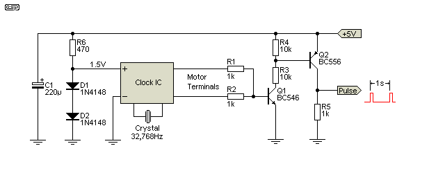
The first section of the circuit shown expects a 5V pulse at 1 second intervals. The pulse can be derived from the circuit shown in Figure 1, in turn based on the various options shown in the 1 Second Timebase article. It uses a quartz clock IC that can be cannibalised from a standard quartz motor. While the mechanical parts have a finite life, the IC normally lives close to forever.
The two transistors combine the output pulses. One pulse is produced at each output every two seconds, so both have to be captured to get a 1 second timebase. One would normally expect that the outputs would be combined using diodes, but the method shown works better. The pair of diodes and R6 are used as a crude voltage regulator to provide the 1.5V needed by the clock IC. The crystal will be included on the PCB when its removed from the movement.

Figure 1 - Pulse Generator Using A Quartz Clock PCB
This is not the most accurate timebase known, so if you are expecting high precision you may be disappointed. You can use a GPS module which is far more accurate, but I'm not going to provide the details for that unless there is some interest. The Figure 1 circuit is non inverting, so the voltage is normally at zero, and pulses high (to +5V) once a second.
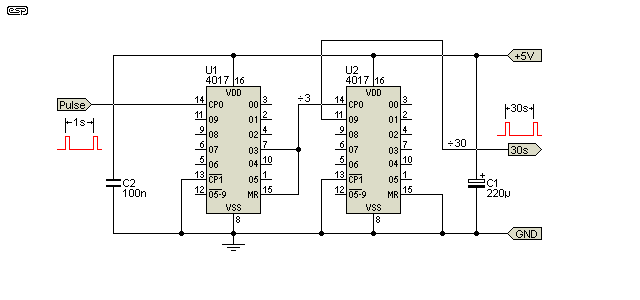
Now that we have a timebase, we can look at generating 30 second pulses to suit slave clocks that expect this. A pair of 4017 decade counters are used, with the first one set up so that it resets itself after 3 counts, so divides by three. The second 4017 operates 'normally', and divides by 10.

Figure 2 - Divide By 30 Stage
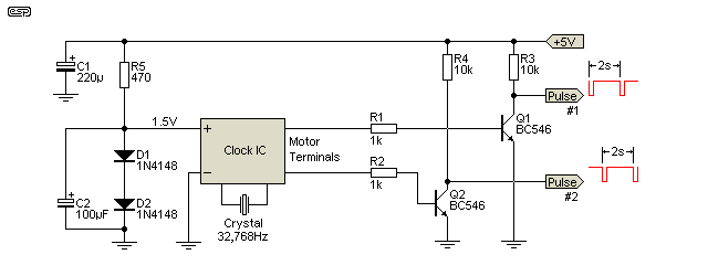
The output from Figure 2 can now be sent to a suitable alternate pulse driver as shown in the Alternating Polarity Clock Motors article. However, rather than building a complete alternating pulse circuit, you could simply build two of the circuits shown above, and drive each one from an output from the quartz clock IC. This requires a modification to the Figure 1 circuit, as shown next. This may appear to be a rather crude way to achieve the result. While that is certainly true, it's also by far the simplest and cheapest option.

Figure 3 - Dual Pulse Driver Circuit
Each of the pulse outputs goes to its own divide by 30 stage. Although this does use up a few more ICs, they are cheap, and it eliminates the need for another circuit to split the pulses again to drive the motor circuit (Figure 4 in the Alternate Polarity Clock Motor article). The alternative is more complex, and requires quite a few more parts. There is a small disadvantage, in that the output is directly from a CMOS IC, and they can't provide much current. This is dealt with in the motor driver.

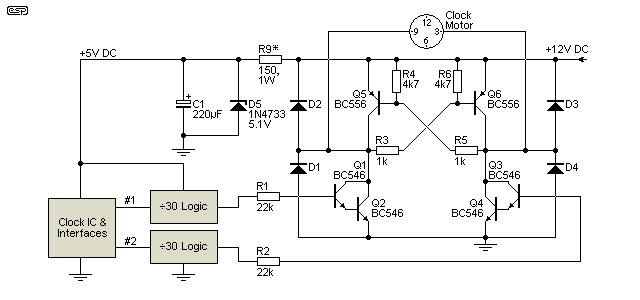
Figure 4 - Alternating Polarity Motor Drive Circuit
The above shows the general principle, based on a motor that's rated for 12V. The clock and interface circuit is from Figure 3, and it uses two of the Figure 2 divide by 30 stages. Each pulse to the transistor drive circuit will last for about 3 seconds - a bit longer than ideal, but it's unlikely to cause any damage to the motor. If you have a slave clock that expects a voltage greater than 12V, you will need to increase the supply voltage accordingly.
R9 will need to be increased in value with higher voltages. The aim is to provide a zener current (D5) of no more than 50mA. For example, if you use a 24V supply, R9 will have to be increased to 390 ohms and rated for at least 2W. You may also want to increase the power rating of R3 and R5 to 1W for voltages above 12V or so. The circuit is slightly different from that shown in the alternate motor article, because the drive level for the input transistors is limited. The Darlington pair shown (Q1/Q2 and Q3/Q4) have much higher gain than a single transistor so they require far less base current to switch the motor.
The techniques shown here should work fine, but be warned that they have not been built and tested. Much as I'd like to be able to build each and every circuit I publish, there are too many, and in some cases I have to resort to simulations using a computer program that analyses the circuit behaviour. Simulations show that the circuits will perform as expected, so you can have high confidence if you build them.
The circuit isn't restricted to clocks - any application where a fairly accurate 30 second timebase is needed can use the schematics shown. You won't find anything else that gives the accuracy of the method shown for anything like the cost (which is peanuts). Needless to say, you can use a GPS receiver if you need extreme accuracy.
 Clocks Index
 Main Index