
|
|
| Elliott Sound Products | Driving Slave Clocks With Arduino |
 Main Index
Clocks Index
Main Index
Clocks Index
Over the years there have been a number of variations in the timing and polarity of output pulses from master clocks. I was given a very old slave clock that requires a 1 minute alternating polarity pulse. One of my master clocks produces a 1 minute pulse but it is only a single polarity so this became the inspiration to find a different and easy way to generate accurate pulses to drive slave clocks.
My 100 year old slave clock is now a happy clock, Tick Tock happy clock.
Happy to be going and happy that no-one ripped its soul out and stuck a quartz thing in there. So if you want to drive an old slave clock and save it from mutilation read on.

|
| Please Note: The RTC board includes a 'button' cell (battery), and these have been responsible for the death of many small children worldwide. When swallowed (something that small kids often do), the cell may lodge and discharge inside the oesophagus, leading to severe burns, penetration of the oesophagus lining, leading to serious injury or death. Please feel free to do a web search for 'button cell deaths', and note the number of references you'll find. Make sure that the cell (and any spares) are kept well away from anywhere that toddlers can reach. |
I looked at Arduino and it looked cheap but where do you start?
Arduinos are very simple single core processors that can only deal with one program thread at a time. You attach bits to them so you can get them to interface with the world. They run on software that you can write in standard ASCII text format (e.g. Windows Notepad, Notepad++, etc.), and then cut and paste the program into the specialised Arduino software that your PC will load into the Arduino via the USB port.
There is a lot on the net, so look up 'blink' and get that working, now fiddle with the program to make a pulse generator that will drive a relay, then you can drive a slave clock. (The 1000 is milliseconds, change the value to 30000 and 40, now you have a 30 second pulse generator, with a duration of 40ms).
However, it isn't that accurate, so you need something that has a stable time base, which brings us to the Real Time Clock which has an integrated temperature compensated crystal oscillator.
There is heaps of stuff about using a RTC on the net and how to connect to a Nano and couple it with a display to make an accurate clock, but we don't need the display as we only need an accurate pulse to drive a slave clock ... which is our display.
If you look at the RTC module you will see there is a square wave output and the first thought is to program the Arduino as a frequency divider to produce the appropriate pulse.
It's not that easy unfortunately, as the Arduino is a very small single thread processor, and if it's busy dividing pulses and then goes to generate the output pulse it will miss the incoming pulses and won't keep time. It has stopped counting while doing something else. It's a single thread processor.
So instead we read the time continuously and then when we get to the correct number of seconds, generate the pulse.
We don't need to set the time in the RTC as we are just using it as a seconds generator. We don't care about the minutes, hours, days or years. We just want accurate seconds we can count, and then use to produce an accurate pulse to drive a slave clock. The DS3231 RTC is accurate to 2 ppm (parts per million) which is the equivalent of just over ±1.0 minute each year.
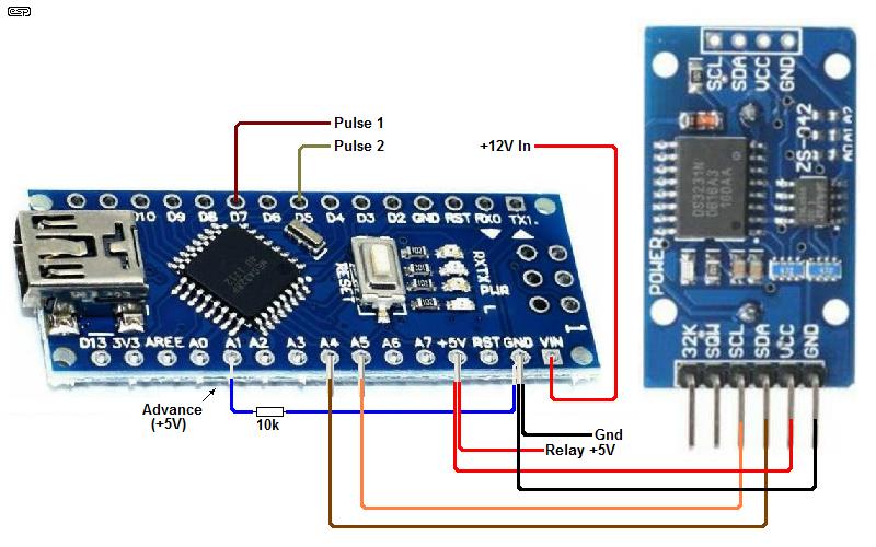
Figure 1 - Arduino Nano And RTC (Real Time Clock) Wiring
The basic circuit is shown above. The Arduino Nano is shown, but you can also use an Arduino Uno, ensuring that the pin numbers and positions are changed (as required) to suit. There is provision for an 'Advance' button connected to pin A1 (Nano Pin 15). The final configuration you use may be different from that shown, depending on whether your slave clock is single or alternating polarity, the drive voltage (or current) required, etc. Many slaves are designed for a specific current rather than a voltage, although the two are defined by the motor's coil resistance. Low resistance coils are usually designed for a particular current, and once you know that (and the resistance) you can work out the voltage with Ohm's law.
Slave clocks come in a number of variations but they are all current operated as they use an electro magnet to operate the mechanism.
There are 2 common variations ... a single polarity pulse or an alternating polarity pulse.
The difference lies in the magnetic circuit.
A single polarity clock will be constructed with a magnetic pole piece and armature (the bit that moves), but they are not magnetised until current is passed through the coil. The armature is then attracted to the pole piece, and the mechanical movement advances the clock. An alternating polarity clock has a magnetised rotor rather than a hinged armature, and the driver reverses the magnetic field with every pulse so as to cause the rotor to turn by 180°. Every pulse magnetises the stator (the magnetic circuit with the coil) with alternating polarity, causing the rotor to turn each time. If powered with a single polarity, the motor will not turn.
So 2 different programs are required to drive our slave clocks as we may need either a Single polarity pulse or an Alternating polarity pulse.
The time between pulses also needs to be variable and clocks can require anything from 1 second to 1 minute single or alternating pulses.
The 30 second single polarity slave is fairly common and typical of 1950s clock systems such as Gents and Synchronome. There are also many alternating polarity slaves, again including Gents, Plessey (see the Plessey movement in Alternating Polarity Clock Motors), and countless others.
The Arduino has a very limited current output and its voltage is limited to 5V, so we need clock driving circuitry to handle the current requirement of the clocks electromagnet.
A relay board will do what's needed. This allows the clock to be driven by an independent supply, normally 12 Volts is adequate with an appropriate resistor chosen to limit the current. You can use any type of battery of convenient voltage but I found a 12 Volt, 7 Amp Hour SLA (sealed lead-acid) battery cheap and convenient with plenty of off the shelf trickle chargers available ... and it was in my parts pile.
This kind of set up makes a cheap un-interruptible power supply.
This is not meant as a step by step guide. There is a lot of choice in what boards you choose to use for driving the clock.
The pulse width needs to be considered, look in the code and find the 'relayOnTime' This sets the width of the pulse in milliseconds. 40ms seems ok for most clocks, when driven by relays, as they have a slow release time which 'stretches' the pulse. It may be necessary to increase the time if electronic switching is used to ensure reliable operation.
A single pulse of the same polarity just needs a single relay or ½ of a stepper motor driver, where an alternating pulse slave clock needs to be driven through an H-Bridge. Alternate drive can be provided either with two relays wired appropriately, a stepper motor driver, or a simple transistor circuit.
Read the instructions for your relay or motor board and connect it to the Arduino output pins. The software for a relay board or a motor control board are the same. If you build a transistor driver you'll already be well versed on how it works, since you built and tested it.
Be wary here, some relay boards are turned on with a negative pulse and some don't turn on with the Arduino. Read the specs. Generally optocoupled relay boards function quite happily. Be careful if the relay boards use 5V relays, because the regulator on the Arduino is not intended to supply significant output current from the 5V output terminal. If possible, use relay boards that are powered from 12V, so they can be powered directly from the battery, and don't stress the on-board regulator.
The program in this article generates positive pulses to drive the relays, you can change the 'high' to 'low' if you fiddle with the software. Change all the 'low' to 'high' and 'high' to 'low', but only if your relays turn on with a negative pulse. For example, some optocoupled relay boards expect the 'operate' pin to be grounded to activate the relay.
The Gents 30 second slave is very common. Referring to the Gents specifications they were set up in the factory to operate on a minimum of 0.13 amp single polarity pulse.
A working current of 0.22 amps is specified so with a 12 volt battery a current limiting resistor of 56 Ohms connected in series should be fine when using a relay board. You can drive multiple clocks connected in series by selecting the correct value of current limiting resistor.
If your clock is an unknown this is a good place to start. However, you also need to be aware that some Gent slaves use a 30 second alternating pulse, and require up to 20V to operate reliably.
When the operating current to an electromagnet stops the collapsing magnetic field produces a back-EMF and a spark is produced across the switch. This spark will eventually destroy any relay contacts so it needs to be suppressed, it may take out motor board transistors. If there is no resistor in parallel with the clock's coil, add one. A resistor 10x the DC resistance of the clock coil is adequate spark suppression. This is a very 'old school' method for limiting the arc voltage, and was used in many of the earliest electrical clocks made, by many different makers. You can use other methods (such as diodes or zener diodes), but the resistor technique works well with low voltages, and resistor dissipation is low.
There is often no resistor on the slave clock as the spark suppression circuit was located in the master clock. If the clock motor winding is (say) 10 ohms, then a 100 ohm resistor will limit the peak back-EMF to 10 times the voltage applied by the relays or other switch. If the voltage across the energised coil is (say) 2.2V, the 100 ohm resistor will limit the back-EMF to 22V, which will cause minimal arcing.
I have kept this as simple as possible and the time adjustment is a single pole switch that forces pin 15 high and steps the clock at 1 second intervals. Pin 15 is labelled as A1 on the Nano board and requires a 10k pull-down resistor (i.e. the pull down resistor is connected to ground and the switch to +ve). Operating the switch drives pin 15 high and steps the clock at 1 second intervals
If you don't tie A1 low with a resistor, you may get random pulses from stay electric fields, false triggering the input.
The RTC is accurate to 2 ppm. If you want to set the seconds count against an atomic clock add the following code and hit the Reset seconds zero.
//Place at top of file, set number to desired pin
int zeroTime = 17

//Place in loop
	if(digitalRead(zeroTime) == HIGH){
	rtc.setTime(0, 0, 0);
}
So here are the 2 sets of code. These are easily cut and pasted directly from this web page, and the formatting should work without any changes.
One Minute Alternating Pulse Clock Software
To copy the code, left-click inside the text box, and hit CTRL-A to select all, CTRL-C to copy. The code can then be pasted (CTRL-V) into your code editor.
To change for a 30 second alternating pulse clock change the line shown below ...
	change	if(!triggered && seconds1 == 0)
	To      if(!triggered && seconds1 %30 == 0)
As before, To copy the code, left-click inside the text box, and hit CTRL-A to select all, CTRL-C to copy. The code can then be pasted (CTRL-V) into your code editor.
The output is labelled D5 and D7 on the Nano and UNO for the alternating polarity pulse. The output is labelled D5 on the Nano and UNO for the 30 sec single polarity pulse. If you want to use a UNO the on board pin designations are the same except for SCL and SCA which are designated as such on the UNO board.
A5 and A4 are the labels on the Nano board
SDA and SCL are defined in the Nano and the RTC library is loaded by the first 2 lines of code.
#include <DS3231.h>

DS3231 rtc(SDA, SCL);
You'll need the DS3231 library too. There are several on-line, but the only one that I know works can be Downloaded Here.
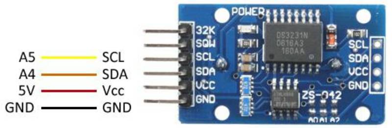
Figure 2 - Arduino RTC (Real Time Clock)
V-supply is as required and you need to calculate the correct value of the series resistor (Rseries) to provide the correct current for your clock. This is shown as 'SOT' - Select On Test.
Figure 3 - Relay Wired As An 'H-Bridge'
When Relay1 operates, power is supplied to the slave motor from the right side, so the right pin of the motor receives a positive pulse for the switching duration (i.e. around 40ms). The relay then turns off again. When Relay2 operates, the motor's current flow is reversed, again for 40ms. In the 'off' state (both relays inactive), the clock motor receives no power. It is short circuited, but this is of no consequence, and may even help some motors 'lock' to prevent unwanted movement (this depends on the motor's construction, with most not caring one way or another).
Figure 3A - Transistor 'H-Bridge'
For minimum power consumption, the transistorised 'H-Bridge' is a better proposition. While it may take some clock people out of their 'comfort zone', it's easy to wire on a tiny piece of Veroboard, and it has very low power consumption. The four diodes are 1N4004 or similar, and they provide back-EMF protection, as well as extending the pulse duration slightly. Most clocks that use a coil rated for 12V or more can be driven, and a series resistor usually will not be needed. Note that the circuit is designed for low current, so attempting to drive a low voltage, high current slave movement will not work. The clock that this drive circuit is used for runs most happily with 40V, and the motor coil's resistance is 3kΩ, giving a coil current of 33.3mA. The two inputs must never be driven high simultaneously or the transistors will be destroyed. Fortunately, the code provided doesn't let this happen (provided you don't mess up the code of course).
Note: There was an error in Figure 3A, which has now been corrected. My apologies to anyone who could not get it to work. (Corrected Aug 2020)

Figure 3B - Transistor 'H-Bridge' On Veroboard
The above photo shows the one built by ESP, and it's much larger than full size. The piece of Veroboard is only 45 × 18mm, but it could have been made smaller easily. The one pictured was built to test it out, and it ended up becoming part of the clock driver. Realistically, it could be reduced to about 30 × 12mm, but there really isn't any need. The junctions of the diodes have been used as the output 'terminals'. Excluding the piece of Veroboard, the cost of the whole circuit is under AU$3.00 for the parts. Yes, you can likely buy a relay board for less, but it's far less efficient.
If you look on Aliexspress or ebay, Arduino boards are as cheap as chips with free postage. You just have to wait a while for it to arrive. Buying from ebay usually is more expensive, but you also have a bit more protection than is provided by Aliexpress.
RTC - USD 1.00
Nano - USD 2.10
Dual relay Board - USD 1.30
This is not meant as a step by step guide. There is a lot of variation in what board you choose to use for driving the clock.
When I powered the Arduino from my PC USB I found the odd pulse was missing. I put this down to the PC going into sleep mode.
The electronics are mounted on a slide out shelf above the battery, which gives easy access. The battery is charged with a 'wall-wart' type charger, with means I don't have to fiddle with mains wiring. I did one setup with a Nano on Veroboard but the set up with jumpers is easy and works fine.
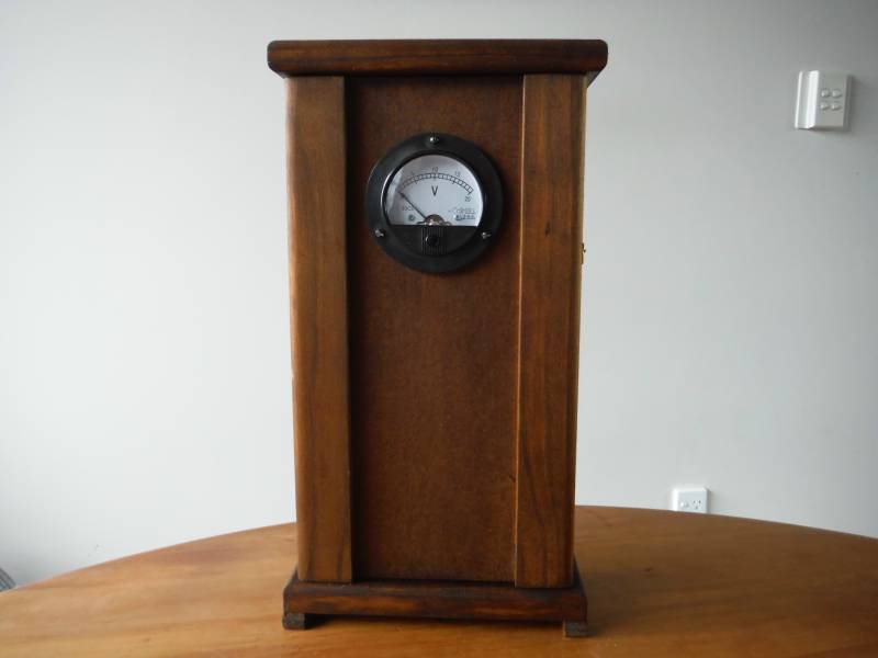
Figure 4 - Unit In Case
The author included a voltmeter, which is a nice touch. This shows the battery voltage, which may be particularly important during a sustained blackout. Should the voltage fall below 10V, the system should be turned off to prevent damage to the battery. SLA batteries are generally susceptible to internal damage if discharged too far, so the state of charge is important.

Figure 5 - Arduino, RTC & Relays
Note that the two photos above show an Arduino UNO, rather than the Nano referred to in the text. For the most part, they are interchangeable, and you can use either. There are many different relay boards available, but you can make your own using Veroboard, with a pair of relays, a couple of low-cost transistors, two resistors and two diodes. The basic circuit is shown in Figure 8 of Alternating Polarity Clock Motors, and the Arduino connects to R1 and R2 (omit the capacitors, and reduce R1 and R2 to around 2.2kΩ).
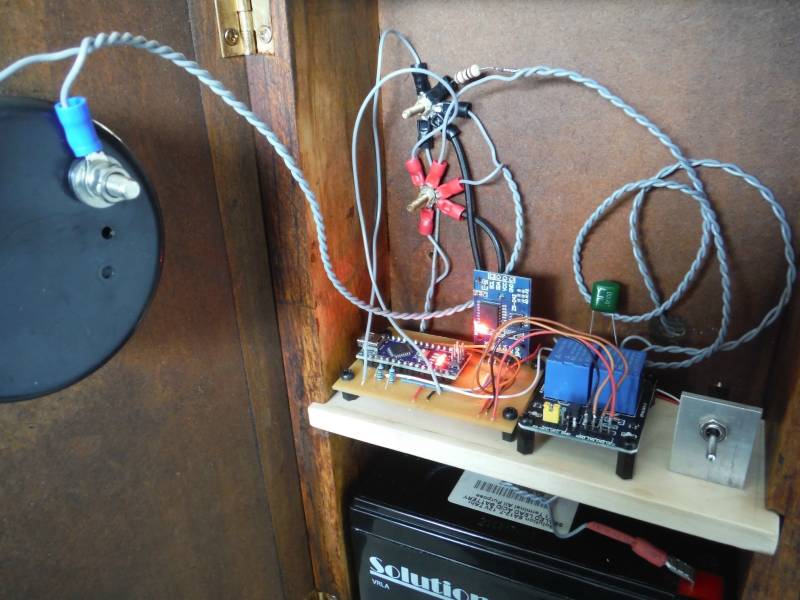
Figure 6 - Inside The Case

Figure 7 - Slave Clocks

The article Alternating Polarity Clock Motors shows the general principles of driving alternate polarity clock motors in some detail, and it includes a fully 'solid state' (i.e. no relays) H-Bridge that can be used (which is very similar to the board shown above). The article also explains in some detail how these motors work, and for people who have not encountered these before it will give some background that isn't repeated here.
The techniques shown here rely on some basic familiarity with Arduino boards, and the programming thereof. The use of an Arduino can provide very good time-keeping (with the real time clock board), and it's a good solution for people who can work with the code and want a very accurate signal for their slave clock(s).
Please note that the code shown is provided 'as-is' and there is no guarantee (express or implied) that it will work without changes. As shown, it has been tested and run by www.longfellowclocks.nz (the author, and by ESP), and it's believed to be without transcription errors. The article is contributed, and I have a limited ability to assist readers who run into difficulties. Note that Arduino boards have on-board regulators, and can be powered from any wall-supply that provides up to 12V DC. Since there are so many different suppliers of these boards, it's your responsibility to ensure that the wiring and supply voltage are correct, and that the connections are made exactly as described. While the www.longfellowclocks.nz version is shown with plug-in jumper leads, I recommend that all connections be soldered for long-term reliability.

Figure 8 - ESP's Slave Clock Driver Circuit Board
The photo above shows the controller I built to drive a Gent 30s alternate polarity clock. Because the coil measures 3kΩ, even with 40V applied the current is only 13.3mA, and it needs a 500ms impulse to get reliable operation. The motor is shown in Figure 2 in the Alternate Impulse Motors article. Prior to contact from longfellowclocks.nz I hadn't tried to get this particular clock running, because it was too irksome to do using 'traditional' logic. The high voltage needed also caused some heartache, until I developed the simple circuit seen in Project 193 (or the lower voltage version shown as Project 192), which turned out to be ideal. I used the prototype that I built to ensure that the circuit works as claimed, since it didn't seem sensible to build a new one when I already had one that didn't have any real purpose in life.
The whole circuit as shown is only 75 × 70mm, and runs from 12V DC.
Main Index
Clocks Index