
|
|
| Elliott Sound Products | Project 193 |
 Main Index
Projects Index Main Index
Projects Index
|
PCBs will be available for this project based on demand. The same PCB will also be applicable for Project 192.
Following hot on the heels of Project 192 (±12V from a single 12V supply), the exact same topology can be modified ever so slightly to get a +48V phantom power supply. There are few changes needed (one resistor!), and if it comes to pass that a PCB is made available (which depends on demand), it will be suitable for either application. As with the original 24V boost converter described in P192, the available current depends on the inductance used. Also in common with P192, the output needs good filtering to ensure that you don't inject switching noise onto the phantom supply.
Phantom powered gear can draw a maximum of about 12mA, because the current is limited by the standard 6.8k resistors (often shown as 6.81k to indicate better than 1% tolerance). There are two, effectively in parallel, and the minimum usable voltage for most phantom powered circuits is around 10V. The inductance required depends on the total current you expect to draw from the circuit. With an output current of 100mA, you should be able to power up to 10 microphones. The actual number may vary, depending on the circuitry used and the current drain.
The circuit shown in Figure 1 is simply a small variation from the Figure 2 circuit shown in Project 192. There's enough current available to power up to ten phantom powered microphones, all from a 12V DC supply. To get 48V, R1 needs to be 38k. However, this is not a standard value, and using a fixed resistor and a trimpot (VR1) lets you adjust the voltage. This is well worthwhile for the small extra cost.
Figure 1 - 12V To +48V Converter Circuit
The output voltage can be almost anything you like, within the limitations of the DC inductor current and the maximum voltage for the IC's switch. At higher voltages, the inductor current is ultimately the limiting factor that determines the available current. If you need more than 60V (at any current), you need to look at the Project 192, Figure 1 circuit, and that includes the necessary changes needed for high output voltage. D2 is required if the unit is powered from an external 12V DC supply, and protects the circuit from reversed polarity.
Note that the additional filtering is shown in Figure 2, and it's essential in practice. The output is quite noisy, and it needs all the help it can get to remove the noise, or at least reduce it to an acceptable level. A ferrite bead, series resistor and a minimum of a 220µF capacitor are needed, and make sure that the filter circuit is compact. Capacitor leads must be kept as short as possible to minimise inductance, and the filter should 'flow' from left to right, pretty much exactly as shown below. Note that all filter caps on the output side must be rated for 63V to ensure an adequate safety margin.

Figure 1 - +48V Filter Circuit
The filter is the most critical part of the circuit, because the last thing anyone needs is 52kHz noise on the phantom supply. This filter is easily made on Veroboard, and the 10 ohm resistor will only reduce the voltage by 1V at full load (100mA). Resistor dissipation is only 100mW at full output current. The voltage variation is well within the specifications for P48 phantom power (48V ±4V). It's worth noting that phantom power comes in three 'official' versions, namely P12 (12V, via 680 ohm feed resistors), P24 (24V via 1.2k feed resistors) and P48 (48V via 6.81k feed resistors). P48 is always the preferred option, since any microphone designed for phantom power will work. This is not necessarily true for the lower voltages.
All switchmode circuits have one critical part - the inductor. The value depends on the operating frequency and expected maximum current, and the value needs to be calculated to suit your requirements. The size is determined by the duty cycle (D) which is set by the boost ratio and output current. Vin is 12V, and Vout is 48V, and the design current is 100mA.
The easiest way to determine the optimum inductance is to use the charts in the LM2577 datasheet. Unfortunately, the charts are not really as helpful as we might prefer, but for what we need (100mA at 48V output), a 100 - 150µH inductor is as close to ideal as you'll get. There is some leeway in the selection, and the only proviso is that it doesn't saturate at any output voltage or current.
Making the inductor a little larger (or smaller) than the value shown is usually not a problem, but it will limit the maximum output current available if it's too big. Lower values can be used as well, but this increases the inductor's ripple current. At light loading (i.e. well below the maximum current allowed for), the LM2577 chip will operate with a very low duty cycle, which can fall to as low as 5% (i.e. the internal switch is only on for 5% of the total cycle time). There is always some load, namely the feedback network.
The inductance figures obtained are probably best described as 'rubbery', as there is considerable scope to make changes. The IC used is specifically intended for boost supplies, and it is being run in the intended way in this circuit. Tests have demonstrated that it works very well indeed. Around 150µH works well, regardless of the outcome of the calculations or datasheet charts. I've tried a number of different methods to calculate the inductor value, and none matches reality. Much the same applies to a simulation - it is perfectly happy with the 24V version described in Project 192, but is way off at higher voltages.
Note that the input voltage must be at least 3.5V or the IC will not function. That means it can be used with a 5V input, but if you expect 100mA output the input current will be over 1A. When used as suggested (i.e. with a 12V supply), this isn't a limitation. Even if the input voltage is unregulated, or perhaps somewhat higher than the 12V suggested, the regulation is very good. I measured a change of less than 500mV when the input voltage to the 48V version was varied from 12 to 25V (the absolute maximum input voltage for the IC is 40V). The maximum permissible output voltage is 60V, limited by the peak voltage at the 'switch' terminal (Pin 4).
With any switchmode circuit, you simply can't rely on simulations. To make certain that the circuit performs as intended, a prototype was built, and although the inductor is larger than strictly necessary, the whole circuit board, wired on Veroboard, measures only 58 × 25mm. That's only slightly larger than one of the Chinese modules, which can't provide 48V anyway. The inductor (nominally 330µH, but the top had broken off and I removed quite a few turns) has a value if somewhere in the vicinity of 150µH. The IC's pinouts are readily adaptable for a Veroboard layout, and it was easy to get it together in a compact layout. I verified that it can easily provide 48V at (close to) 100mA. If operated from a lower voltage, the input current rises dramatically (as expected). It worked just fine (and the trimpot didn't even need resetting) with input supplies from 5V up to 24V.
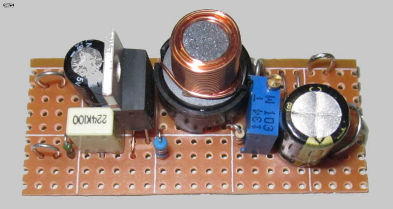
Figure 3 - 12V To +48V Converter Prototype
Yes, this is the exact same board as shown in Project 192, with the only difference being the feedback resistance. I tried using calculations and the datasheet charts, but in the end I used a 'pre-damaged' 330µH inductor with about half the turns removed before I could get 48V at the design current. The switching waveform was monitored up from the 'Switch' pin of the IC, and the other points of interest are also fairly easy to get to. I used a 10k trimpot to set the voltage because that gives plenty of range with a 33k series resistor. That provides enough adjustment range, even allowing for the IC's reference voltage being off (it's not exact, and varies from one IC to the next - 1.25V is the nominal reference voltage). The switching waveform is shown below, powered from 12V and with an output current of about 85mA. This circuit will work for any voltage from 12V up to about 60V (the maximum permissible for the LM2577).
Figure 4 - 12V To +48V Converter Switching Waveform
As you can see from the scope trace, the peak voltage is around 50V, and after the diode its 48V. The operating frequency measures a bit over 52kHz, which is the design frequency for the LM2577 IC, although it will vary slightly from one device to the next. There's some info on its range, including a graph of frequency vs. temperature. The frequency can be expected to be between 48kHz and 56kHz.
Even at an output current of close to 100mA it still performed well, and nothing gets even slightly warm (other than the load resistors!). Idle current is quite modest, and my power supply said it was just over 200mA while feeding an output load resistance of 1k (about 48mA). That's quite acceptable, and it's apparent that there's not enough current to heat up any of the parts. With no load, current consumption is about 16mA at 12V (just under 200mW), and 32mA at 5V (160mW), and if you only need to supply one or two mics it could even be run from a 9V battery. However, its life would be rather short - even at 100% efficiency it will draw 55mA from 9V, and 9V batteries only provide full capacity with a load of under 15mA.
With all boost converters, the input current is directly related to the output current, multiplied by the boost ratio. If the input voltage is boosted by four times, the input current must be four times the output current, plus the IC's operating current. With high loading there are additional losses that have to be compensated for by increased input current.
This project is designed specifically so that hobbyists can use an external 12V DC supply to generate a 48V phantom power supply, rather than using an AC wall transformer or having to mess with mains wiring. The design goal was to ensure that it has sufficient current for up to 10 phantom powered mics. Because nearly all external DC supplies are switchmode, adding more switching circuitry is unlikely to increase the audible noise level, but it would be unwise to use this without fairly extensive external filtering.
It's most certainly not the simplest way to achieve the end result, but it's fairly low cost, and is an interesting way for beginners to get used to switchmode circuitry, without having to resort to SMD parts. Be aware that the UC3845A is also available in SMD, so be careful when ordering. The inductor used is a fairly common value, and they are available in a fairly wide range of sizes. The DC component is quite low, so it doesn't have to be huge (although using a (physically) larger than optimal inductor won't hurt at all).
Because the power supply uses a commercial boost IC, you have the opportunity to examine the behaviour of the circuit, but with low voltages and no connection to the mains. Because it's fairly cost-effective, this is a simple way to obtain a P48 supply that can be powered from a normal 12V DC wall supply, or from 5V if you only need to run one or two mics. For anyone wanting to understand switchmode supplies, this is an invaluable learning tool, because you can attach a scope to any part of the circuit without risking life, limb or the scope itself.
Project 192 (ESP)
LM2577-ADJ SIMPLE SWITCHER® Datasheet
| Main Index
Projects Index
|