
|
| Elliott Sound Products | Transformerless Power Supplies |
 Main IndexArticles Index
 Transformerless power supplies have been shown in quite a few ESP articles, but for the most part without going into great detail. These supplies are inherently dangerous because they are directly connected to the mains supply. There is no isolation, so all powered circuitry is also at mains potential. This type of supply cannot be used for audio because there's no (sensible) way to provide inputs and outputs. However, they can be used for 'soft-start' (inrush limiting) circuits and anywhere else that requires a non-isolated power supply.
WARNING : The following circuits are not isolated from the mains and must never be used with any form of general purpose input or output connection. All circuitry must be considered to operate at the full mains potential, and must be insulated accordingly. No part of the circuit may be earthed via the mains safety earth or any other means. Do not work on the power supply or any connected circuitry while power is applied, as death or serious injury may result.
Under no circumstances should anyone who is not experienced with mains voltages attempt construction of a transformerless supply, as even a small error can be very dangerous. These supplies are potentially lethal, and great care is needed - always! By continuing, you accept all risk and hold ESP harmless for any death or injury suffered.
This class of power supply is covered briefly in the article Small, Low Current Power Supplies - Part 1 along with some appropriate warnings. There are examples, including one that was published some time ago that violated the wiring code of every country on the planet. Unfortunately it can still be found on the Net, and no doubt some people will still think it's a good idea (it's not!).
While these circuits can be useful, they have a limited range of applications. User accessible inputs and outputs aren't possible because they would be at mains potential, and even pots and/or rotary switches must have plastic shafts and plastic threaded bushes to ensure that they are properly insulated (the internal insulation is not rated for mains voltages). Even if you think you'll be the only person using the device powered with this type of supply, someone else will almost certainly be exposed to it at some stage. Remember that if you build a circuit that kills or injures someone, you will be held responsible!

Note: The AC mains nearly always has an active (aka 'live', 'hot' etc.) and a neutral conductor that's referenced to earth/ ground. However, supply authorities worldwide insist that the (supposedly 'safe') neutral conductor is considered to be live (at mains potential). It doesn't matter that you may only measure a maximum of a couple of volts on the neutral (referenced to 'true' earth potential), the neutral cannot (and must not) be considered to be safe. A miswired mains plug or socket, a dodgy extension lead or even old building wiring (installed before regulations were in place) can all reverse the active and neutral.
In some parts of the world, non-polarised mains plugs are common, and can be inserted into the receptacle either way, so 'live' and neutral are arbitrary! Please be very careful if you intend to experiment with this type of power supply. Make sure that you read and understand each and every warning provided in the text. If you don't understand the details, you don't have sufficient experience to build a transformerless power supply. Mains voltages are deadly, and I doubt that anyone wants to become a statistic.
There are non-isolated switchmode power supplies that can be considered to be 'transformerless', but this article only describes low-current capacitor-fed types. These are common in some appliances, as they save space and money (with the latter being the primary requirement in consumer products). The circuits shown are intended for low current, typically less than 50mA. If you need more than 50mA a transformerless design is not appropriate, and another approach is required (see Section 4).
The first stage of the design is to determine the requirements. The main thing you need to know is the current drawn by the circuit, as this determines just about everything else. A common need is to operate a relay, which can be controlled by any number of sensors. Remember that everything is at mains potential, and that extends to sensors, control switches/ buttons and indicators (e.g. LEDs, 7-segment displays, LCDs [liquid crystal displays], etc.).
If your design includes a relay, I recommend using one with a 24V DC coil. This reduces the current drawn (compared to a 12V relay) so the input current limiting capacitor can be smaller. The most common current limiter is a capacitor, which must be an X-Class type (most commonly X2). You may see circuitry elsewhere that uses a 400V DC cap, but these should never be used - especially with 230V mains. X-Class caps are designed to be 'self-healing', and won't fail short-circuit. DC caps have no guaranteed failure mechanism, and they can fail short-circuit. In some cases a resistor may be used to limit the current, but that may dissipate significant power.
In all of the following circuits I've included a MOV to minimise mains spike voltages that may damage C1. This must be the appropriate voltage for your mains supply, and will typically be 275V RMS for 230V mains or 140V RMS for 120V mains. MOVs have a limited life, and they can fail short-circuit, so fuse protection is essential. The MOV is optional.
There are some 'tricks' that can be used to minimise the overall current requirements, and these will be covered in more detail later. For the time being, we'll assume that you have some simple circuitry that controls a relay, which might just be a simple timer circuit such as that shown in Project 222 (a transformerless version of P39). There are always caveats with this type of supply, and you ignore them at your peril.
The arrangement you'll often see is shown below. In this and all following circuits, I've indicated a 'common' rail, not ground. No part of the circuit may be earthed/ grounded, as doing so risks a mains short-circuit. No part of these circuits is 'safe', and it's not possible to make them so.

This circuit is (usually) sub-optimal, as half of the available current is discarded because it's only a half-wave rectifier. Current to the load is provided by D2, and D1 just shorts the mains negative half-cycles to the common rail. Some circuitry demands a ½-wave rectifier though, for example if the 'common' has to include the incoming AC. The 'common' will preferably be the neutral, though in reality it makes no real difference.
By adding two more diodes, the circuit is full-wave, and the load can draw up to 12mA. It's still not very much, but it can power some simple circuits (including a relay with some trickery). The two 270k resistors bleed off any voltage that may be across C1 when power is removed. They contribute negligible current (less than 250µA at 230V AC), but should be not less than ½W to ensure their voltage rating isn't exceeded. You'll often see these resistors in parallel with the mains input. This works just as well, but the small current passed by the resistors is wasted. By having them in parallel with C1 means a few extra microamps are available for you to use.
R1 limits inrush current as C1 charges. Inrush is highest if the mains is turned on at the peak of the waveform. This peak current can be surprisingly large if R1 is omitted (greater than 50A is easy), and it can cause diode damage. The worst-case inrush current is just under 1.5A with 220Ω. A higher resistance limits that further, but may cause excessive dissipation. With an RMS current of 16mA, if you use 220Ω for R1 it will dissipate about 56mW.
The available current depends on two main factors - the mains voltage and the series capacitance. It's the capacitive reactance that is used to limit the current. Capacitive reactance is determined with the formula ...
XC = 1 / ( 2π F C ) so for 220nF at 50Hz it's ...
XC = 1 / ( 2π 50 x 220n ) = 14.47k
Ohm's law says that 230V with an impedance of 14.47k will pass 15.9mA RMS, not allowing for the series resistor and the output voltage. If half of that is discarded, the available current is (not surprisingly) half that which is passed by the capacitor. By using a full-wave (bridge) rectifier, we get more output current and it may be possible to reduce the value of C1. There are very few circuits that can't use a full-wave rectified voltage, but they do exist (for example in the ESP designed dimmer circuits shown in Project 157 and Project 159). The trailing-edge dimmer doesn't even use a capacitor - it uses a resistive current limiter (an uncommon choice, but necessary for that circuit).
The diodes are shown as 1N4004, but that's more for convenience than anything else. The reverse voltage is only around 14V for a 12V DC output. In theory you could use 1N4148 diodes, but the peak current can be up to 1.4A when power is applied, which may destroy the diode(s). The peak current is limited by R1.
R4 is shown as optional. It reduces the ripple on the 12V supply, but has little influence on the available current because the source (via C1) is a high impedance. Any value between 10Ω and 220Ω can be used, depending on the current needed. The voltage across C2 will be greater than the zener diode voltage if R4 is included. The zener will dissipate about 190mW, so it needs to be rated for 1W to ensure it doesn't overheat.
For both circuits shown, if your mains supply is 120V, 60Hz, the capacitance needs to be a bit less than double that shown (390nF will work because the frequency is higher). R1 can be halved and R3 omitted (shorted out), because the voltage is lower. With the Fig. 1.2 circuit, you will get a tiny bit more current at 120V vs. 230V (using 390nF for 120V).
The average DC output current is (approximately) 0.83 of the RMS input current. Since a 220nF cap can provide an RMS current of 15.8mA (RMS), expect a maximum DC output of ~13.9mA. In reality it will be a little less, depending on the DC output voltage. The DC output voltage reduces the voltage across C1, so for 24V output (for example) the peak voltage across C1 is reduced by 24V - a peak of ~300V rather than 325V. However, the RMS voltage is not proportional. Fortunately, you don't need to study these relationships in any detail, because the mains voltage varies anyway.
It's possible to get at least 50mA output current from the Fig. 1.2 circuit with no changes other than the size of C1. If C1 is 1µF (available with X2 capacitors), you can get 60mA easily, but R1 will have to be reduced to 100Ω or its dissipation will be too high. Everything is a trade-off, and remember that X-Class caps are designed to be self-healing, so every time there's an internal fault, the capacitance will be reduced a little. Eventually, you'll reach a point where the capacitance may only be half the rated value, and your circuit won't work any more (or it may 'misbehave' in new and exciting ways).
This loss of capacitance can prevent a relay from operating, but there are tricks that can be used to make it less critical. A 24V relay needs the full voltage to pull in reliably, but it only requires about 5-6V to remain energised. Any relay datasheet will provide the details for energising and de-energising, and the 'typical' drop-out voltage is 1/10th of the nominal voltage. A 24V relay will therefore only release when the voltage falls to 2.4V. Some relay datasheets show a 'must release' voltage.
If you plan wisely, you can ensure that you have plenty of voltage to activate the relay, and the voltage can then fall to less than half once the relay is energised. For this to work, the circuit must delay relay activation until the voltage has reached its maximum before it's turned on. In the Project 222 circuit, this is automatic, because the delay circuit is specifically designed to ensure that the relay has more than enough voltage to ensure reliable engagement before it's expected to operate. However, should the value of C1 fall far enough the relay won't pull in if other circuitry draws current too.
If your project uses a PIC or microcontroller, it would be wise to use an ADC input to monitor the relay supply voltage, and flag an error if it's too low. This will make later servicing a great deal easier, and only requires a couple of resistors and a bit of code. You'll also know the reason for the fault, as there's only one thing that can cause the voltage to be too low. Replacing C1 will restore normal operation.
If you work out the 'apparent power' (volt-amps) for the circuit, you'll find that with 15mA at 230V, it's 3.45VA, and that indicates a very poor power factor of about 0.15 (the ideal is unity!). However, unlike small switchmode supplies, the current is (more-or-less) sinusoidal with comparatively low distortion (only 21%). The power factor is leading (capacitive) which is a small problem for the grid, but users are charged for power and not VA.
Now you should be able to understand why these supplies are popular. The same result can be obtained using a resistor (for the 220nF version this would be about 15k for 230V input). Unfortunately, it would dissipate over 3.5W, and apart from the heat generated, that's power that you pay for. You'd need a 5W resistor, and it will run hot! A capacitive reactance dissipates no power, so it's a great deal cheaper to run. Depending on the specific application, you may find that this type of supply is not permitted under some regulations where the power factor is expected to be at least 0.9.
An example of a circuit using a relay to control mains (or other) voltages is shown next. This is deliberately configured to provide less than 24mA (for a 1kΩ relay coil). The voltage is clamped at 36V, and the control circuit draws 5mA. This can use a low-power regulator to obtain a stable operating voltage. A surprising number of circuits can be built that draw less than 5mA, so it's not a limitation. Higher current can be made available by changing C1 from 220nF to 470nF, which allows up to 25mA. Three 12V zener diodes have been shown, as a single 36V zener will dissipate over ½W (with 220nF) and it will run hot. By using three, each only dissipates 190mW. If a 470nF cap is used for C1, zener dissipation increases to 300mW each with no load. Keep the zeners away from C2, as electros don't like heat.

Fig 1.4 shows the sequence when powering a relay. C1 is 220nF, C2 is 220µF, and the relay coil is 1k. There's a load drawing ~5mA which represents a low-current control circuit. The first 850ms sees the voltage across C2 rise until it reaches 36V. At 3 seconds, the relay is activated, and it gets the full 36V when energised, falling to 10.6V as C2 discharges. The relay current is also shown. It reaches 35mA at the instant it's energised, and there's a holding current of 10.6mA. The nominal coil current is 24mA, and this is exceeded for over 120ms which guarantees that it will energise every time.
The only requirement for reliable relay activation is that it must not be re-energised until at least one second has elapsed after power-on or after it's de-energised. This allows C2 to charge to the full 36V again. Of course, it's not essential to allow 36V for a 24V relay coil - even 24V will be sufficient, but C2 would need to be a larger value (not less than 470µF). Project 222 shows an example of this general class of circuit. Even with a 100µF capacitor for C2, relay activation is absolutely reliable, but more capacitance is better. I've assumed a relay coil of 1kΩ, but you can get plenty of 24V relays with a lower coil current (a coil resistance of around 1.4kΩ is not uncommon), and this makes everything that much easier.
As an example, you may have a thermostat controlling a heating element. If the heated space temperature is less than the preset value, the circuitry would normally try to turn on the relay as soon as power is applied. This won't work, because there will never be enough voltage for the relay to activate. A 24V relay will typically require at least 18V to pull in, and if it's connected to the supply at start-up, there will never be enough voltage available as it can only reach ~10.6V with the relay connected. The simple answer is to design the control circuit so that there's a delay of a few seconds after power-on before the relay is activated.
This approach will ensure that the circuit functions normally, and if you design it well, it will continue to function normally even after C1 has been degraded. The circuit shown in Fig 1.3 will still work if C1 is reduced to 100nF. The relay will only have a continuous voltage of around 4.4V, but that's comfortably higher than the ~2.4V required by a 'typical' 24V relay. The control circuit also has to remain functional with the dramatically reduced voltage, and that might be a challenge.
The idea of powering relays with a higher than normal voltage and then allowing the voltage to fall once it's energised is often called an 'efficiency' circuit, as it reduces the relay coil dissipation when the relay is on. A relay with a 1kΩ coil will dissipate 576mW at 24V, but only 144mW at 12V. Every saving is worthwhile, but it's probably a moot point for a heater (for example) which may use 1-2kW in operation. The complete circuit as shown will dissipate a little over 420mW whether it's powering a relay or not, where a small switchmode power supply may draw less than 100mW when idle.
You may choose to use a TRIAC with a TRIAC optocoupler (e.g. MOC3020 or similar) rather than powering an electromechanical relay. The optocoupler's LED typically needs 10mA for reliable triggering, but of course the TRIAC will dissipate power too (typically 1 to 1.5W/ A), and it will need a heatsink for high current. This can easily negate any savings you may make with the supply itself. Using a 'hot' heatsink (i.e. at mains potential) is dangerous and strongly discouraged.
If your project uses a relay, a 24V type is always a better choice than anything with a lower coil voltage. There's a lot to be said for letting the relay supply go above the nominal coil voltage, as that ensures a rapid turn-on and minimises possible contact damage. As shown in Project 222, a supply voltage of 36V is not a problem for the relay, and the voltage can fall to as low as 5V once it's energised. Of course, any additional circuitry you include has to be able to work with the reduced voltage too, and the current drawn by the circuit has to be accounted for.
While the supplies shown have a positive output, it can be negative if that's more convenient. The easy way to do that is to classify the 'output' as common, and the 'common' terminal is then the output. You can also have multiple voltages, such as ±12V. This is achieved simply by using two 12V zener diodes in series, and using the centre-tap as your 'common' connection. Since this class of supply cannot (and must not) be referenced to earth/ ground, the output polarities are arbitrary. They are determined by your application.
For example, to get ±5V, the Fig 3.1 circuit is all that's needed. It can supply up to 28mA, and if you need a higher voltage (e.g. ±12V) then it's just a matter of swapping out the 5.1V zener diodes for 12V. The current is reduced a little, but you can still get 27mA at ±12V. However, this is with the nominal 230V supply, and you must consider that the mains voltage can vary by up to ±10%. The available current changes accordingly, so you should never expect to get the full (theoretical) output current. It's a good idea to allow somewhere between 10% and 20% safety margin, so if the maximum is (say) 25mA, you should draw no more than 20mA. More is alright if regulation isn't essential.
The two outputs can just as easily be +5V and +10V, or any other voltages that might be used with a simple controller and a relay (which could also be a solid-state type [SSR] for reduced current draw). Most SSRs need around 10mA input, but they cannot be used with an 'efficiency circuit'.
You can get more current by increasing the value of C1, or less by decreasing it. A pair of 470nF caps in parallel will let you draw up to 50mA, and that's more than enough for many 'typical' applications. The most important thing is to ensure that the relay is never expected to turn on at the same time as power is applied.
Transformerless supplies are designed for low-current applications. That means no more than around 50mA in most cases, otherwise the circuit can no longer satisfy the criteria for 'low power'. Essentially we're looking at a PSU and load dissipation of perhaps 1W, and usually less. 1W allows up to 80mA at 12V, but you can get more power at higher voltages. If you have a 24V supply, it's quite easy to get up to 2W without having to use a stupidly large cap for C1. Don't try to use low-voltage relays, as they draw more current than with higher voltages. 24V is recommended if possible.
It wouldn't be sensible to try to run (for example) an Arduino or similar from a transformerless supply, as they may draw up to 500mA and the value of C1 would be excessive. You'd need at least 7µF (use 10µF), rated for mains voltage. It would require an NTC thermistor instead of R1, or inrush current would cause major problems. Even when used with 'sensible' capacitance (220-470nF) inrush current is surprisingly high. It's limited only by the series resistor (R1).
Anything that uses external sensors and involves plugs and sockets is very risky and must be avoided. There are few connectors (other than mains input/ output connectors) that are rated for mains voltages, so this is often a major limitation. Likewise, don't expect to be able to connect any external device - a laptop for example. Suitable connectors don't exist, and the entire laptop would be at mains potential. The risk is obvious, and the result could be fatal.
While a transformerless supply may seem attractive, you can use a small (~12W) 'plug-pack' style supply. Once removed from its original housing, it can be relocated inside a small utility/ jiffy box, or you could 3-D print one if you like. The output is isolated to the full mains voltage, and is as safe as possible. Naturally, the supply you use must have full approvals for sale where you live. See the article Dangerous Or Safe? - Plug-Packs (aka 'Wall Warts') Examined. This explains why proper approvals are so important.
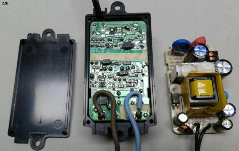
The one pictured above is a very good example. The supply is well designed and made, and is a perfect fit inside the small enclosure. In some cases, you may be able to pop the case apart and saw off the AC pins (and any other un-necessary protrusions) and re-use the original enclosure. Naturally, it will be used inside the main enclosure for the project it's powering, and all mains wiring will be preformed to a high standard.
The supply shown has a 12V, 1A output, and is regulated. When used as an alternative to a transformerless supply it will probably be idling most of the time, and no-load losses will be negligible with an approved supply. Most will be designed to meet the requirements for less than 500mW idle power, with 'better' ones using no more than 100mW with no load (some are much less). The SMPS pictured only uses 90mW (230V) with no load. If well designed, the expected life is probably similar to that of a transformerless supply, and it means that you can work on the electronics without fear of electric shock.
The other alternative is (hopefully) the most obvious - use a mains step down transformer. By default these are fully isolated for mains voltage use, and a transformer is by far the safest option. Small 50/60Hz transformers that can deliver 12V AC can be as small as 33 x 28 x 30mm (2.3VA, 190mA AC @ 12V AC output) and they are relatively inexpensive. Many are inherently short-circuit proof, and you can get around 120mA DC from the example mentioned. You have to add a bridge rectifier, filter cap and optionally a regulator so the PCB real estate is increased. However, it is the safest option of all, and it will have the longest life.
Simple timers, thermostats and other useful functions can all operate within the 2W limit if suitably low-power circuitry is employed. Great care is always necessary to ensure that no part of the supply or the powered electronics can be accessed by the user, since everything is at mains voltage. Connectors are an absolute no-no unless they are mains rated, and external sensors, potentiometers, switches and wiring must also be rated for the full mains voltage.
Be warned that there are several projects that you'll find on the Net that are likely to be lethal if used. Not only lethal for the user, but also for an oscilloscope or other test equipment that may be connected. Any transformerless supply that provides access to the DC output is a killer, just waiting for some hapless soul who thinks it's a 'good idea'. Unfortunately, the Net provides access for complete idiots to publish whatever they like without caring (or perhaps even knowing) about the possible consequences.
It's possible to get a great deal of functionality with low-current electronics. Many PIC microcontrollers draw less than 10mA in operation, allowing a lot of computing power. As already noted though, inputs and outputs remain a serious challenge. In general, the electronics should be completely 'self-contained' within the enclosure. How this is arranged depends on the application. Always be aware of power dissipation in resistors and (especially) zener diodes. This is especially true if the enclosure is plastic and sealed, because heat can't escape easily.
Using mains cable for a sensor (for example) is unwieldy but essential, and many of the small switches that one would normally use on simple electronic circuits are not safe when the electronics behind them is at mains potential. Manufacturers may get around that by using a membrane as an insulation barrier with the switches behind it. If you have any doubts about the suitability of this type of supply, I suggest that you use a small flyback SMPS (a plug-pack, aka 'wall wart'). Once your electronics are isolated from the mains, everything gets a great deal easier.
The reactive component of choice for this kind of supply is always a capacitor. An resistor could be used, but it will dissipate significant power and run hot. You will pay for the wasted power too, making it an unattractive proposition. You could use an inductor, but it will be much larger and more expensive than a capacitor. I've never see that as an option. I mention this only because it's possible, but it's definitely not practical.
Overall, an approved plug-pack SMPS is always a better choice, and the extra cost is easily justified for DIY. You may only need to build one unit, so a bit of extra cost to buy safety isn't a major hit to your 'bottom line'. Ultimately you have to decide how much your life is worth!
There are no external references, only other ESP articles. These can be found in the articles index.
Main IndexArticles Index