

|
| Elliott Sound Products | VCA Techniques |
 Main Index
 Articles Index
A VCA (voltage controlled amplifier/ attenuator) is the heart of any compressor or peak limiter circuit, and there are quite a few different approaches. All available circuits have limitations, and this article looks at the various techniques used. VCAs are also used to provide mixing desk automation, noise gates, 'de-essers' (sibilance reduction), duckers (that automatically reduce background music when someone speaks into a microphone), in synthesisers and even as volume controls. They were also at the heart of many early noise reduction systems, such as those used by Dolby (over several generations of noise reduction systems), as well as simpler 'level dependent filters' that were once fairly common in consumer applications.
The most difficult problems to solve are distortion, control voltage feedthrough and tracking from one unit to the next. The latter is only important for volume controls and multi-channel compressors, where the relative channel-channel balance must be preserved. Tracking is also important for noise reduction and other 'companding' applications, because expansion has to be exactly complementary to compression to restore the original dynamic range.
Distortion is always important, but tracking only becomes an issue with stereo compressor/ limiters or expanders (aka expandors), where the relative levels of left and right (or multiple) channels must be maintained within close limits. For a stand-alone compressor/limiter that only processes one signal, tracking and gain vs. control voltage accuracy are largely irrelevant. The degree of compression will more likely be set by ear than by numbers on a dial.
Another issue faced is control voltage 'feedthrough', where the CV (control voltage) signal causes a momentary DC level shift on the signal. This becomes particularly important when a very fast attack time is used, because the control voltage changes quickly enough to cause an audible disturbance. No usable compressor/limiter can have any significant feed-through, as this is typically more objectionable than a bit of distortion.
When used as compressor/ limiters, the VCA's side-chain is configured to provide adjustable time between the arrival of a high-level signal (attack), and how long it takes for the gain to be restored to normal (decay or release). In synthesisers, a common set of adjustments provide the 'ADSR' functions ... attack, decay, sustain and release. These controls are used to shape the waveform produced to get a wide range of different sounds.
A search of the Net will uncover a great many different types of compressors and limiters. Some are original schematics of some of the best known units around, some are (or appear to be) a work-in-progress, while others are best described as abortions of the highest order. There is no single technology that will suit everyone, and as always with anything audio there are some that are claimed to be 'magic'. Many of the early units used light dependent resistors (LDRs, with electro-luminescent panels for illumination), some have used diodes, and many examples of FET controlled systems are to be found.
| Technology | Distortion | CV Feed-Thru | Speed (Attack/ Release) |
| 'True' VCA | low | low * | fast |
| Analogue Multipliers | low/ medium * | low * | fast |
| LTP Transistors | medium/ high | low * | fast |
| OTA | high | medium/ low | fast |
| LED/ LDR | low | nil | slow/ medium |
| JFET | high | medium/ nil # | fast ** |
| Diodes | high | high * | fast ** |
| PWM | low | nil | fast |
| Digital | All functions depend on implementation and DSP used | ||
| Variable Mu | low/ medium * | low/ medium * | medium ** |
| * usually adjustable using preset pots |
| # depends on speed and circuit topology |
| ** speed depends on implementation and topology |
This is an extensive list, but it still has to be considered as very generalised. It covers the most important parameters of any compressor/ limiter, noise gate, etc. Different attributes will appeal to different users, and relatively high distortion may be considered an asset by some while others will look for the lowest distortion possible. CV feed-through is unlikely to appeal to anyone, and speed is entirely dependent on how the unit is used. Relatively low speed may not be an issue for example, depending on the source material and how the compressor/ limiter is used.

| It's very important to note here that contrary to popular belief, a compressor will not save loudspeakers from damage with high powered amps. In fact, the reverse is true, because a compressor causes the signal to have a higher average voltage (and hence higher average power) at the onset of amplifier clipping. If you wish to protect speakers, a peak limiter with reasonably fast attack and slow release is needed. If set up properly, a limiter will maintain the dynamics and therefore (hopefully) keep the average power down to a sensible level. It ensures that the peak power cannot exceed the preset limit, other than fast transients which may cause the amp to clip briefly. Again, contrary to popular belief, this will not cause the speakers to fail, as long as the continuous average power is within the speaker's ratings. There are other factors as well, but they are outside the scope of this article. See the Speaker Failure article for more. |
This discussion does not include the side-chain ... the rectifier, attack and release circuits, RMS detector and any other control voltage processing (Figure 13.1 excepted). Ultimately, the performance of any compressor/ limiter is determined first and foremost by the gain control system. Everything else is secondary, and the best side-chain in the world won't save a crappy gain control element. On the other side, the best VCA on the planet will be let down by a side-chain that isn't up to scratch. The rectifier should always be full-wave, and for a 'proper' compressor the detector should be a true RMS type, but also switchable for peak detecting as well.
The side-chain is probably worthy of an article unto itself, but that's probably for some time in the future. Side-chain processing can be extensive, with often a great many options. It's not unusual to include (or include the ability to add it if needed) equalisation of the signal sent to the side-chain, so you can get different compression or limiting characteristics depending on frequency.
Something that seems to puzzle beginners is the difference between a (peak) limiter and a compressor. A limiter is literally just that - it limits the maximum peak level to the preset value - say 0dBV for example. The threshold is usually variable, so you can set the maximum output level to suit the equipment being driven. Provided the peak amplitude of the input signal remains below 0dBV, nothing happens, and the signal passes straight through without alteration. If the input level exceeds 0dBV, the limiter reduces the gain so that the output remains at the preset level. In theory, it doesn't matter how much input signal you apply, the output peaks can never exceed 0dBV. In reality, there will always be an upper limit, because the source (mixing console, preamp, etc.) doesn't have infinite headroom, and nor does the control element. The compression ratio of peak limiters is usually 20:1 or more - the input signal has to be increased by 20dB to get a 1dB increase at the output.
A compressor is rather different, and there are also different compression techniques that are used. In essence, a compressor literally compresses the dynamic range. If the input signal has a dynamic range of 60dB, a compressor set for 2:1 compression will reduce that to 30dB, or if set for a ratio of 3:1 it will be reduced to 20dB. When the compressor is used with fast attack and release times, all dynamics are squashed, and the output lacks normal variation. There are additional complications in most compressors though ...
It's common for compressors to have a threshold adjustment, and that means that any signal that's below the threshold is not affected. Only when the signal level exceeds the threshold will it be compressed. As before, the ratio can be set, and compression is generally classified as having a ratio of 2:1 up to perhaps 5:1 - above that it functions more like a limiter. For dynamic range compression, the detector/ rectifier should be a true RMS type, although many use a simple peak or average detector because it's easier and cheaper. However, peak detection for a compressor is less accurate for a music signal. Average detection is usually alright in practice, and true RMS adds expense so isn't as common as it probably should be.
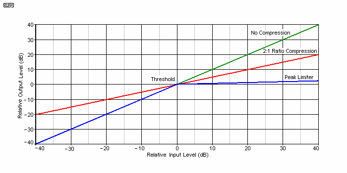
In the above, you can see the behaviour of a compressor (blue below threshold, red above) and a peak limiter (blue). The red trace is a special case - it shows full dynamic range compression, where low level signals are amplified with more gain applied as the level reduces. Above the set-point, gain is reduced as the level increases. Note that at extremely low levels, the gain is not infinite - there is always a point where the gain reaches a preset maximum, and anything below that is effectively lost.
The blue/red trace shows a typical compressor setup, where there is no compression below the threshold, and the level is compressed once it exceeds the threshold. Although the graph only shows 2:1 compression, in reality it can be set lower or higher depending on the abilities of the compressor.
The red trace shows the only form of compression that can be successfully reversed (by an expander/ aka expandor) to restore the original dynamic range. This technique was used in Dolby noise reduction systems to minimise tape hiss when cassette recorders were part of almost every hi-if system. These systems also included pre-emphasis (high-frequency boost before compression) and de-emphasis after compression to restore the original high-frequency response.
A good example of a 'compandor' (compressor/ expander) is the SA/NE570/571. These ICs were introduced by Philips (now NXP) in the 1970s, and are specifically designed for complementary compression and expansion. While they can also be used as VCAs, performance is somewhat mediocre. The variable gain cell is (according to the data sheet) a linearised two-quadrant transconductance multiplier (see Long-Tailed-Pair Transistors below). Although the datasheet claims a trimmed THD of 0.05%, in my experience this is extremely optimistic. The IC is also let down rather badly by the internal opamp (which is no better than a µA741), although it's possible to use an external opamp instead.
Note that all diagrams shown in this article are fairly basic - these are not construction projects, and component values (where provided) are representative, and/or were used for simulations to test that the circuits actually function. Of these, only the FET, diode and LED/LDR circuits were bench tested. All others were simulated.
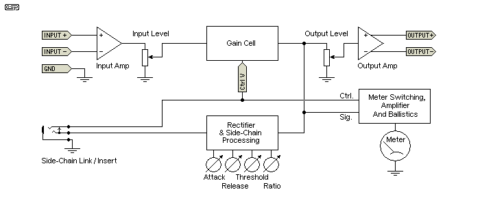
The above drawing shows the general form of a compressor or limiter. The inputs may be balanced or unbalanced depending on intended usage, and the available controls depend on the unit's design. Some provide access to the side-chain (the rectifier and control voltage (CV) circuitry), others may use a micro-controller to set up various parameters. Many units allow a single meter to be used to monitor the input, output and gain reduction, selected by front panel switches. The term 'ballistics' refers to the way the pointer (or other indicator such as LED arrays) moves in relation to the applied signal - VU, PPM, or proprietary/ undefined.
The rectifier is really the heart of a compressor/ limiter. To be useful, it must be full wave. A half-wave rectifier can only look at leaks of one polarity, and this can cause large errors with asymmetrical waveforms. For compressors, the better units use an RMS (root mean square) detector that uses the RMS voltage of the input waveform rather than the peak. Peak limiters should obviously use peak detection - an RMS detecting peak limiter doesn't make sense and is an engineering oxymoron. Other than the obvious input and output level controls, other typical controls are ...
Attack sets the speed for compression/ limiting to occur when a signal exceeds the threshold. Typically between 0.5ms to 100ms Release how quickly gain returns to normal after signal goes below threshold. Slow release helps prevent excessive dynamic range compression & reduces audible artifacts Ratio lets the user select various amounts of compression. When set to maximum the ratio is usually 20:1 or more and the unit acts as a peak limiter Threshold sets the level at which compression or limiting occurs (refer to Figure 1.1)
Not all compressor/ limiters have all controls. In some cases, the threshold is set by adjusting the input level, in others, an 'automatic' mode is available where attack and release times are determined by the programme material rather than control knobs. In reality, this tends to happen anyway, because a high-level transient will almost always cause the circuit to have a faster attack than a low-level transient. Some limiters and compressors are rated for an attack and release time based on the amount of gain reduction in dB.
It's also common for compressors, expanders and limiters to allow linking, where two or more gain control systems share the same control voltage. The CV is often derived from both channels, summed, and used to control the VCAs of both channels at once. This allows the units to work with a stereo or multi-channel signal while maintaining the balance between the channels. In some cases, the control voltage output from one compressor/ limiter may be used to control others, by breaking the side chain loop. There are many variations, and that shown in the above block diagram is just one possibility.
Where an 'insert' facility is provided, it seems to be more common for it be in the AC part of the side chain (before the rectifier). Also, many commercial compressors use an AC 'link' rather than the DC link shown in Figure 1.2. As already noted, Figure 1.2 is simply an example, and doesn't represent any particular compressor.
The most common use for compressors is to ruin the sound. They are used extensively with most modern recordings, often with the signal being peak limited, then compressed several times. Everything sounds the same volume, so a solo acoustic guitar is exactly as loud as the whole band at full tilt, a whisper is as loud as a shout, or for movies (as usually broadcast on free-to-air TV), a pin dropping is at almost the same volume as a gunshot. It is obvious that some compression is needed for a movie soundtrack, but it should be the minimum possible while still allowing for a sensible dynamic range so that loud things are loud but dialogue is still audible.
One TV station in Australia uses so much compression during news broadcasts that one can easily hear the compression artifacts - commonly known as 'pumping' or 'breathing'. Despite the fact that their news is far better than most other channels, I find it extremely painful to listen to because I hear the compressors and limiters working furiously to ensure that every sound is the same volume as every other sound or noise. When one has worked in audio for many years it's hard to ignore obvious glaring flaws in sound quality.
This is a common complaint, and some 'mastering' studios (I prefer the term 'mangling' studios) try their hardest to reduce the dynamic range to the absolute minimum possible. This is covered in the ESP article Compression In Audio Recordings, and is also complained about very loudly on the Net. Unfortunately, the mangling studios aren't listening, and they continue to ruin everything that comes their way.
The pumping/ breathing effect referred to is occasionally considered a viable sound effect, but mostly it's something to be avoided. Fast release times are the main cause, made worse if the attack time is also fast.
In addition, fast attack and release cause low frequency distortion as the cycle time of the low frequency approaches the compression/ limiting time constant. For example, a 40Hz note has a cycle (periodic) time of 25ms, and the release time of the compressor/ limiter should be at least 10 times that to avoid gross distortion. If low distortion is desired at all frequencies then the release time probably needs to be at least a couple of seconds.
It should be understood that compression is often used very delicately by recording engineers, who are often looking for subtle changes to the 'character' of the sound. Not everyone uses it to 'flatten' the dynamics so everything is at the same volume, and some individual tracks may only be subjected to a few dB (1-3dB for example) to enhance the sound of the instrument, or to keep the level of individual notes more even (some instruments - particularly acoustic bass/ guitar - may have a natural tendency to make some notes louder than others). All compressor systems tend to have a particular 'sound', either by adding a small amount of distortion, colouration of the frequency spectrum, or their response to transients.
It's not at all unusual to find a recording studio with several different compressors, both hardware and software, with the latter in 'DAW' (digital audio workstation) systems. The recording engineer may choose one compressor for bass guitar, another for drums, and a different one for vocals. The studio monitoring system needs to be very high resolution to hear the difference, but it will always be there. No two compressors will sound exactly the same, but some will be very close. What excites a recording engineer will often go completely un-noticed by the listening public.
Back in the early 1970s, dbx ® co-founder David Blackmer designed the first true VCA that had good performance over a wide gain range. The log-antilog core is the heart of the circuit, and it requires closely matched transistors and diode-connected transistors (shown as diodes below) with excellent thermal tracking. It is now produced by THAT Corporation as a fully integrated component. The 2180 series have claimed distortion of between 0.01% to 0.05%, depending on the part number suffix.
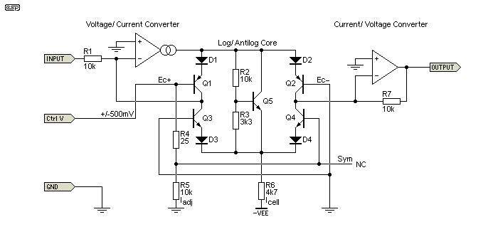
It seems to be accepted (based on comments in forum sites) that trying to build the Blackmer circuit using discrete parts is likely to result in the constructor giving up in disgust well before s/he ever gets it working properly. However dbx used to do just that in the early years. I've not tried to build one, but was able to get a very passable simulation working. The circuit shown above is based on the simulation I ran. The CV input is limited to ±500mV or so, and the signal output change is roughly 6mV/dB - the output change is logarithmic for a linear control voltage input.
The Blackmer cell requires an input signal current, not voltage. The output signal is also a current, and needs an opamp connected as a current-voltage converter to develop the required output voltage. A similar topology was used by Valley International (formerly Allison Research then Valley People). The Valley log-antilog cell performs in a somewhat similar manner to the Blackmer cell, but is normally operated in Class-A (rather than Class-AB for the Blackmer cell). While this may be seen as a significant advantage for minimal distortion, the Blackmer cell has remained and is still available (THAT2180 series). Quoted maximum distortion for the THAT2180A (the 'premium' version) is quoted as being less than 0.01%. They are readily available from several suppliers, and are in a SIP (single inline pin) package.
Meanwhile the Valley design seems to have vanished - it might be available somewhere, but I found no evidence of it in my searches. The fact that the Valley VCA required a significant number of external parts would have reduced its appeal dramatically. The only circuitry integrated into the IC was the log-antilog core, with everything else being external. This may give greater flexibility, but at the cost of PCB real-estate and increased manufacturing cost.
Note that the diagram and description are intentionally fairly basic. This is not an article about Blackmer cells (or log-antilog cells in general), and the diagram is deliberately rather sparse. It's adapted from the THAT2180 data sheet, and is intended to show the basic form of the device - not a detailed description. Figure 3.1 shows the circuit exactly as I simulated it, and while not perfect it does simulate quite well.
There's a trap for the unwary with VCA chips, and that's control voltage noise. For example the THAT2180 has a CV sensitivity of 6mV/dB, so if there's 1mV of noise (or perhaps a significant amount of ripple for a compressor/ limiter) on the control signal you'll get 0.16dB of noise modulation in the controlled audio signal. Any ripple after the control voltage rectifier will cause signal distortion, and this will typically be far greater than the distortion contributed by the IC by itself. To minimise control voltage ripple and therefore distortion, the attack time can be moderately fast, but release should be fairly slow. This limitation actually applies to almost all compressor/ limiters, regardless of the type of VCA.
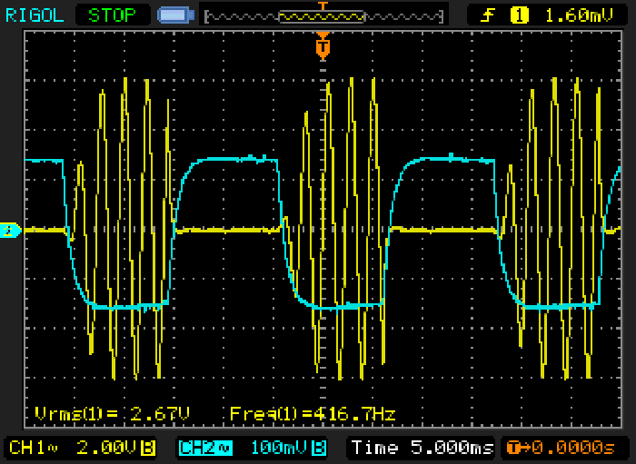
This is one of only three oscilloscope waveform captures I did for this article, and all other variations (with the possible exception of the PWM version shown below) will normally be worse. The yellow trace is the signal (input is around 440Hz at 1V RMS), and it's modulated with a 40Hz, ±150mV peak squarewave. There is no evidence of control voltage on the signal, and you can see that the signal follows the CV almost exactly. I tested this with an AC control voltage up to a couple of hundred Hertz - it sounded awful but the modulation was perfect, with no feedthrough. The modulation signal is a rounded squarewave because of a control voltage decoupling cap. This is essential to minimise modulation noise (remember that the gain varies by 1dB for a CV change of only 6mV).
In case anyone is thinking that the THAT2180 could be used as an AM broadcast modulator, the answer is 'no', because the control voltage action is logarithmic, not linear. In addition, the audio path is not suitable for RF as its frequency response is limited to around 100kHz.
Analogue multipliers (e.g. MC1594, AD834, AD633, etc.) can also be used as VCAs. Analogue multipliers come as single quadrant (inputs and output are all the same polarity), 2 quadrant (one input is unipolar), and 4 quadrant (inputs and output can be positive or negative). To be able to process analogue signals properly and with minimum distortion, 2 or 4 quadrant multipliers are required. Some of these devices are extremely expensive ... even 'cheap' analogue multipliers are comparatively expensive.
In reality, the 'true' VCA is a 2 or 4-quadrant analogue multiplier, but is specifically designed for audio use. While general purpose analogue multiplier ICs are reasonably well suited to VCA use, it's better to use a dedicated ('real') VCA rather than throw a fairly expensive IC at the problem, when the purpose designed VCA is roughly the same price or, in most cases, cheaper.
Most of the once common analogue multiplier ICs are now obsolete, but the AD633 is still readily available. These are internally trimmed when manufactured, and should perform very well. Noise is not wonderful (it's quoted in µV/√Hz, where opamps are in nV/√Hz), so the AD633 should be used at a relatively high level (a signal input of no less than 1V RMS and a control input of 0-10V DC) so that the noise is minimised. The 'Y' inputs (for reasons that are not explained in the datasheet) have better linearity than the 'X' inputs, so the signal should always be connected to a 'Y' input, and the control voltage to an 'X' input. Unused inputs can simply be returned to earth/ ground.
As of 2023 (the last time I checked), the cheapest versions of these ICs are over AU$25 each (for the SMD version), so it's not a low-cost part (through-hole versions are more expensive than SMD). Voltage control is linear, so (for example) with a control voltage of 1V and a signal voltage of 1V, the output is 1V x 1V / 10 = 100mV, as the product is divided by 10 internally. With the control voltage at zero, the output is also zero. Noise on the control voltage will modulate the output signal in direct ratio to its magnitude and that of the signal. Remember that the IC is a multiplier, and the two inputs are simply multiplied together. If you apply a negative control voltage, it causes the signal to be inverted.
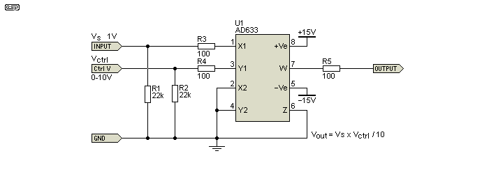
As a true multiplier, the AD633 (and other similar devices) are dead easy to use. Apply a signal (around 1V RMS is good) to the 'X' input, and a 1-10V control voltage to the 'Y' input. With a 10V control voltage, the output is 1V, and with 0V control the output is zero. The AD633 is factory trimmed, and offset is generally very low. To obtain maximum attenuation (close to ∞), you may need to trim the control voltage a few millivolts one way or the other. A negative control voltage will give you signal again, but inverted. The only things missing from the drawing are the supply bypass caps, but otherwise everything you need is done by the IC. Either input ('X' or 'Y') can be differential (balanced) if preferred.
Although extremely capable and able to give very good performance, the AD633 is more expensive than many 'true' VCAs. However, it can be used to do things that most VCAs cannot, such as providing almost perfect amplitude modulation, and very linear control characteristics. However, the key word here is linear, so it's not really suitable for multi-channel volume control unless the control voltage is logarithmic.
The AD633 datasheet shows an application circuit for an AGC (automatic gain control) system, with true RMS detection. While not a cheap circuit to build (RMS to DC converter ICs are also expensive), it would no doubt work very well in practice. The control voltage must be reduced to lower the circuit gain, and sensitivity to control voltage ripple (from the rectified signal) is quite high, so very good filtering is necessary. If you wish to play with these devices, read the datasheet and any other literature you can find. There's a lot more to analogue multipliers than the basics described here.
Like the VCAs described in the following section, analogue multipliers generally use long-tailed pairs as the controlled gain element. This means that they too rely heavily on the current sources, sinks and mirrors referred to next. The main difference is that they don't use logarithmic control because they are true multipliers, so the two inputs are linear. In case you're wondering why the output is divided by 10 internally, it's to allow input voltages of up to 10V to be accommodated. The with two inputs at 5V (for example) the output will be 2.5V which can be provided by the supply rails, as opposed to 25V which cannot.
The following two circuits rely on current mirrors and/ or current sources/ sinks. Rather than explain these in detail here, please see the article Current Sources, Sinks & Mirrors which has detailed explanations of this class of circuit block. Without having a basic idea of what they do (and why), you'll be unable to understand the circuits at all.
Current mirrors are used extensively in IC design, because it's very easy to make transistors but difficult to fabricate decent resistors in silicon. Current mirrors are such a fundamental building block in IC design that it's important to understand that many of the ICs we take for granted today could not even exist without them.
Long-tailed pairs (LTP) are also used as VCA blocks. In some cases the 'tail' current is varied to change the gain, and in other variants the input signal is applied to the 'tail' and the control signal is applied to the transistor base(s). SSM (Solid State Microtechnology/ Solid State Music Technology/ Solid State Technology for Music/ Analog Devices) made the (now obsolete) SSM2014 which used the latter technique, but the SSM2018 is still current. In reality, the SSM2014/8 is something of a hybrid, which uses a LTP circuit as a transconductance amplifier, but adds log-antilog functionality as well. Distortion is not quite as low as the premium THAT2180A, but is still very respectable at around 0.015% (for frequencies below ~3kHz). There is also a quad version, the SSM2164. It has slightly higher distortion than the SSM2018 but is much cheaper per VCA than any of the other high quality types.
The devices used for the LTP can be bipolar transistors, junction FETs or even variable mu triodes. In the version below, BJTs are shown (changed from JFETs), but the same basic circuit works equally well (or badly, depending on your expectations) with JFETs or even triode valves. It's (somewhat) easier to get high linearity with BJTs than JFETs, but the input voltage has to be limited. In general, the input voltage for any LTP circuit will be no more than 20mV or so, or distortion will be much higher than you'd prefer. The choice of JFET will influence results (usually dramatically), and finding suitable devices is no longer simple as so many have been discontinued.
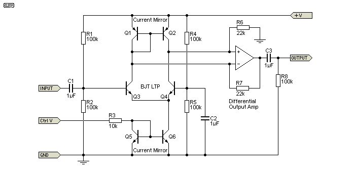
This same technique is used with OTAs as well as purpose-designed audio VCAs, so is far more common than you might imagine. There are countless different tricks used in this type of VCA, all of which are intended to reduce distortion and control voltage feed-through. Each manufacturer uses (or seems to use) different methods, presumably to get around patents held by others. It's shown using BJTs, which generally perform a little better than JFETs - see Project 213, a DIY voltage controlled amplifier that actually performs a great deal better than I expected.
While it is certainly possible to get excellent performance from this type of circuit, it requires very close matching and typically laser trimming to obtain performance that is good enough for professional or hi-if use. For music instruments (as a guitar effects pedal or as part of a synthesiser for example), any distortion or colouration that the IC contributes becomes part of the sound. Guitarists may have two or more compressor/ limiters, and they will use the one that gives them the sound they want. The same applies for studio use, where the producer might have numerous units available, and can choose the one that gives the desired effect for the instrument being recorded or mixed.
The OTA or Operational Transconductance Amplifier is also a commonly used VCA, despite relatively poor overall performance. These devices use a long-tailed-pair as the control element, and there are usually 'linearising' diodes added to try to minimise distortion. Most OTA devices are now considered obsolete, such as the CA3080 and CA3280. The LM13700 is still available, as is the NE5517, but neither can approach dedicated audio parts such as those by SSM (now part of Analog Devices) or THAT Corp. Output is current, not voltage. For undemanding applications it's been common for designers to use a resistor as the 'current to voltage converter'. While a resistor is actually an extremely linear way to convert current to voltage, that doesn't apply with devices like the 3080 or its successors, because output current is most linear if the voltage remains constant (nominally zero).
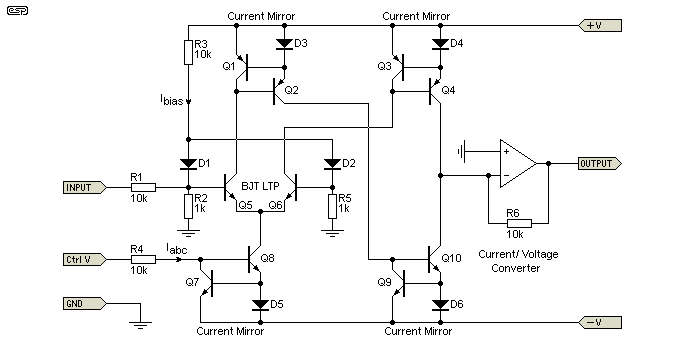
D1 and D2 are the linearising diodes, and Ibias is the forward biasing current. Iabc is the control current. Almost the entire OTA circuit is made up of current mirrors, with the exception of the long-tailed-pair. The underlying similarity between this circuit and Figure 5.1 should be apparent - both rely on a LTP to function. The opamp shown is external - it converts the output current to a voltage.
There are quite a few OTA compressor circuits to be found on the Net. I've never found the OTAs I've used to be very impressive ... they work well enough, but overall distortion is higher than I consider desirable. While a FET based attenuator may have (say) 0.5% THD, that's the worst case, where the voltage across the FET is fairly high. If used at a lower threshold voltage distortion can be kept well below 0.1%. With an OTA, there is some distortion at all levels, and you can't make it go away.
One of the earliest (and it's still a very competent combination) is to use an LDR (light dependent resistor) along with a fast light source. Before LEDs, small filament lamps were used, and some early commercial products used an electro luminescent panel to generate light (The Urei LA-2 and LA-3A are good examples). These are much faster than lamps, but require a high voltage to generate any useful light. LED/LDR combinations (e.g. Vactrol or home-made) are very good, having commendably low distortion. However, LDRs are inherently slow so fast attack times are not possible. Despite this, for normal full range music they generally sound just about right. You cannot use a LED/LDR limiter with sharp, percussive sounds though, as the inherent low speed makes the device perform more like an expander!
As a VCA, they are pretty pointless because of very poor tracking from one to the next. It would certainly be possible to match the LEDs and LDRs to get passable tracking, but it would not be very trustworthy as there are likely to be significant characteristic changes with both time and temperature. Adding a second LDR to provide feedback to the control system has been done, but I am unsure how well it will track over the years. Unlike most of the other devices used, an LDR's distortion appears to depend on the current through the device, rather than the voltage across it. To keep distortion low, keep the current to a minimum.
It is distortion where the LED/ LDR combination really shines. Using a Vactrol VTL5C4 in a test circuit, distortion with an input voltage of 3V RMS and a LDR voltage of around 2.5V RMS, I measured a worst case distortion of a miserly 0.15%. Distortion at lower or higher LDR voltages (currents) was lower - that was the highest I was able to measure without being silly. With a lower input voltage (1V RMS) and hence a lower current, distortion remained at close to my oscillator's residual distortion, regardless of attenuation. If the voltage across the LDR is maintained at or below 1V through a resistance of not less than 10k (preferably higher), distortion remains low regardless of the input voltage.
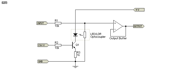
This combination has always been one of my favourites, and has been used in many products I've designed and manufactured over the years. These include live sound mixers, a studio mixer, innumerable stand-alone limiters, and it's also used in Project 137 (a complete preamp, crossover & power amp unit for powered PA boxes) as well as a couple of other projects.
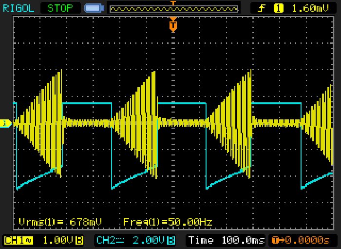
You may well look at the above and think "Step response? What step response?". As noted, LDRs are fairly slow, and their recovery time is much slower than their attack. This is one of the reasons that a very simple LED/LDR circuit can be used with no significant side-chain processing, because they tend to suit a lot of music surprisingly well using their own time constants.
Because the LDR is slow, the modulation frequency used was only 3Hz, and you can see that attack is reasonably fast but the signal slowly ramps up when the LED turns off. Even at 3Hz, there is nowhere near enough time for the signal to get back to its maximum (which was about 3V RMS). The full recovery time is typically around 1 second, but this also depends on how much LED current was used. At high LED current, it takes a lot longer for the LDR to recover and approach its normal dark resistance.
JFETs have been used in some of the most famous and 'revered' compressor/ limiters ever made. A junction FET (JFET) is passably linear over a fairly small range of drain voltages (AC), and it acts as a voltage controlled resistor. The maximum signal level is quite low - typically no more than 30-50mV, which means that noise can be a problem because the input signal must be attenuated before the FET, then amplified again after processing. This is not something unique to FETs though - discrete LTP circuits and OTAs also require that the input voltage is no more than a few tens of millivolts. Please note that Figure 7.1 does not include JFET static biasing. Normally, the source voltage is made high enough that the JFET is turned off, and the control voltage turns it on. N-Channel JFETs as shown are depletion-mode devices, and need the gate to be negative with respect to the source to be turned off. Most side-chains provide the negative voltage with no signal, and this is assumed for Figure 7.1.
A JFET used as a 'variable resistance' follows a square-law, and introduces a large second harmonic component - typically up to 25% THD with 50mV on the drain and at 6dB attenuation. To counteract this, it is essential that part of the signal on the drain is applied to the gate to cancel second harmonic distortion. The gate should have exactly half the signal that appears on the drain for optimum distortion cancellation. Over the years, this has been derived in a number of ways, with the most common shown below in circuit (A).
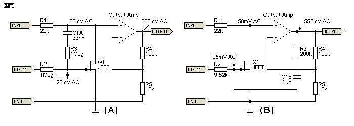
However, there is a problem with the standard arrangement (A) that's not immediately apparent. If the CV increases rapidly (from an input transient and a fast attack time), the two 1MΩ resistors act as a voltage divider because the capacitor (C1A) is not charged, so the gate gets (initially) half the applied control voltage until the cap charges. This causes the output voltage to overshoot, which causes the control amplifier to generate a higher control voltage, so gain is then reduced too far. It takes time for the system to stabilise, depending on the attack and release times that have been set. The effect sounds really bad (it can become unusable because it's unpredictable), and it is imperative that the control voltage rise-time is slow enough to allow it to reach a steady value without attenuation as the coupling capacitor charges.
Several methods have been used by various manufacturers to mitigate this effect, and Project 67 is a good example of a method that works very well. Somewhat surprisingly, there are quite a few commercial designs that use the exact circuit shown in (A) above, and despite claims that very fast attack time is possible, this is not necessarily the case. In general, it is not possible to use this method with an attack time faster than ~2ms or so (however, see below for other solutions).
To prevent heavy distortion of bass frequencies, the coupling capacitor needs to be as big as possible, but this simply makes the delay longer as the cap charges. The 33nF cap shown in circuit (A), along with the two 1M resistors, provides a low frequency response of around 2.4Hz, and this is required to get the 1/2 voltage at the gate at the lowest frequency of interest (in this case, ~24Hz). Note that the resistors are in series - the gate of the JFET is effectively an open-circuit, so the only loading is from the CV and audio sources. As the cap charges, a small amount of the control voltage will be impressed onto the audio (CV feedthrough). This can also be a major problem if a fast attack time is used! (See Figure 6.2.)
The arrangement shown in (B) is similar to that used in P67. The gate still gets exactly half the AC drain voltage, but the capacitor charging current is no longer a limit to the speed of the control signal because of the large resistance in series with the cap (C1B), and the relatively small resistance used to provide the control voltage to the gate. There is also zero CV feedthrough, because the capacitor charging current is returned to a low impedance - the opamp output. Despite appearances, the input impedance for a steady state (DC) control voltage is effectively infinite in both circuits.
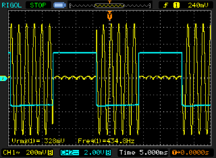
In the above, the signal frequency was set to 440Hz and the modulation frequency at ~30Hz. Response is close to instant, and in that respect it's almost as good as the THAT2180 VCA. Distortion is higher, and the maximum signal level is significantly lower (about 450mV - ok for testing but much too high to get acceptable distortion performance). At any higher input voltage, distortion was easily visible. You can also see that there is some evidence of control voltage feedthrough - the low-level signal is not centred around zero, and not because the oscilloscope trace wasn't centred. This is a pretty harsh test, but it does show that there is no inherent speed limitation with a JFET.
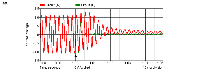
The red trace shows the control voltage feedthrough for circuit (A), and the green trace shows the (B) circuit response. Both circuits were subjected to a 1.5V CV step with a rise time of 5ms (from -2.6V to -1.1V) at exactly the 1 second mark, and it is quite clear that the (A) circuit shows considerable feedthrough and poor attenuation for the full 50ms period shown - feedthrough remains significant for at least 150ms. In contrast, the green trace (for the (B) circuit) shows an almost immediate reduction in level, with virtually zero feedthrough. The control voltage appearing at the output of the amplifier stage will be passed on to the rectifier and messes up the attack response rather badly.
If the (A) circuit arrangement is used, the only way to minimise CV feedthrough is to make the two 1M resistors higher in value (more than (say) 2.2M may cause problems due to PCB leakage as the product gets old), and reduce the value of C1A ... a minimum value of 10nF is suggested. While this can minimise feedthrough, it cannot address the delayed reaction of the control voltage because of the capacitor. The time constant of the RC network is a fixed quantity for a given LF limit, and reducing the cap value too far will increase distortion at low frequencies.
 | One alternative solution that has been used is to make C1A much larger than needed, so in normal use it can never charge and the control voltage is always attenuated. Some commercial products have used this method with apparent success, but it does not address the issue of feedthrough unless the 1/2 voltage resistors are at least 2.2MΩ. The amount of feedthrough is determined by the ratio of the resistance from the control voltage circuit to the drain, and the total effective impedance of the signal feed resistor and JFET (the latter two are effectively in parallel). As seen from the graphs in Figure 7.3, feedthrough can still be higher than expected, despite the apparently large attenuation. |
With both versions shown but particularly with Version 'B', it might be necessary to make one of the gate resistors adjustable so that a perfect distortion null can be set. The use of 1% resistors is usually acceptable, but be aware that the 1/2 voltage on the gate is critical for minimum distortion. Although I have seen it suggested that the 1/2 voltage need not be especially precise, my tests and simulations indicated that it is extremely critical, with even a tiny error causing a large distortion increase. For example, just changing the 9.52k resistor to 10k increases the distortion by 3 times!
It's rather unfortunate, but the number of suitable JFETs has shrunk alarmingly over the past few years. This makes JFET limiters less attractive because you may have great difficulty finding FETs that work well in this role. With each passing year, the number of devices you can get seems to shrink even further.
Although it's entirely counter-intuitive that a normal small signal bipolar junction transistor (BJT) could possibly work as a VCA, they have been used. This isn't something you'd find in professional equipment, but BJT based limiters used to be fairly common in portable cassette recorders, and it's entirely possible that newer digital versions use the same thing. Performance is decidedly low-end, but distortion can be acceptable as long as a) you have low expectations and b) the voltage across the transistor is limited to no more than 20mV RMS or so. This is already a significant limitation because the working voltage is so low.
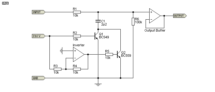
Control voltage feedthrough may be an issue with this circuit, because the collector voltage will always vary a little, along with the base voltage. However, in the arrangement shown the CV feedthrough is not overly obtrusive, showing around 3mV momentary DC offset when a 50mV input is reduced to 10mV RMS. With an input of 50mV RMS the distortion will remain below 2% at almost any output voltage. This is hardly a wonderful result though, and there are no easy ways to apply distortion cancellation. The parallel PNP transistor driven with the opposite polarity control voltage helps (a bit), but that negates the extreme simplicity ... and it still has poor performance. The simplest version has no inverter, and a single NPN transistor. Distortion is at its maximum with around 6dB of attenuation.
Although interesting, this is not a recommended approach due to excessive distortion. It was used in low-end equipment for one simple reason - it's very cheap to build. Bipolar transistors are a few cents each at most, and this was the driving force for the use of a BJT in budget gear. In a basic voice recorder with low fidelity at the best of times, no-one is likely to even notice the extra distortion. It's really a voltage controlled attenuator, but that's a moot point as many other schemes are no different in this respect.
Diodes have also been used as a gain control element, relying on the dynamic resistance of the diodes changing with current provided by the control voltage. Linearity is traditionally rather poor (which means distortion is high), and it's a technique that has generally been limited to low cost consumer items like portable cassette recorders and the like. However, if properly done and with the input voltage limited to ~50mV maximum, the distortion can actually be fairly low (below 0.1% as simulated, but considerably more when bench tested). The diode attenuator requires a control current, but that's easily derived from a voltage by using a resistor.
It is difficult to ensure that CV feedthrough is minimised, so there may be a fairly large DC shift as the control voltage/current is changed. This means that fast level changes (as needed for a peak limiter for example) will cause large transients on the signal output. This rather limits the usefulness of diodes as a gain control element, although the circuit shown has minimal CV feed-through provided the diodes are perfectly matched for forward voltage and provided they are very well thermally coupled. The diode current is generally extremely low - it only requires around 100uA to obtain 40dB attenuation, based on the example circuit shown below. The Siemens U273 limiter is only one of two serious devices I've been able to locate that use diodes for gain variation.
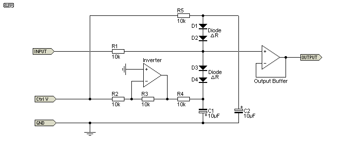
The inverter provides a second control voltage that is exactly equal but opposite to the incoming CV. With matched diodes there is no DC shift as the CV is applied, because the positive and negative voltages cancel. Getting matched small signal diodes isn't easy these days, so this is something that you'd have to do yourself.
This type of attenuator works by utilising the dynamic resistance (ΔR) of the diodes. Dynamic resistance refers to the fact that the resistivity of the silicon junction is heavily dependent on the forward current through the diode(s). At very low (or no) DC current, the diodes have a very high resistance, and none of the signal is shunted to earth. Even a few microamps is enough to reduce the resistance, some of the signal current is shunted to earth, and the signal level is reduced. Unfortunately, the dynamic resistance is a non-linear function of forward current, and this is the reason for the relatively high distortion. As noted above, just 100uA is enough to cause the dynamic resistance to fall from many megohms to around 100Ω. The signal is shunted to earth via the two 10µF capacitors.
Note that the diode attenuator shown is only a basic concept - it will work for simulation or bench testing (as an attenuator), but is rather slow because of the resistor/capacitor time constant. To get fast response requires additional circuitry. Indeed, the circuit complexity is such that it is far easier to use a JFET, which gives equivalent or better performance with a much simpler circuit. It's not surprising that diode VCAs are uncommon.
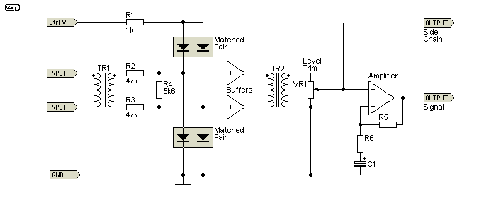
It's been brought to my attention that Neve (of mixer fame) also made a compressor/ limiter that used diodes [ 11 ]. The key to it's performance is twofold - firstly, the voltage across the diodes is very low (-31dBu), and secondly, the signal is transformer balanced. The diode pairs must be matched, and the transformers ensure that no CV feedthrough can occur. The concept circuit is shown above, and it will be apparent that it would be very expensive to build, because the transformers must be very high quality. Again, only a low current is needed from the CV line, with about 40µA needed for 6dB attenuation.
It's unlikely that anyone would try this today, although it will almost certainly work with electronically balanced inputs and outputs instead of transformers. I have experimented with simulations, and both electronically balanced and the transformer version are surprisingly good, with far lower distortion than I expected. With 6dB of attenuation (which is generally the worst case), the simulator reported a distortion of less than 0.01%, which is a very credible performance. Ultimate gain reduction is about 45dB, which is probably as much as anyone needs in this role.
It's apparent that using a balanced signal path is preferable to using a balanced control voltage, and isolating the signal with transformers at each end of the chain is worth the effort. The voltage across the diodes must be kept to an absolute minimum, consistent with acceptable noise performance. The Neve circuit uses attenuation to get a nominal signal voltage of under 30mV, and when the Figure 9.1 circuit is supplied with a similar voltage, its performance is also improved (but it remains worse than the Figure 9.2 circuit). By utilising a balanced circuit for the signal, even-order harmonic distortion is cancelled, and the remaining odd-order harmonics are at a much lower level.
PWM is a technique that's been used by a small number of manufacturers over the years [ 5 ], but for reasons that I initially found mystifying, it has never been popular. The idea is that the incoming audio is fed through a fast switch (such as a CMOS 4066 quad bilateral switch) that is controlled using a variable duty-cycle control voltage. The output is then integrated or just passed through a low-pass filter to recover the audio. Since the switching speed can be very high (up to 500kHz isn't a problem) it's quite easy to get rid of any RF noise on the audio. In a practical circuit, a lower switching frequency and sharper filters are probably the only way to build a functional PWM VCA.
This method has the advantage that multiple units can be used, and they will all track perfectly. Distortion is ultimately determined by the CMOS switch, but it's fairly easy to keep THD below 0.1% at all levels from a few millivolts up to 3V RMS or so. A PWM attenuator can be used as a multi-channel volume control with perfect tracking, or as the level controller in compressors and/or limiters.
The input signal is switched so that it becomes a series of pulses at the switching speed. The CMOS switch is arranged as a SPDT (single pole, double throw) type, and the input to the filter is alternately connected to the signal input (SW1) or earth (SW2). The second switch is important - if it isn't used, the output will not track the switching pulse width properly. At 50% duty cycle, the filtered (or integrated) output voltage is exactly half the input voltage. As with any digitising scheme, the switching speed must be at least twice the highest frequency to be processed. The output filter removes the switching frequency, leaving the integral of the 'chopped' input signal. To increase the level, SW1 is simply on (SW2 off) for longer and vice versa for lower levels. If the lowest duty-cycle available is 1% (on for 1% of the time, off for 99%), the output level is 40dB below the input.

While it's easy to simulate the circuit, realisation in practice is less easy. If the opamp used for the low-pass filter doesn't have adequate gain at the switching frequency the filtering will be poor and distortion higher than expected, so it requires extremely fast opamps or passive inductor/ capacitor filters. In addition, the PWM signal requires a fast comparator to get the required variable duty-cycle switching waveform. Even small amounts of amplitude drift in the comparator or oscillator circuits will cause comparatively large level changes. This isn't a problem with a compressor/ limiter, because it will self-correct, but if used as a volume control (for example) any drift will cause the level to change.
Needless to say, a fully digital pulse generator will solve this problem neatly, but requires either a fast microcontroller (at least 10MHz for 0.5% duty cycle resolution at 50kHz output) or a fairly large number of discrete logic ICs. It is unlikely that any digital pulse generator will be fast enough for a peak limiter, especially if an attack time of less than a few milliseconds is desired.
PWM has only been used by a small number of manufacturers, and I've been unable to find out why it's not more popular. While there are some very obvious reasons (circuit complexity compared to a plug-and-play VCA chip for example), it is a technique that has some appeal because of the almost complete freedom from distortion - other than that created by the CMOS switch. From looking over datasheets, some of the better dedicated VCA ICs are likely to have lower distortion than a CMOS switch, and are both cheaper and a great deal less complex overall. I think I just answered my own question 
DSP (digital signal processing) can produce excellent results, but until recently only for static level control. While DSP based compressor/ limiter circuits are common, there is often inherent latency within the ADC (analogue-digital converter) as well as during processing. This causes the signal to be delayed - usually only slightly, but it could be for long enough to cause problems with some systems. Look for a system delay of no more than 1.5ms and the resulting delay should be inaudible. Many commercial products exist, but this is not an approach that is generally suited to DIY or basic experimentation. None of this matters in a DAW (digital audio workstation), because the system will ensure that all outputs are delayed by the same amount.
DAW systems have many 'plug-in' compressor/ limiter software available, with digital emulations of just about every 'classic' compressor available (some at considerable expense). These mostly have a digital representation of the knobs and switches of the device being emulated. As with any digital representation of an analogue system, the devil is in the details. Some may be very good (sounding close to identical to the original hardware), while others not so much. I don't have (or need) a DAW, so I can't comment on the performance of these software emulations.
One area where digital processing has been used is to delay the incoming signal slightly so the gain control element (regardless of type) can set the correct level at exactly the moment the transient or unwanted signal arrives. This is not generally usable as a live sound technique because of the delay, but was a feature of some 'de-click' circuits used with vinyl records. These units usually only had a fairly crude gain control element, because it was designed to reduce the level of clicks and pops due to dust or disc surface damage. Most intercepted the signal for less than 1ms, just long enough to remove the offending click, but not long enough to be audible. Certainly, even if the effect was audible, it was far less intrusive than a loud click. The feature is available in many audio processing programs (such as Audacity and several stand-alone utilities).
As noted above, there are numerous plug-ins and other software based compressor/ limiters that work directly with PCM audio files on a computer. Although mostly not usable in so-called 'real time', they have the advantage of predictive behaviour - the software can analyse the transients and reduce the gain at the very instant that the transient occurs. This is equivalent to having a hardware based system with zero attack time, which cannot be achieved unless the signal is delayed.
Digital potentiometers are a potential way to implement a VCA, by using a PIC microcontroller or similar to send the appropriate code to the pot based on a voltage level. Although this technique has not been investigated, it is probable that the delay caused by the PIC (as it decodes the input and sends the digital control signals to the pot) would be such that it would be unusable for use in a compressor or limiter. Because of this and discrete level steps (rather than smooth analogue control), the performance will almost certainly be somewhat south of woeful. As a general-purpose level (volume) control where speed is not an issue, digital pots are common.
While they offer very low distortion and ease of use (thanks to a microcontroller), digital pots don't really qualify as VCAs. They are unable to do things that we expect from a VCA, such as operate in the analogue domain and provide stepless level control.
Another option that was suggested by a reader is to use a multiplying DAC (digital to analogue converter), commonly known as an MDAC. The audio signal is applied to the reference input, and the control signal is from a microcontroller or other processor. Some MDACs allow a bipolar reference voltage so input level shifting may not be necessary. This isn't an approach that I'm familiar with, so if you want to know more you'll have to download data sheets and other material.
I've recently been made aware of another technique that was first used in the 1950s, and which (apparently) still has a dedicated following. The Altec 436 compressor was originally intended for use with telephone monitoring and/ or transcription, and one of the documents I found has a number of case studies describing how it improved recordings taken from phone lines. This should come as no real surprise, as so many of the things we take for granted were originally developed for telephony/ communications (the valve and transistor are especially notable).
Replica units using modified circuitry are available from a few suppliers, but at considerable cost. There's a requirement for input and output transformers, and these are expensive, as they are custom made. No transformer maker offers anything that can be used easily, so a custom design is the only option. This section is a little different from the others, in that the side-chain is shown on the circuit, but only because it's not sensible to leave it out as it's an integral part of the system. The grid voltage to V1 can be up to -30V with 20dB of compression, demonstrating that the 6BC8 really is a 'remote cutoff' type.
The use of 'variable-mu' valves was (as near as I can ascertain) first used by Altec, then improved by the engineers at EMI's Abbey Road studios (recording The Beatles in particular Note 1). These valves are intended for use as AGC (automatic gain control) in RF (radio frequency) receivers, typically as intermediate-frequency amplifiers, but they also work with audio frequencies. The valves used (typically the 6BC8) are described as a 'medium mu, with semi-remote cutoff characteristic'. This means that the transconductance (mu, or µ) can be changed by varying the DC grid voltage. The grid isn't wound in a tight spiral as is the case with most valves, but has variable spacing along its length. The closely-spaced section(s) will turn off early, but the wider spaced grid wires need far more negative bias to turn off. The gain of the stage depends on the transconductance, so it varies when the DC grid voltage is changed. Bias and signal are applied to the grid, and two valves are used in push-pull (with antiphase grid signals) to cancel the (considerable) distortion produced.
1 The above claim is disputed on some websites, claiming that the Fairchild 670 compressor was used at Abbey Road. I cannot determine who is right (or wrong) on this point, but it's fair to assume that both may have been used at various times. The few circuits I found looking for 'Abbey Road Compressor' most certainly show modified Altec schematics, not Fairchild 670. The latter is very large, very heavy and (apparently) extraordinarily expensive if one can be found, and it uses far more valves than the Altec 436.
The following is a simplified circuit of the Altec 436 variable-mu compressor/ limiter. The component designators are mine, as few of the circuits I saw used them. The operation of the circuit is fairly straightforward, with V1 being the dual variable-mu triode. The control voltage is applied to the grids via the transformer centre-tap (and the input dual-gang pot). It's derived from the signal via V3, a dual diode. As the signal level increases, more negative bias voltage is applied to V1 grids, reducing the gain. The meter indicates the cathode current, which is at maximum when there's no compression (minimum grid bias voltage). The power supply isn't shown, but it (apparently) originally used a selenium rectifier and basic capacitor filtering.
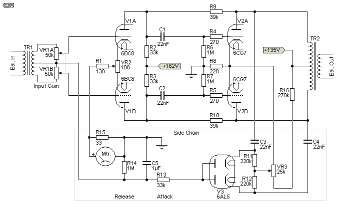
I haven't shown the output attenuator, nor variable settings for 'Attack' and 'Release'. These are set by R13 and R14 respectively, along with C5, and are either switched or may use rotary pots. EMI apparently preferred switched settings, because they were more easily duplicated at a later date (provided someone noted the settings of course). V3 obtains a signal from both halves of the circuit, so it has full-wave rectification, which IMO is essential for good performance. VR2 and VR3 are used to obtain optimum symmetry in order to minimise distortion.
The circuit shown was modified from the original Altec design, and some of the mods look like they have been done to reduce distortion (which Altec doesn't appear to specify in any documentation I found). In particular, R9 and R10 provide negative feedback to the input (variable mu) valve, which reduces the gain and distortion, and provides a 'softer' compression rate. These resistors are not included in the Altec circuits and may or may not be included in any circuits you come across.
There are several manufacturers offering variable-mu designs, but they are mostly very expensive. Much of this can be attributed to the transformers, as they aren't 'off-the-shelf' types, and would have to be custom made. An issue will always be obtaining replacement valves, particularly V1. V2 drives the output transformer in push-pull. The use of a push-pull configuration cancels even harmonic distortion, so the balance of the two halves of the circuit is critical. It also ensures that control voltage feedthrough is cancelled - this is important, as the plate voltage of V1 varies dramatically as the grid voltage is changed.
Interestingly, the circuit simulates reasonably well using 12AX7 valves for V1 and a 12AU7 for the output (V2). I haven't built one (and don't intend to), but at least the simulator claims acceptable distortion (less than 2%), but mediocre linearity. This doesn't matter for a compressor, but it's not useful for a VCA. With the side-chain connected, compression is 'soft' so it can compress well enough, but probably not well enough to be a true limiter. The attack time is limited due in part to the relatively low current capacity of the valves.
There are (apparently) people who think that these variable-mu compressors are the 'bee's knees', while others are ambivalent or even disparaging. I've not heard (or tested) one in my workshop, so I cannot comment one way or another. According to documentation I located thanks to some tips from a friend, they are typically capable of around 30dB of compression at the most. The compression is 'soft', so the technique is not really suitable for limiting (although this can be changed by adding gain to the signal chain).
As noted in the introduction, every approach has limitations. Some are financial (proper VCA chips or custom transformers are not inexpensive) and others have significant technical issues. For a cheap and cheerful peak limiter that operates at relatively high levels and has low distortion, the LED/ LDR combination is hard to beat, but the LDR is fairly slow and very fast attack isn't possible.
FETs can be made to work well, but the signal level has to be kept low or distortion becomes a major problem. The version shown in Figure 7.1(B) is the only variant that can be recommended, otherwise control voltage feedthrough becomes irksome. While the majority of the feedthrough can be eliminated by means of a high pass filter, this will create other issues - not the least of which is limited low frequency response.
OTAs can be used where the application isn't critical. For speech compression/ limiting used with communications transmitters or announcement public address it would not be sensible to use a highly specified laser trimmed VCA chip, because an OTA is all that's needed. However, using an OTA based compressor/ limiter for studio recording or live sound is ill advised because they aren't good enough. In addition, OTAs are no longer as readily available as they once were (virtually all the common ones are now obsolete).
It's hard to recommend using diodes or PWM because the circuit complexity is such that it's actually cheaper to use a VCA. The performance of diodes is usually worse than any FET, so there's simply no point (the Neve approach is better than a 'simple' design, but expensive due to the transformers). Discrete long-tailed-pairs are cost-effective, but are not high performance solutions, regardless of the technology used (bipolar transistor, JFET or vacuum tube). Single bipolar transistor VCAs are cheap, but distortion is excessive and they are completely unsuited to anything other than very low-end consumer products.
There are three approaches that (IMO) deserve consideration for DIY - a true VCA, LED/ LDR and JFET. All have been used in highly regarded products over the years, and the final choice depends on the application and expectations. There is never a single solution to a problem, and personal preferences (or client demands) may indicate the use of a technology that is otherwise considered sub-optimal. The variable-mu valve approach is interesting (I'd love to be able to test one), but the cost is hard to justify.
Peak limiters (in particular) will distort the first 1-3 cycles of a sharp transient, especially if it's a moderate to high frequency (>~500 Hz) and arrives out of relative silence. Even if the gain reduction is instantaneous, the original waveshape is modified as gain reduction is applied. If the shape of a signal's waveform is changed, then it is, by definition, distorted. Fortunately, our ears tend not to hear very short periods of distortion, and the easiest way to prevent high-level transients from getting past the limiter is to add a clipping circuit.
This is routine in critical applications such as radio transmission, because even momentary over-modulation causes problems, where spurious RF frequencies are generated, (commonly known as 'splatter'). Transient clipping is common with live sound (so is continuous gross clipping in some cases), and even some CDs are pressed pre-clipped to save you the trouble. Compression and limiting are tools to be used wisely, but they don't have to be obtrusive and if done properly hardly anyone will notice. I long for that to happen.
These references are in no particular order, and most are not indexed through the text because some are referenced several times, and others only as a passing comment. They are not linked to any websites - some because there is no legitimate website (just schematics and other material that's been posted in forum sites or elsewhere), others because there is no website at all. Datasheets can be found on many different sites, but not always including the manufacturer's site (for obsolete parts). Many websites also change the location of material for no apparent reason, so 'live' links often disappear.
 Main Index
 Articles Index