
|
|
| Elliott Sound Products | Bucking Transformers |
 Main Index
Articles Index
Main Index
Articles Index
Before I describe or explain any part of the information on this topic, you must be aware that ...

Everything in this article involves working with mains voltages. Do not attempt construction or experimentation unless you are skilled and/or qualified to work with mains voltages. In some jurisdictions, mains wiring must be performed by suitably qualified persons, and it may be an offence to perform such wiring unless so qualified. Severe penalties (including an accidental death penalty) may apply. No ... I'm not kidding.
Note that both the primary and secondary windings are at mains potential, and there is zero isolation. This is not a problem for mains powered equipment, but if you are careless it could take you by a very great and dangerous surprise ! The mains earth must be connected between input and output.
There is regularly a need to reduce the mains voltage. In some cases, it's because where you live it's just too high and causes problems with electronic equipment. Sometimes, you might have a great transformer for a project, but the voltage is just a bit higher than recommended. A very common requirement is to be able to use 220V equipment at 240V - while this is within the 'normal' range, it can be bad news for some gear. Valve amplifiers in particular can be fairly fussy, and there's definitely a need to reduce the voltage if the heater voltage is much above the typical nominal value of 6.3V.
Many of the articles on the Net also suggest that a bucking transformer can be used in boost mode. Perfectly true, but there are times when this is a very, very, bad idea. Most of the material I've looked at leaves out a great deal of the info you need, so I figured it was time I described the process properly, and ensured that you have all the information needed to build a safe bucking transformer system. A great many of the search results for 'bucking transformers' point to questions being asked on forum sites, so it's obvious that they are not well understood, and often not explained very well.
For the purpose of the exercise here, we'll assume that the mains voltage is 240V and the maximum load is 220V at 10A (2,200VA). This is a large transformer, which will be heavy and expensive. We'll also look at a mains voltage of 120V with a requirement for 110V at 20A - also 2,200VA. Note that transformers are always rated in VA (Volt-Amps) rather than Watts. The two figures are only the same when the load is purely resistive. Most loads are either reactive (contain capacitance or more commonly inductance) or are non-linear. Nearly all electronic circuitry presents a non-linear load.
In each case below, I will only show a basic arrangement, because that will be the most common. There are countless variations that may be provided on some commercial or custom-built products, but including all possibilities is both pointless and impossible.
 | All transformer windings shown have a dot at one end. This is the traditional way to indicate the start of a winding, so that windings can be connected in series or parallel correctly. If winding polarities are reversed, the transformer will either give a completely different voltage from that expected, or you can even make the transformer look like a short circuit across the mains. |
All voltages referred to herein are assumed to be (more or less) exact, but of course the mains voltage is 'nominal' (meaning in name only), and is subject to significant variations from day to day and even at certain times of day. Most equipment is designed to be able to cope with normal variations, but there are small differences that have crept into the mains voltage specifications over time that can place older equipment at risk. Imported equipment intended for a lower voltage (220 vs. 230 vs. 240 for example) can fail because either the voltage really is outside the allowable range or is simply incorrectly specified. In some parts of Australia (especially remote outback areas), it's not uncommon for the '230V' mains to measure 260V!
In the US, a lot of older equipment is designed for 110V (very old), 115V or 117V, but the 'correct' nominal voltage is 120V. If you use equipment that really was designed for 110V, but the mains at your house measures 120V and sometimes goes a little high (125V perhaps), the vintage gear will likely have a short life if used consistently at the higher voltage.
In some cases, you might simply want to extend the life of incandescent lamps so they last longer and you can keep using them after they are banned (this has already happened in Australia). Whatever your reasons for reducing the mains voltage by (say) 10-15%, the following will be useful and will allow you to do so cheaply and safely.
For this application, the first thing that most people think of is a step-down transformer. Since it will be rated at 2,200VA (2.2kVA) this is a big transformer, and it will be expensive. At around this size, you can expect a toroidal transformer to weigh in at about 12-14kg, not including any housing, connectors or anything else. A conventional E-I laminated core tranny will be larger and heavier - expect as much as 22kg for a 2kVA unit. Figure 1 shows the configuration of the transformer. As shown, there are no taps or adjustments - the ratio is fixed at 1.09:1 which will convert 240V to 220V or 120V to 110V.
You cannot use the same transformer for both applications! Transformers must be designed for the actual voltage and current at which they will be used. In many cases, and especially for trannies that are intended for a particular use in the country of origin, they will also be designed for the frequency used (50 or 60Hz). A 60Hz transformer is smaller than one designed for 50Hz, but may fail if operated at the lower frequency.
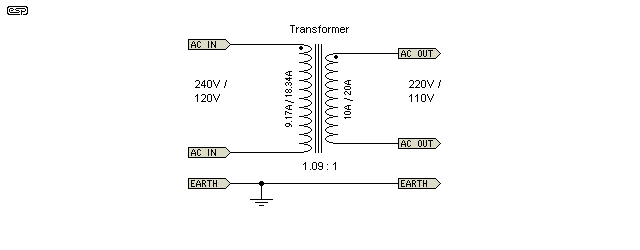
Figure 1 - Conventional Step-Down Transformer
There are many variations. Tapped secondary windings may be provided to give more range and a closer match. While tapped transformers are useful, they are (or should be) reserved for more critical applications. The number of taps provided can vary widely, and there are many possible variations. Adding taps increases the size and cost slightly, but also gives the non-technical user many opportunities to use the wrong tapping and cause damage to equipment.
While the standard step-down transformer is a good solution for our specific goal, it is the least efficient and most costly. It will also introduce a couple of problems. One is that the extra resistance of the windings will reduce the regulation of the mains supply, so the voltage will fall further than normal at full load. Regulation can be expected to be no better than about 4%, meaning that the output voltage will fall by at least 4% when the load is increased from zero to full power.
The second issue is more serious - it renders any safety switch useless for the equipment on the secondary side of the transformer. Safety switches have many names, depending on where you live. They may be called core balance relays, earth leakage circuit breakers, ground fault interrupters, etc.
Needless to say, this limitation is by far the most important, although reduced regulation may be a major issue in some cases. There is a very small number of applications where isolation of the mains is required along with a small step down (or up) of voltage. Operation of household equipment - TV sets, hi-fi (valve or transistor), kitchen appliances, etc. - never requires isolation, and because it defeats the safety switch has to be considered a bad idea.
If used for 240-120V step down applications, I recommend very strongly against using an autotransformer b cause they can be very dangerous with some equipment (old US made guitar amplifiers for example). In this article, we are looking at only a small reduction of voltage, there are no issues with electrical safety, and an autotransformer is perfectly alright here (see Importing Equipment From Overseas ... for more on the safety issues). An autotransformer is shown below - there are no longer two separate windings - everything is handled by a single winding with a tapping that gives the same 1.09:1 ratio as before.

Figure 2 - Step-Down Auto-Transformer
In this application, the autotransformer has a number of advantages. Because there is only one winding, thicker wire can be used and a smaller core is suitable, and regulation will be better and the transformer can be made smaller and lighter. You can even have both - better regulation and smaller, lighter and cheaper, and not break the laws of physics. Outstanding  .
.
In addition, your electrical safety switch still provides protection, although with a small reduction of sensitivity. Overall, this is a great solution. It would be the ideal solution if auto transformers were always wound properly, since the size can be reduced dramatically. Sadly, this may not be the case unless you have a tame transformer winder who knows what he's doing. You could easily end up with a transformer weighing about half that of an isolation transformer, where it only needs to weigh a couple of kilograms at most. In addition, whatever you need will be a custom job, since I know of no transformer makers that produce a stock range of autotransformers (other than 240/220V - 120V and vice versa).
The ultimate autotransformer is a Variac which allows continuous variation of the mains voltage from zero to (typically) 110% of the applied voltage. For critical applications, Variacs have been fitted with servo systems that automatically adjust the setting to maintain a very stable mains voltage, regardless of variations caused by normal fluctuations. Such a system will not be described here, as it is completely outside the scope of this article. Variacs are also rather expensive, especially in larger sizes.
The bucking transformer has been around for a long time - probably almost as long as transformers themselves. The primary reason for using a bucking transformer instead of a traditional step-down transformer is size and cost, and because of this people often assume that it must be a bit dodgy and not as good as a 'real' transformer.
This is not the case at all - a properly designed bucking transformer will perform just as well (or better) than a step-down. Like the autotransformer, there is no isolation, so the mains voltages are just as dangerous as they always are, however, the safety switch is still functional so you are protected.
A bucking transformer is really a modified version of an autotransformer. The difference is that only a small part of the winding has to carry the full load current. This is a commonly overlooked aspect of an autotransformer - looking back at Figure 2, only the top section of the winding carries the full load current, so the remainder of the winding can use a smaller wire gauge than may otherwise be used.
The bucking transformer works by placing the secondary of a (relatively small) transformer in series with the mains, but wired out-of-phase so the voltage is 'bucked' or reduced by subtraction. Only the secondary winding needs to carry the full mains current. This means that for 240V to 220V we need to 'buck' 20V at 10A - a maximum of 200VA. Likewise, for 120V to 110V, we only need to buck 10V at 20A ... also 200VA.
To understand how the bucking action works, it's just a matter of remembering some basic school maths. If a transformer winding is wired out-of-phase, it can be given a negative sign. In our examples, we will have 240V + ( -20V ), which equals 220V (try that on a calculator if you don't believe me). Likewise, for 120V we end up with 120 + ( -10 ) = 110V. It really is that simple .
At the end of this exercise, a 200VA transformer wired as a bucking tranny does the same job as a 2,200VA conventional transformer. The 200VA transformer can be expected to weigh less than 2kg (again excluding case, connectors, etc.). This is not only a significant weight and size reduction, but it will also cost far less than a conventional transformer. This seems too good to be true, but it really does work as described. This is probably as close as you can get to the much hoped for (but disallowed by the laws of physics and the taxman) 'something for nothing'.

Figure 3 - Traditional Bucking Transformer
The schematic above shows how it's done. The voltage in the secondary is wired out-of-phase, so removes (by subtraction) the secondary voltage from the mains voltage supplied to your appliance. The maximum current that flows in the secondary is the full load current, so is 10A at 220V or 20A at 110V. Regulation can be improved by using a slightly larger than necessary transformer if it's critical, but it will still be far cheaper and lighter than a conventional transformer. At 240V input, the primary current is a mere 833mA at the maximum load of 2.2kVA. Predictably, this increases to 1.66A for the 120V version. The regulation from your mains supply will be worse than that of the bucking transformer in most cases.
Because your safety switch is not disabled, there is no increased risk of electric shock. If you ever need to reduce the mains voltage by a set amount to improve the longevity of an appliance, this is a cheap and effective way to do it. In many areas, the mains voltage can be significantly higher than the nominal, and this is a simple and cost-effective way to reduce the voltage to something that doesn't cause your expensive equipment to blow up at regular intervals. Take special note of the winding polarities, and make sure that you test your wiring (with a mains voltage filament lamp in series with the mains in case of a serious mistake).
What is commonly overlooked when auto transformers are specified, is that the requirements are actually almost the same as for a bucking transformer. As a result, there is no reason not to connect your bucking tranny as an autotransformer. This means the normal thin primary wire for the majority of the winding, and thick secondary wire only for the high current part of the winding. Current in the lower section of the winding is reduced to 775mA for the 240V version. From this, we can do a bit of lateral thinking and reconfigure the bucking transformer so that it works properly. This increases the output voltage by a small amount - it will be of no consequence in most cases. This is just as cheap and effective as the bucking transformer shown above, but is slightly more efficient.
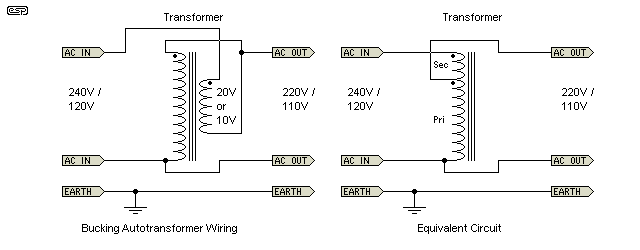
Figure 4 - Proper Way To Wire A Bucking Transformer
You won't see this arrangement described very often (if at all), but it is a far better solution. In Figure 4, I have simply rewired the circuit as an autotransformer, and the equivalent circuit shows that this is indeed the case. The transformer is exactly the same as used in previous examples. The incoming mains connects across the entire winding ... the primary in series with the secondary, wired in phase. The output voltage is taken from the tap - this is identical in every way to a normal autotransformer connection. The output voltage is fractionally higher than with the bucking configuration - the 240V version gives 221.5V RMS output (110.75V RMS for the 120V version). Again, double check all winding polarities before connecting to any equipment.
You can also push this version a little harder than a traditional bucking transformer. The normal output current (based on our initial criteria) is 10A at 220V, but with the arrangement shown in Figure 4 you can have an output current of about 10.8A (a total of 2,400VA) without exceeding the transformer's secondary current rating. That's because the currents are subtracted within the winding itself, because of the transformer action. The main primary runs at a current of about 835mA at the maximum output of 2.4kVA.
A simple reconfiguration of an old technique therefore provides better efficiency and lower losses than the traditional bucking transformer. It is important to understand that we are not getting something for nothing, we are simply minimising losses. In the following drawing, voltage waveforms are shown in red, current in green.
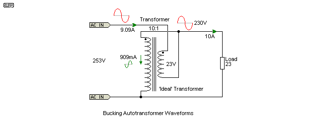
Figure 5 - Bucking Transformer Waveforms
Largely due to a reader who was very puzzled by the claimed primary current (in particular), I thought it would be worthwhile to show the voltage and current waveforms, using an 'ideal' transformer so that iron and copper losses don't confuse the issue. The details are shown above, and I aimed for the simplest case possible. This means a 10:1 transformer, a desired output voltage of 230V, and an actual input voltage of 253V (23V too high). The input voltage and current are in phase because the load is a resistor. The input power (V × I) is 2,300W (2.3kW).
The output voltage is 230V at 10A, again, a power of 2,300W. Note that the transformer's primary current is 909mA, and is 180° out-of-phase. That causes it to be subtracted from the input current, reducing what you might expect to be 10A back to the 9.09A measured. There are small inaccuracies because I rounded the figures to three decimal places, but rest assured that it all adds up perfectly.
Rearranging the circuit to the 'traditional' method shown in Figure 3, The output voltage is 227.7V (a bit lower than the design value) and the transformer's primary current is 990mA (a little higher than the case shown above). The power in and power out are still the same, but reduced to 2,254 watts because the output voltage is lower than expected. Because the transformer primary current is higher, there will be greater losses with a 'real' (as opposed to 'ideal') transformer due to winding resistance.
Although I used a 200VA transformer in the above example, if the transformer in the equipment you're using is (say) 300VA, then you only need a 30VA bucking transformer for a voltage reduction of 20V. The rating for the bucking (or boosting) transformer is determined by the voltage and current, so if you need to buck or boost by more than 20V (or the current is higher), the VA rating is increased, and for a lower boost/ buck voltage or lower current, it's reduced.
There may also be occasions where the voltage you get is consistently too low. The same technique can be used to give your supply a lift so that it's closer to where it should be. Be very, very careful with this setup though. It should only be used where the mains voltage actually needs to be boosted because it is always too low. You cannot use this trick to get a bit more voltage from a transformer or to get more power from an amp, because you will be operating everything at a voltage that causes additional stress. This could easily prove fatal for your equipment! Transformers can easily be pushed into saturation even with a fairly modest voltage increase.
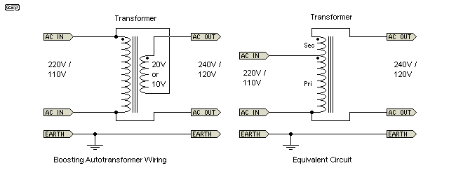
Figure 6 - Boosting Transformer
The transformer requirements are exactly the same as for a bucking transformer, except that the secondary voltage is now added to the incoming mains voltage, rather than being subtracted. A boost transformer can only be wired to create an autotransformer - there aren't any 'alternative' ways in which it can be connected. As before, your electrical safety switch still works normally.
Note that as shown in the equivalent circuit, the boost configuration is already wired as a 'true' autotransformer, and it can't be improved by any trickery.
Note that great care must be taken with construction and mounting of any transformer used as buck, boost or autotransformer. All parts of all windings are effectively at the full mains voltage, and insulation must be adequate to ensure that the end result is safe under all likely conditions (including faults). If the transformer has additional secondary windings, do not be tempted to use them for anything! The secondary is at mains voltage and the insulation between secondary windings is rarely (if ever) designed to withstand mains voltage, so any remaining secondaries are potentially lethal. Therefore, don't even think about using another secondary to power other equipment (for example). Your bucking (or boost) transformer must be dedicated to one purpose only!
The final assembly should be protected against excess current by a fuse (minimal protection) or a circuit breaker. Depending on the intended purpose, it may also be wise to include a thermal cutout (either self resetting or a one-time thermal fuse). The case, wiring and input/output mains connectors must also comply with all requirements as determined by the electrical codes where you live, and must always include a mains earth (ground). Ensure adequate ventilation for the transformer, consistent with the need to keep small fingers well away from dangerous voltages or sharp edges.
For a bucking transformer, the circuit shown in Figure 4 is obviously the most sensible. This is a true autotransformer, and the secondary winding no longer bucks (or opposes) the incoming mains. Efficiency is improved, and a given transformer wired this way can provide a little more output current than if it's wired as a bucking transformer. The small extra voltage should not be an issue, and in many cases will not even be apparent because transformers are wound to ensure that you get rated voltage at the maximum permitted current.
Naturally, if you want to use the traditional bucking configuration you may do so, but it will have worse regulation than the Figure 4 alternative. With typical winding resistances and 240V applied, a bucking transformer will provide 216V into a 22 ohm load (1.8% regulation), and the autotransformer configuration will give 218V (1.6% regulation). There isn't a big difference, but it's measurable. These regulation figures may be slightly worse for the 120V version because of the much higher current, however, the autotransformer configuration wins again.
Autotransformers (or bucking transformers) are best and most effective where the voltage change is relatively small - typically no more than a 20% change. The maximum ratio is 2:1 or 1:2 (double or half voltage) before any autotransformer becomes uneconomical and/or pointless. Even at this ratio (typically used for 110V equipment used in 220V countries or vice versa), there are risks and dangers that are not immediately obvious - especially when 110-120V US equipment is used in Australia, the UK or Europe etc. (220-240V). In this case, the only safe option is a proper isolated step down transformer. The article Importing Equipment From Overseas ... explains all the reasons.
Finally, consider the use of a larger transformer than theoretically necessary if the load is constantly close to the maximum. Such operation means that the transformer will run at a higher temperature than we might like, and it will be heavily stressed in use. Using a larger transformer gives better regulation and cooler running. Remember that the operating life of many electrical and electronic components is halved for every 10°C rise in temperature. This includes the insulation used in transformers, so cool running means a long trouble-free operating life and lower operational losses. The transformer described above (Figure 4) has a total loss of perhaps 20W at full power. This is power that you have to pay for, and over a period of time a larger transformer with lower losses may work out cheaper.
Although I looked at a few websites discussing bucking transformers, none had the level or depth of information that I feel is needed to understand the concept properly. That is one of the main reasons that this page now exists. On the strength of this it should be apparent that there are no references as such.
Even though there were no useful references for bucking transformers, EC&M (Electrical Construction & Maintenance) on-line magazine does describe the proper way to design an autotransformer (which verifies my approach taken in Figure 4), and includes formulae to allow you to calculate the required size for a given VA rating. The article also refers to drawings, but there are none that I could find.
The 'Dry-Type Transformer Study Course' by Square D Company was listed as recommended reading, but the link (and the document) no longer seem to exist. The article had some great info for those who really want to study transformers in more detail. The material describes mainly large trannies, all decidedly US-centric (60Hz, US distribution system, etc.) and concentrates on power distribution types. This does not change the principles though, which are just as valid at 100VA as 100kVA, 50 or 60Hz.
Main Index
Articles Index