
|
|
| Elliott Sound Products | Project 70 |
 Please Note: PCBs are available for this project. Click the image for details. PCB is P36 - there is no separate board for the headphone version.
As of January 2017, there are some updates to this article. The most significant is the reduction of the supply voltage (down from 35V nominal), and more info on expected power without the use of a 120 ohm series resistor, as these have fallen from favour due to the proliferation of small players that have a very limited supply voltage, and can't deliver useful levels when the resistor is used.
In early versions of the DoZ, the quiescent current could be quite unstable with variations in the supply voltage. Normal changes in the AC mains would often cause Iq to shift above and below the preset value. A simple modification is now included on the PCB that virtually eliminates the problem. It is reduced to the point where it is now immaterial.
You really need to see the original article - Project 36 - to see all the design details for this project. The project presented here is simply a modification of the original design, with much lower power dissipation and adapted specifically as a headphone amplifier. The circuit is identical to the original Death of Zen amp, except for the output transistors.
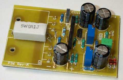
Photo of Assembled Early Rev-A Board
Class-A is ideal for this application, since headphones are such an intimate way of listening. An amplifier for 'phones should be as clean and free from crossover distortion as possible, and must also be quiet. A background of hiss and hum does nothing to enhance the listening experience.
Headphone amps are somewhat misunderstood, but in reality there are few points that need to be made. Some 'phones are designed to be operated with a source resistance of 120 ohms, and damping factor (as applied to conventional loudspeakers) is largely irrelevant. The actual source impedance should have very little (if any) effect on the frequency response or dynamic behaviour, since there is no cavernous enclosure and no heavy cones to try to control.
The IEC 61938 international standard recommends that headphones should expect a 120 ohm source (5V RMS maximum) - regardless of the headphone's own impedance. If the manufacturer followed this standard, the 120 ohm resistor used in this circuit will not affect sound. However, it's now accepted by many that most modern headphones are more likely to be designed with the expectation of close to zero ohm source resistance.
One of the main reasons is that many portable 'media players' have a very limited supply voltage, and can't develop enough voltage with a series resistance. For example, if you can only get 4V peak to peak (1.4V RMS - and some will have trouble getting that much), a 120 ohm series resistor would limit the power into 32 ohm headphones to just 2.7mW. Even with very sensitive 'phones, that doesn't allow much headroom. That same voltage will produce just over 62mW if fed directly to the headphones.
Power requirements are usually in the 10 to 100mW range, and this is quite sufficient to cause permanent hearing damage. With the current set for 330 mA as suggested, this amp will be able to drive a minimum of 2 (but probably 3) sets of headphones at once. With 40 Ohm 'phones, it can give a maximum power of over 150 mW, so caution is needed to prevent hearing (and headphone) damage. Even with 8 ohm 'phones, power will be about 110mW - more than enough to have you asking people to repeat everything they say!
| Caution! Just in case you missed it, headphones are easily capable of causing permanent and irreparable hearing damage. Modern dynamic headphones are very efficient (typically well over 90dB SPL per milliwatt) and will reach full volume with just a few milliwatts of input. A mere 100 mW will therefore provide a peak SPL of at least 110dB SPL. The recommended maximum exposure to this sound level is less than 5 minutes in any 24 hour period ! |
Based on a maximum voltage of 4V RMS and a feed resistance of 120 ohms, the following table shows what peak power you should expect into various impedance headphones. Reducing the feed resistance will increase the power applied, probably to the detriment of your ears and the headphones themselves.
| Headphone Impedance | Power - 120Ω Source | Power - 0Ω Source |
| 8 | 7.8 mW | 2,000 mW * |
| 16 | 14 mW | 1,000 mW |
| 32 | 22 mW | 500 mW |
| 40 | 25 mW | 400 mW |
| 65 | 30 mW | 246 mW |
| 100 | 33 mW | 160 mW |
As is obvious from the above, if you don't use the 120 ohm series resistor you get serious amounts of power. Remember that the figures are for a mere 4V RMS, so it's obvious that the level required will generally be much lower. You might need to adjust the value of the feed resistor(s) if you have really low sensitivity headphones, or if they don't sound right. Unless it is absolutely necessary - I suggest that you don't !
Note that 4V RMS into an 8 ohm load is not possible with 200mA quiescent current. This is of no consequence, because 4W will cause permanent irreparable hearing damage, and would most likely damage the headphones as well.
The final circuit for the DoZ headphone amp is shown in Figure 1. It is very similar to the original, but there is no longer the need for massive heatsinks for the output transistors. You can include outputs for 2 sets of headphones if desired (however, it's rare that any two people will be happy with exactly the same level). Needless to say, only one channel is shown - the other is identical.
For final testing you will need a multimeter. As shown in the power supply circuit below, use a 10 Ohm resistor in series with the power supply positive lead for each amplifier. When you measure 2 volts across this resistor, this means that the amplifier is drawing 200 mA, which is ideal. The resistor remains in circuit, providing a useful reduction in supply ripple. You will lose about 2V at normal operating current, and a 2W resistor is sufficient - it will get slightly warm. The output resistors (120 Ohm) should be rated for at least 1 Watt.
Figure 1 - DoZ Headphone Amplifier
Although MJL4281/ MJL21194 transistors are shown in the circuit diagram, you can use cheaper devices for a headphone amp. If you want the highest possible reliability and best performance, those shown are a very good choice. An excellent (and economical) choice is the TIP35 (A, B or C), or you could even use TIP/MJE3055 (not really recommended though). TO3 devices can also be used, but must be mounted off the PCB.
C3 should be 470µF to 1,000µF. The higher value is recommended if you intend to drive multiple sets of headphones. The value of C3 is determined based on the use of 120 ohm feed resistors to the headphones. You will need to use a higher value if you use a lower resistance (not recommended, but some 'phones seem to prefer lower source impedance). If you have 8 ohm headphones driven directly (no 120 ohm series resistor) then you need an absolute minimum of 1,000µF for a -3dB frequency of 20Hz. 470µF caps are ideal for 32 ohm phones with no limiting resistor. However, be careful, as the output level can be very high and hearing (or headphone) damage is easily achieved if you increase the volume too far.
D1 and R11 are not optional, and D2 is replaced by a wire link. Full details for determining the zener voltage and resistance for R11 are given in the construction page. R13 may be omitted if desired. It helps to stabilise the bias current, but a side effect is slightly increased distortion. While a higher value may seem desirable, it will increase distortion further.
| Q3 and Q5 (the output transistors) must be on a heatsink (see below), and even for headphone use, Q2 and Q4 may require a small heatsink. This is unlikely with the reduced voltage and relatively low quiescent current. A 'finger test' will quickly let you know if a heatsink is needed - it should be possible to leave your finger on the metal face for as long as you like. If not, use a small heatsink. |
A quick circuit description is in order. VR1 is used to set the DC voltage at the +ve of C3 to 1/2 the supply voltage (10V for a 20V supply), by setting the voltage at the base of Q1. The 100µF cap ensures that no supply ripple gets into the input. Using a larger value will prevent any thump into the headphones as C3 (the output capacitor) charges, but there may be a period where excessive output current is drawn. The voltage rise is slow enough that there is little audible noise heard as the amp is powered on. Q1 is the main amplifying device, and also sets the gain by the ratio of R9 and R4.
As shown, gain is reduced from normal by using a 560 ohm resistor, so gain is 5.8 (15dB). Reduce R4 to a minimum of 220 ohms if required, giving a gain of 13, or 22dB and providing an input sensitivity of about 300mV for 4V RMS output. As shown, sensitivity is about 860mV for 4V output. It is rare that this much level will ever be required. If you prefer, the gain can be reduced easily. Simply increase the value of R4, up to a maximum of 2k7 (which gives a gain of 2, or 6dB)
Q4 is the buffer for the output transistor Q5, and modulates the current in Q2 and Q3. VR2 is used to set quiescent current, which I found needs to be about 200 mA for best overall performance (it can be increased a little if preferred). C4 and R6 are part of a bootstrap circuit, which ensures that the voltage across R6 remains constant. If the voltage is constant, then so is the current, and this part of the circuit ensures linearity as the output approaches the +ve supply.
Naturally enough, I suggest that the DoZ PCB is used, and note that the output components (C3, the two 120 ohm 2W resistors (if used), and the 1k resistor to earth) are mounted 'off-board'. The output resistors are best mounted directly to the headphone jack, and the remaining parts can be mounted anywhere convenient.
Before applying power, set VR1 to the middle of its travel, and VR2 to maximum resistance (minimum current). Be very careful - if you accidentally set VR2 to minimum resistance the amp will probably self destruct - more or less immediately.
Measure the voltage across the 10 Ohm power supply resistors, working with one amp at a time. Apply power, and carefully adjust VR2 until you measure 2V across the 10 ohm resistor, which indicates 200mA. Set VR1 to get 8 to 10V at the +ve end of C3, and re-check the current. As the amp warms up, the current may increase, and you need to monitor it until the heatsinks have reached a stable temperature. If necessary, re-adjust VR2 and VR1 once the amp has stabilised. If you use a heatsink smaller than about 5°C/W the amp may overheat and might be thermally unstable - this is not desirable (note use of extreme understatement. 
I used a 20V (nominal) supply, and was able to obtain 150mW into typical 40 ohm headphones at the onset of clipping. Like the original, clipping is somewhat smoother than most solid state amps, and the amp has no 'bad habits' as it clips. Clipping is smooth, with no sign of 'overhang' that's common with some IC power amplifiers.
Figure 2 - Wiring of a Headphone Socket & Plug
Figure 2 above shows how to wire a standard (or mini) stereo headphone socket and plug. The tip is the left channel, the ring is the right channel, and the sleeve is earth (ground). Use an ohmmeter or continuity tester to determine the channel designations of the solder lugs inside the jack plug body. With a headphone jack, insert a headphone plug with known wiring scheme and use an ohmmeter or continuity tester to match the jack connections to the plug. Use this scheme when wiring the socket(s) to ensure that Left and Right channels are not reversed.
On the basis of the tests, I would rate this amp at 500 mW into 32 Ohm headphones, or 22mW if you use the 120 ohm series resistor. Distortion probably rises with increasing level, but I have no way of knowing, as it is so low - even at 10V RMS output (with a higher supply voltage) into a 50 ohm load the distortion was about the same as the residual of my oscillator, which means that it must be below 0.04%, but I have no idea just how low it gets.
I simply used components as I found them, and did no matching or any selection. All test results are based on the prototype, which uses ordinary resistors, a couple of old salvaged computer caps for the high values, and standard electrolytics for the others. The input capacitor is an MKT polyester type or you can use a standard electrolytic if you want to (the positive goes to the junction of R1 and R2).
| Parameter | Result |
| Supply Voltage | 20V |
| Suggested Quiescent Current | 200 mA |
| Maximum power | See Table 1 |
| Output Noise (unweighted, 1k ohm source) | <1 mV |
| Distortion @ 1kHz, 4V RMS at output | < 0.4% |
| Output Impedance | 120 ohms |
| Frequency Response (-0.5dB @ 100 mW) | <20Hz to >50kHz |
I could hear no noise at all, even with a very basic power supply. The output noise level I measured was about 0.5mV, but it is not easy to measure accurately at such low levels. There appeared to be no residual hum that I could see on the oscilloscope, even with averaging turned on.
The amp will also tolerate an indefinite short circuit across the headphone socket(s) with no ill effects, and even (blush) reverse polarity. I accidentally connected the supply up backwards while testing the original, and thought "Oh, no. Now I'll have to rebuild the blessed thing" (if the truth be known I thought something much shorter!). However, I connected the supply the right way 'round, and away it went, as if nothing had ever happened. This is not an experiment I suggest to others.
The design is also unaffected by quite a few component variations. When I first started testing the original DoZ amp, there were no emitter-base resistors in the current source, and when I added them, I simply readjusted the two pots to get everything back where it was. I retested distortion after making the changes, and could measure no difference.
I have also designed a simple, high performance preamp circuit (all discrete Class-A), which is very nice indeed (see Project 37). The distortion is very low, and frequency response is excellent.
As the supply voltage changes with normal variations in AC mains voltage, the quiescent current also shifts. This is not desirable, and is easily solved with the addition of a resistor and a zener diode (or a series string for odd voltages). If you are using a regulated supply, this mod is not needed. These parts are provided for on the Revision-A PCB, and the construction notes give the information needed to calculate the Zener voltage and series resistor. With the supply voltage shown, 560 ohm resistors and a 15V zener diode will be fine.
As I have said before, this amp needs a fairly good heatsink, as do all Class-A amplifiers. Even though this amp runs at very low current, a good heatsink is recommended. Thermal resistance should ideally be no greater than about 2°C/W, so with a dissipation of about 10W (for both amplifiers) the heatsink will be 20 degrees above ambient temperature. This is still quite hot, and a larger heatsink will not hurt one little bit.
If you can't keep your fingers on transistors, then they are hotter than I like to operate them - I know they will take much more, but it shortens their life. A small heatsink is also recommended for the drivers, as they get surprisingly warm without one. Test this for yourself - a finger test is all that's necessary.
A suitable supply for a pair of DoZ headphone amps is shown below. I must firstly give this ...

| WARNING: Mains wiring must be done using mains rated cable, which should be separated from all DC and signal wiring. All mains connections must be protected using heatshrink tubing to prevent accidental contact. Mains wiring must be performed by a qualified persons - Do not attempt the power supply unless suitably qualified. Faulty or incorrect mains wiring may result in death or serious injury. |
|
A simple supply using a dual 15V secondary transformer will give a voltage of around 20-22V. Allowing for the voltage drop across the 10 ohm resistor, this will give a typical supply voltage of 18-20V for each amplifier for a quiescent current of 200mA. The actual voltage is influenced by a great many things, such as the regulation of the transformer, its VA rating, amount of capacitance, etc. For a pair of amps, a 50VA transformer will be sufficient provided quiescent current is maintained at no more than 300mA. Feel free to increase the capacitance, but anything above 10,000µF brings the law of diminishing returns down upon you. The performance gain is simply not worth the extra investment.
The amp is quite tolerant of supply ripple, and a simple supply will almost certainly be fine. A suitable power supply is shown in Figure 3, or for the perfectionist, use the capacitance multiplier circuit (Project 15). There really is no need for anything more than the circuit shown below - supply ripple is less than 12mV RMS when loaded, and no hum was heard at all.
An added bonus of the circuit shown is that it will self correct (to some degree) variations in quiescent current with supply voltage and/or temperature of the output transistors. Should the amp try to draw more current, there will be a greater voltage drop across the 10 ohm resistors, and that reduces the supply voltage and helps to keep everything stable.
Figure 3 - Suggested Power Supply
For the standard power supply, as noted above I suggest a 50VA transformer. For 115V countries, the fuse should be 2A, and a slow blow fuse is required for toroids because of the inrush current of these transformers. If using a conventional laminated core transformer, then fast blow fuses should be OK. Feel free to use a lower voltage (a 12V transformer for example), but you will need to make a few minor changes to the circuit (increase R7 to around 10k, reduce zener voltage to 10V and reduce quiescent current to about 140mA). With the 12V transformer, the supply voltage will be around 14V
| Note that the secondary windings are in parallel, and the dots indicate the start of each winding. When windings are paralleled it is imperative that the phasing is correct, or the mains fuse will blow. In some cases, the transformer may be damaged by the overload. |
The supply voltage can be expected to be higher than that quoted at no load, and less at full load. This is entirely normal, and is due to the regulation of the transformer. In some cases, it will not be possible to obtain the rated power if the transformer is not adequately rated.
Note that R1 and R2 are shown as 2W, but 5W resistors will probably be easier to get and cheaper. The bridge rectifier can be a 5A type if you want (35A bridges are cheap enough, and the latter are preferred), and filter capacitors should be rated at a minimum of 35V. Wiring needs to be of a reasonably heavy gauge, and the DC must be taken from the capacitors - never from the bridge rectifier.
As shown, a separate feed is used for each channel. I strongly recommend this approach to ensure that there is no low frequency interaction between the amps. This is unlikely, but headphones are very revealing and even small 'disturbances' my be audible with excellent phones (and ears).
HeadWize - Everything you ever wanted to know about headphones (except the site has gone, but the Wayback Machine has an archive).
Project 36 - Death of Zen Class-A Power Amplifier
 Main Index
Projects Index
Main Index
Projects Index