
|
|
| Elliott Sound Products | Project 258 |
Detecting current in a standard mains cable without accessing one of the current-carrying leads may seem like a fool's errand, but it can be done. Systems that do just that are available for turning on dust collection systems when a power tool is turned on, amongst other tasks. The idea is that a small box is attached to the lead (with a suitable notch in the box to align the lead properly), and it can use either a wireless or wired connection to activate the secondary system.
These devices are not inexpensive, although for the job they do the cost is reasonable for a small to medium enterprise application. For the hobbyist or DIYer, the cost of such a system is probably prohibitive. There are other options of course, such as the current-sensing switch described in Project 79. However, this requires that you work with mains circuitry. For an 'enterprise' operation, this is often unacceptable, because foreign devices requiring modifications to mains wiring that cannot be traced to a manufacturer are frowned upon - if not banned outright.
For smaller operations, hobby workshops and co-operative organisations, this is (usually) not too much of an issue, but it is very important that the circuits and construction details are on file, otherwise if the person who designed/ installed the system leaves (or dies), no one knows what was done or how. This circuit detects current with no electrical connection to the mains cable, and doesn't rely on access to the active (live) or neutral wires in the cable.
To give you an idea, I checked a 230V single phase motor, rated for 250W (1/3 HP), and it draws 550mA with a power factor of 0.67 (not great, but typical of small motors). The current was easily detected with the transformer version (Fig. 2) and was passable with the Hall sensor (Fig. 3). If a motor includes a PFC (power factor correction) capacitor the current will be lower, but this is uncommon with most workshop machines.
Although I've mainly described this unit for operation of a suction system, it can just as easily be used to activate a warning lamp when the machine is running. Both functions can be used with a single current detector. There's no reason that you can't operate two relays from the detector, one for a suction system and the other for an external warning lamp. If used for a warning lamp, be aware that there's no timer to keep the lamp on until the blade stops spinning. This can be added fairly easily if needed.
In similar vein to Project 257, the details contained here are sufficient for the next 'electronics guru' who takes over in the 'electrics' department of a community shed or small workshop to be able to understand, repair, rebuild or replicate. This is important, because someone must be in a position to keep add-on equipment functional, especially where users have come to rely on it.
The sensor I used is one of the tiny 'audio' 1:1 600Ω transformers that one can get from eBay or the like, with easily performed changes to make it suited to the task. The two windings are wired in series, and all laminations are removed and replaced facing the same way. These are supposedly 'E-I' laminations, but the 'I' sections are usually omitted (I did say they are cheap). You can get 10 of them for between AU$10.00 to AU$20.00, and the modification only takes a few minutes. The modified unit was measured, and provided an inductance of 125mH and 250Ω winding resistance.
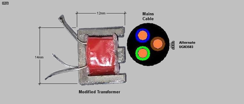
With total outside dimensions of 14 × 14 × 12mm, the modified transformer is small enough to be included in any suitable housing. As it weighs less than 5 grams, even with the rest of the circuitry included very little weight is added to the mains cable. The alternate UGN3503 Hall sensor is even smaller (and lighter), but it's not as sensitive. The minimum current it will detect reliably is around 500mA, but it ideally needs to be higher. The advantage is that you don't need to mess around modifying a cheap audio transformer.
The only critical part is to ensure that the cable is at a right angle with respect to the sensor, as shown above. If the laminations are in-line with the cable or if the cable is equidistant from each outer pole (i.e. directly on or above the centre pole), no signal will be detected. The sensor must be anchored to the mains cable so that it's held in the proper position for best sensitivity. The sensitivity varies dependent on the sensor's position on the cable, so you need to be able to move the sensor to get the maximum signal. For example, if the active and neutral are exactly the same distance from the mid-point of the sensor, the field cancels and there is no detection. However, by experimentation I found that this is actually hard to achieve, and even a small difference will provide enough signal to work with. Note that the peak sensitivity is when one current-carrying conductor is directly above one outer pole.
Of course, if you can access the active (live) or neutral, then current detection (with a current transformer or Hall sensor) is certain, and the magnitude (the amperage) is easily determined. This isn't required and as noted that requires a reasonably large junction box to allow the mains cable to be split so that just the active lead passes through the current sensor. It will require mains input and output connectors and will also house a small power supply. There is still a requirement to include an electronic trigger circuit and a connector that controls the external 'slave' device.
Having a unit that just clamps to the outside of the cable without having to change anything in any way means that equipment doesn't need any modification, cut cables or mains wiring. You still need a power supply, but that will generally just be a standard off-the-shelf switchmode plug-pack supply, which will usually never need to provide more than 2A or so. Suitable PSUs are readily available in all countries that suit the mains voltage used, and have the correct plug (avoid mains plug 'adaptors' as they are usually poorly made and very few work reliably).
In larger workshops (such as 'Men's Sheds' and the like) there will often be a number of people working on different machines at any given time. Where a dust collection system has been installed, it's generally preferred that the suction system (essentially a giant 'vacuum cleaner') has only those suction ports activated where a machine is operating. Some 'stand-alone' vacuum systems have an outlet for the power tool, and sense that current is being drawn to turn on the suction. This is an unrealistic approach for a workshop with many different tools.
A few commercial systems are available to detect that a machine is on, then activate a valve (often called a 'blast gate') that opens to allow sawdust collection to that machine. However, like most commercially available systems, they come at a cost. Part of that is the cost of the detectors, valves and control electronics, with additional expense incurred if (when?) a unit fails. Can it be repaired? Is the manufacturer still in business, and if not, can you get circuit diagrams (and sometimes specialised parts) to repair it? As for that last question, the answer is almost invariably "no".
If it can't be repaired or replaced, you may end up with a system that's no longer fit for purpose, and must be replaced entirely. This can be both disruptive and costly. Sometimes using generic parts that have been available for many years is the most sensible option, because they are entrenched in countless pieces of electronics and are unlikely to disappear any time soon.
Simple electronics that anyone with basic electronics knowledge can either repair or rebuild is wise, and is often by far the most cost-effective solution. A web search will reveal almost nothing - there are a (small) few circuits, but I wouldn't build any because they are seriously flawed. As for a schematic for the system installed at the Men's Shed I belong to ... nothing at all. Zilch. The system itself gets plenty of coverage, but nothing to allow anyone to fix a unit that's failed.
This is worse than unhelpful, so the only 'fix' for a failed unit is replacement. It's unlikely that you'll be able to get an exact match, requiring further modifications. The circuit described detects current in the same way as the system installed in the 'Shed'. Only the output section is different, as I consider the wireless system to be un-necessary for most workshops.
If you need (or think you need) wireless operation, you'll need to add the wireless system to the circuit shown. Many remotes allow for one press to turn on and another to turn off. These are not useful - you need a remote that uses two buttons, one for 'on' and another for 'off'. Without this, the system can easily enter a state where the suction is turned off when the machine starts and on when the machine is stopped. You can buy simple two-button remotes (transmitter and receiver) for under AU$20.00 each. Adapting them for the current sensor is up to the constructor, as this is something I cannot determine beforehand.
The idea that current can be sensed from the outside of a cable without breaking one conductor is counterintuitive, but it does work. What you cannot do is determine the magnitude of the current (how many amps), because there are conflicting magnetic fields that both reduce the sensitivity and make the output a semi-random proportion of the current detected. In this case, we only want to know that current flow is present, and the actual current is immaterial.
The modified small transformer will detect that current is flowing, but it may be necessary to reposition the sensor on the outside of the cable. If you happen to place the sensor so that it detects equal and opposite magnetic fields (both wires equidistant from the detector) the sensitivity is greatly reduced. It's possible to get an almost complete null, so current isn't detected at all. However, the null position is very precise, and almost all of the time getting a usable signal is quite easy. It's much harder to find a null!
The circuit requires a lot of gain, because the output of the coil is very low. Initial tests showed an output of about 2mV peak with a current of about 1A, so to detect current reliably means that the gain has to be at least 1,000 and preferably more. With a gain of 1,000 a 2mV signal is only increased to 2V, and this isn't enough to ensure reliable detection. Fortunately, we're only interested in low frequencies (50 or 60Hz), so even a very basic opamp can provide the gain needed.
Even with two opamps, the highest realistic gain we can get is around 100,000 (more is possible but we'd need faster opamps and risk oscillation or large DC offsets). Fortunately, a gain of 30k is enough to detect around 200mA, and the low-cost LM358 dual opamp is ideal. These opamps can use some extra roll-off, and the first stage feedback resistor is paralleled with a 10nF capacitor, giving a nominal -3dB frequency of 106Hz. The output of U1A is deliberately biased to only ~1.3V, which is reduced to 900mV at the output of U1B. With no signal the output MOSFET remains off. Note that with some LM358 ICs you might need to adjust the value of R2 to ensure that the output of U1B is greater than zero (down to 500mV should be alright).
However, when you have such a high gain, both noise and DC offset are inevitable. The important part is that the output level is low enough to ensure that Q1 can't turn on unless there's a valid signal from the sensor. Even though the sensor is effectively a short circuit for low frequency signals, its reactance increases with frequency, so it becomes more likely to pick up noise. The worst case is a motor or transformer nearby, but of course you can use the sensor to detect a motor's magnetic field rather than relying on picking up a signal from the cable.
The LM358 uses PNP input transistors, and the second stage of this circuit is DC coupled for simplicity. While you might expect a large DC offset, it's only about -400mV, so the output of U1B is 400mV lower than the 1.3V bias voltage on my prototype. AC coupling cannot be used, because it 'upsets' the output of U1B because the waveform is asymmetrical. With VR1 (the sensitivity control) at maximum, the circuit gain is 40,000 (about 92dB).
I suggest that the gain be variable, using the 2k trimpot shown. Alternatively you can just provide two ranges, so that different currents can be detected reliably. There's no point running maximum gain (~40,000) unless you actually need it, so reducing it as needed for high-current machines is a useful addition. Reducing the gain makes the circuit less likely to pick up stray magnetic fields. This can be done with a jumper, which is much cheaper than a switch or a trimpot. However, the latter has more control and lets you set the gain more accurately. The 'active' LED lets you set the sensitivity by monitoring the LEDs brightness.
The output section uses one half of another LM358, used as a comparator. Its output goes high when the voltage across C4 exceeds 6V, turning on the MOSFET. If you use the simple motor controller shown in Fig. 4, the relay isn't required, and the motor direction is determined by the MOSFET. When 'on', the motor is engaged in the 'Rev' (Reverse) direction, opening a suction valve or similar. When no current is detected, the MOSFET turns 'off', allowing the motor to reset itself to the 'Fwd' (Forward) position, closing the valve.
The relay (K1) is optional, and for interaction with the Fig. 4 actuator, the MOSFET will be a 2N7000 as it only needs to activate a relay in the actuator. The relay and/ or IRF540 MOSFET are only needed if the actuator you use needs them. This part of the project is just the detector, with the Fig. 4 actuator used if you wish to build your own.
As already noted, the UGN3503 Hall sensor is not as sensitive as the modified transformer, but for most motors it will probably be alright. The sensitivity control is not used in this version, and it's a simple matter to move the detector along (or around) the cable to get maximum LED brightness. Like the transformer, it's quite difficult to find a spot where you get no usable output, so there's no major disadvantage. The Hall sensor does require a regulated 5V supply though, and that adds a few parts. With the suggested circuit, noise is around 150mV, which is pretty awful. However, it's way below the MOSFET's turn-on voltage and does not cause any problems. Note: the input capacitor (C1) is reversed from the polarity shown in Fig. 2.
In both circuits, the first stage is an inverting amplifier, biased to about 1.3V. While the LM358 will work as a non-inverting amp with zero bias, it will not work without bias as an inverting stage. Both opamps are biased using the same supply. At the output of the second opamp, there will be an error created by the opamp's input offset, so the output voltage may not sit perfectly at 1.3V. In my prototype the offset was minimal (but measurable). The 'Active' LED is connected to the output of U1B so it provides direct feedback as to the current level detected. Predictably. the brighter the LED, the more signal you have.
To ensure that the DC offset doesn't turn on the MOSFET (Q1), two diodes are used in series. If you find that it remains on even with no signal, you may need to add one more. The 2N7000 is claimed to have a threshold voltage of as low as 800mV (0.8 to 3V, with 2.1V being 'typical'). While I've shown a miniature relay, you can just use the 12V output from the MOSFET, depending on the requirements of the peripheral unit (AC switching system, vacuum stop valve, etc.). Note that the maximum drain current for the 2N7000 is 200mA, but you can use an IRF540 or similar if you need more current.
There are two options for the output. The first is the relay, but if you only need a switched 12V supply that can be dispensed with. The second is the switched 12V supply, and if that isn't needed (or is only low current) the 2N7000 MOSFET is fine. If you need more current, the IRF540 is the most economical MOSFET that can switch up to a couple of amps without a heatsink. When used with a MOSFET output the ground is optional. Power is supplied to the external device when the MOSFET is on and the ground connection isn't used. When used like this, the 'Sw' output becomes the ground connection for the remote device (it's effectively a 'switched negative' output, which is perfectly valid if there's no shared ground connection).
The unit is powered from an external 12V plug-pack supply. This must have sufficient current capability to power the circuit (a couple of milliamps) and the external load if it's driven directly. Note that the external device will need its own power supply if it's expected to do anything 'interesting'. In this context, 'interesting' means a vacuum shut-off, an HVAC (heating, cooling, air-conditioning) motorised damper system or similar.
The most obvious control device is a relay, as that lets you signal to the remote device that current is flowing/ not flowing, and the remote (if a HVAC air control valve is used) simply steers current to the 'open' or 'close' terminals of the motor. These devices are (almost always) fitted with limit switches, so you can apply power for as long as you like without causing damage. However, you must follow the manufacturer's directions for operation as they will vary.
For the adventurous, you can use a wireless remote system rather than a wire. One thing that I know to be true is that a wire is far more reliable than any wireless system, but some may enjoy the extra challenge.
The circuitry (including the sensor) will typically be in a small plastic enclosure, with a screwed-down bracket on one side that clamps the mains cable into position. The alignment of the sensor and mains cable are fairly critical, so the bracket has to ensure that the cable locates directly above the sensor. In some cases you may need to slide the unit along the cable (±50mm or so) to get the best signal.
The opamp circuit is easily built on Veroboard. The circuit is pretty straightforward, and a Veroboard layout should pose no problems. The detector is mounted as shown below, and there's a lot to recommend cutting out a small slot through which the laminations protrude. They must not be proud of the exterior surface of the box though, as that may damage the cable's insulation. Having the laminations visible makes it easier to ensure that the cable is properly aligned.
The relay connections are best brought out using a 3-pin plug and socket, with many to choose from. Be aware that some control valves might require mains voltages to be switched, and if so the plug & socket must be mains rated and approved in your country. Hopefully this won't be necessary though as it adds greatly to the size and weight of the detector box.
DC will normally be connected with a standard DC barrel connector (5.5 × 2.1mm [outer/ inner] is the most common). The centre pin should always be positive. Reverse polarity protection is recommended, using a diode as shown in the schematic.
To set up, the box should be loosely attached to the tool's mains cable and the tool turned on. Adjust the sensitivity until the red LED comes on as brightly as you can get, then move the whole box along the cable by around 50-100mm. Find the points along the cable to where the LED is brightest, and adjust the sensitivity control until it reaches maximum brightness, but no further. Test it thoroughly until you are certain that it activates every time the tool is turned on. You only need to spend a couple of minutes on this, as it should be fairly easy to locate the optimum position. Tighten the screws that hold the unit to the cable and it's ready for use.
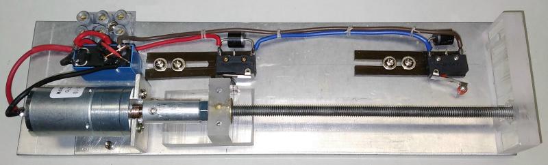
The next part is the actuator to operate your suction valve. An example is shown below, and the final arrangement depends on the valve you use. With the Fig. 4 arrangement, you can control a sliding vane in a flat housing, or you can re-configure the layout to use a rotary valve (typically a 90° swing is needed from 'off' to 'on'). Make sure that your motor is powerful enough to operate the valve under full suction. A good source of very capable motors is old battery powered drills (typically 12V types, using Ni-Cd battery packs). My prototype used one, and even with just 5V on the motor, it's fast (around 100mm/s with a 5V supply) and surprisingly powerful. It does slow down somewhat when loaded, which is good because 100mm/s is too fast.
The actuator is simple in concept, but it needs to be powerful enough to open a valve while it's under pressure from the vacuum system. Using a screw actuator gives an enormous gain in torque, allowing a comparatively simple arrangement to drive a fairly heavy load. The limit switches mean that the relay can remain activated or deactivated for as long as you like. Once the sliding actuator has reached either end, the motor is disconnected and no current is drawn. Fig. 4 is a hybrid drawing, showing both the mechanical and electrical parts. With a 6mm threaded rod, the distance travelled is 1mm/revolution. That means for (say) 100mm travel, the motor only turns 100 times. If you can find a motor with appropriate gearing, that would be preferable to direct drive.
The 'simplified schematic' lets you see just how the direction switching and limit switches are wired. Note that the motor at full speed will overrun the limit switch to some degree, so the lever needs to be flexible to absorb the overrun without being damaged. The 'alternate' schematic simplifies the wiring, as only two wires are needed for the limit switching. The diodes only conduct briefly, but they still need to be able to handle the motor's start current. 1N5404 or similar will be sufficient for all but the biggest motors you might use.
You can buy a linear actuator from any number of suppliers. There's a wide price range and a choice of extension ranges, from as little as 30mm up to 200mm. These are generally fairly low-cost, but some (especially high-load types) get expensive fairly quickly. Most are also fairly slow, ranging from ~5mm/s to 15mm/s, and that means your valve will take a fair while to open and close.
The DC input can be directly connected to the actuator, with a low-current 3-wire cable to the detector (positive, negative and relay). The cable can be any length you need, and anything up to 5 metres is perfectly alright. It's likely that you'll never need that much, but it does depend on the way your workshop is set up. You can use common 4-wire alarm cable, and parallel two of the wires for the ground connection.
My prototype detector unit is not fitted with the relay because it's not required for the actuator shown, but adding it to the circuit is easy to do. With an IRF540 MOSFET, provided the current is below 3A no heatsink is needed, and Q1 will dissipate less than 400mW. Driving the relay in the actuator only requires around 40mA for a typical DPDT (double-pole, double-throw) relay, so a 2N7000 MOSFET will be more than acceptable. If you need more, either use a MOSFET with a lower on resistance (RDS-On) or add a small heatsink. If a metal case is used that will be an adequate heatsink (assuming aluminium, not steel). The metal tab on the MOSFET must be isolated from the case.
The unit described here is intended to sense that a motor (on a fixed power tool) is powered, but it does not detect that the motor is actually turning. If you need a warning system then you should see Project 257, which is designed to illuminate a warning lamp when the motor is still turning - even after the power has been turned off.
This unit was designed to be used to turn on a vacuum system or similar, but it can also be used as a power-on detector for any purpose you see fit. It's not suitable for low-power equipment, as the minimum current it can detect is around 100mA (~23VA at 230V or 15VA at 120V) for the transformer based system (~500mA for the Hall sensor). I would not recommend it as a safety-critical detector though, because the sensor is external to all wiring and can be messed with by anyone (deliberately or otherwise).
The system described isn't limited to power tools, but it's doubtful that it will be of much use with audio electronics. The equipment used to trigger the circuit needs to draw a continuous current of at least 100mA, and that limits its usefulness for low-current equipment. I'm sure that people will find other uses for the detector though, as it is quite versatile. The ability to use it without disturbing any mains wiring at all is different from 'traditional' systems, eliminating the need for an electrician to install the sensor.
There are no references, but I did get the idea from a commercial system installed at the Men's Shed that I go to. When I saw it, it was a simple matter to work out how it must work, and the rest is history.
Note: There is a remote possibility that the sensor described infringes one or more patents, but I did perform a search with no results. I will not be making these units for sale, so no patent violation could occur. However, readers are warned that ESP projects are intended for personal use only, and if anyone were to build these units commercially they violate my copyright and may also infringe any patents that may exist. ESP is not responsible for any infringement, and the circuit and techniques described are for the purposes of education and providing ideas for home constructors and/or community organisations.
 Main Index
Projects Index Main Index
Projects Index
|