
|
|
| Elliott Sound Products | Project 257 |
This is definitely not an audio project, but it's still something that some audio DIY people may find useful. If you have a bandsaw in your workshop (or anything else that spins quietly), a moving blade can do you or your work some serious harm. The work can be replaced, but part of a finger may be more of a challenge.
This detector uses a commonly available 'ratiometric' hall-effect IC, such as the AH3503 or UGN3503 to sense a small neodymium magnet that's glued to the motor pulley. If the pulley is moving, an AC waveform is generated at the output of the hall-sensor, and this is amplified to operate a lamp. Normally, a high-brightness LED (or an array) will be used, but the circuit can power an external mains powered lamp if you prefer.
There are other ways to determine that a machine is running, one being a current detector. These are available as ready-made units, with most requiring external power. Some are self-powered, but they may not be sensitive enough for a machine that's operating with no load. While this isn't a bad option, it requires a case large enough to house a power supply, the current sensor, a couple of terminal blocks and mains input and output connectors. The case alone will probably cost more than the project described here. In most cases, a timer is also needed to keep the warning light on for long enough for the machine to stop. This all adds up to a fairly expensive unit.
A good example of a current-sensing switch is Project 79, and while it will certainly perform just as well as commercial offerings, it has the same limitation. By default, it will turn off the load (in our case here a lamps or other warning system) as soon as the main load current stops, so it would need a timer to keep the warning system active for long enough for the machine to stop. It's easily done, but it still requires mains wiring, something that the unit described here does not.
I must point out the obvious though. A red light (however bright you make it) cannot prevent injuries. What it will do is make people aware that the machine has not stopped after it's been turned off, and if properly positioned so it can be seen from any angle, it acts as a warning. Any form of safety barrier can't be used on a machine that requires us to work close to the blade, so care must still be taken when using the tool. The system described is intended to warn both the user and bystanders that the blade is (still) moving.
The hall sensor is mounted on a bracket that can be formed to position the sensor within ~3-5mm of the magnet as it rotates on the pulley. The circuit is fairly sensitive, and you should be able to get a good signal from up to 8mm away (depending on the magnet's strength). The sensor's output is amplified by 100 by U1A (a cheap & cheerful LM358), which is operated with no input bias voltage. The LM358 is one of the few opamps that can be used this way.
When the machine is running, the AC waveform from U1A is 'detected' by D1, which charges C4. When the voltage across C4 exceeds 2.2V (set by R6 and R7), the output of U1B goes high, turning on Q1 to power the LEDs. A relay (with anti-parallel diode) can be used in place of the LEDs if you wish to power an external (mains operated) lamp or anything else deemed necessary for your workshop (see Fig. 2). The points indicated as 'A' and 'B' are used with the optional output drivers.
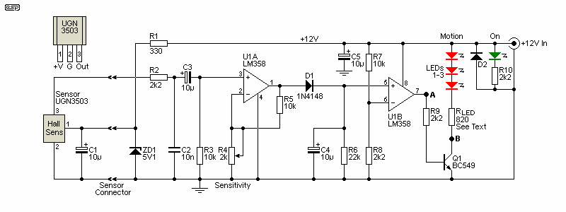
The circuit is very simple, and uses a basic zener diode regulator for the hall sensor. Depending on the sensor used you may need up to 13mA, so R1 is selected to provide 20mA to the 5.1V zener. With the recommended 12V supply, that means a 330Ω resistor. The output from the hall sensor is filtered to keep anything above 7kHz out of the detector, as that minimises the likelihood of noise causing a false signal. With a single magnet on the pulley, the output frequency is a pulse waveform at 20Hz for a nominal 1,500 RPM motor. If you want to know the frequency for any motor, it's ...
f = RPM / 60
Be aware that the pulse width may be quite narrow, and that precludes using a more aggressive input filter (yes, I was caught by this). If the magnetic field occupies (say) 2% of the pulley circumference, then the duty cycle of the output waveform is also about 2%. This means that while the frequency is quite low, the circuit has to be fast enough to 'catch' the brief magnetic pulses as the magnet whizzes by for each rotation. Adding one or more extra magnets may be helpful if you have trouble getting a reliable signal.
The 2.5V DC offset from the sensor is blocked by C3, and the lowest frequency that will be detected is 0.15Hz (9 RPM). If required, this can be reduced by increasing the value of C3. Alternatively, you can glue extra magnets to the motor pulley. Two magnets mean two pulses per revolution, but more than three probably won't be needed. Accurate placement on the periphery of the pulley is not required, as long as they are all the same height.
U1A has a variable gain - from a minimum of six up to around 100. The gain is adjusted using R4 (a 2k trimpot), and should be set so that rotation causes reliable detection. The output of U1A is used to charge C4 via the diode. When the voltage C4 exceeds 2.2V, the output of U1B goes high. While I've shown a transistor as the switch, you can use a MOSFET if you think you need to drive a higher power load. There is a deliberate (but short) delay after the last pulse before the red LEDs turn off. This can be altered by changing the value of R5 (10k). A higher value gives a longer turn-off delay.
RLED is selected to give the desired LED current, based on the number of LEDs in series. Three works well, and will have a voltage drop of around 8V. Decide on the desired current (10mA is a good starting point), so RLED will have 4V across it, and the nearest standard value is 390Ω. To save on the number of different value resistors needed that can be reduced to 330Ω, giving 12mA LED current. If you use ultra bright LEDs you should limit the current to about 10mA - I used ultra-bright, with an 820Ω limiting resistor which gave a LED current of about 8.5mA. If you need more LEDs, simply duplicate the string shown, including the resistor. The transistor can drive 3-4 strings at 10mA each.
Note that D2 is intended to prevent damage due to reverse polarity. Its current rating needs to be the same as the supply, so if you use a 2A DC supply, you need a 2A diode. A 1N5401 diode will generally suffice, but something larger may be required if the supply is capable of higher current. A diode can be used in series with the supply, but that reduces the supply voltage a little. If you do use a series diode, it should be a Schottky type for minimum voltage loss. If you only ever use centre-positive DC connectors the diode can be omitted.
A hall-effect detector isn't the only option, but it is the simplest to implement. Mechanically it only needs one (or more) magnets to be stuck to the motor pulley, and a small adjustable bracket to position the detector itself (see Fig 6). You could also use a photo-interrupter, but they are more fiddly to set up and may require a light shield if the housing isn't light-tight. An opaque vane of some kind is glued to the motor pulley and cuts the light beam between the photo-emitter and detector. There is no doubt that this is an effective technique, but the mounting bracket needs three axes of freedom to ensure that the vane passes cleanly through the rather narrow slit of a typical photo-interrupter (typically around 5mm but it may be as small as 1mm). Much too fiddly to set up, and it requires a level of precision that's not sensible. In theory you can also use a coil pickup, but the output level will be very low (requiring more amplification). This is not recommended.
The same circuit can be used with a photo-interrupter as for the hall sensor, but you may not need as much gain in the first stage. The circuit is designed to respond to AC only, so DC levels are irrelevant. This is important, because the motor may stop with the magnet (or vane) right at the sensor position. This would create a 'false positive' - i.e. indicator on but no rotation. I selected a hall sensor because they are tiny, far easier to mount than a photo-interrupter and are generally cheaper as well. There are no downsides to the hall sensor, other than the requirement to glue a magnet onto the motor pulley.
The circuit is powered from an external 12V supply, with a current rating to suit the switched load (assuming LEDs). A single supply can power several detectors if that's what you need. The typical current draw will be less than 50mA will all LEDs on. Most 12V plug-pack supplies are rated for around 2A, more than sufficient for several detectors. The separate 'On' LED is optional but highly recommended. It lets the user know that the circuit is powered without having to turn on the saw (etc.), so it represents another safety factor. If the green LED isn't on, the unit has no power so won't indicate that the motor is turning!
The two options (MOSFET and relay) can be used instead of, or in conjunction with the internal LEDs. A 'fully equipped' unit would have its on-board LEDs, the MOSFET, and the relay. These combinations make the unit very versatile, allowing it to be used with any load you're likely to need. The relay can switch mains if required, allowing the detector to turn on a work lamp whenever it's operating. I leave the final decision to the constructor, but be warned that if the relay is used to switch on mains voltage (i.e. 230V or 120V AC), the case will be much larger and will need mains input and output leads or connectors. The relay is shown in the most basic form, and the external device can use either the normally open (NO) or normally closed (NC) relay terminals.

The DC output driver uses a MOSFET to power an external 12V load. This can be a bigger (and brighter) lamp, mounted somewhere such that it cannot be missed. You can include a beeper or other warning device as needed for your workshop. The IRF540 can drive a load of up to 3A easily without needing a heatsink. Needless to say, the power supply you use must be able to supply the required current (with a safety margin). For example, if the external load draws 2A, I recommend a 12V supply that can supply at least 3A, because not all can deliver their rated current without the voltage sagging. Note that the negative terminal is not common to anything, so if you use a metal enclosure the negative must be isolated from the case.
The circuit will typically be on Veroboard, with a separate tiny piece used for the hall sensor. The bracket is something you'll have to work out for your application. Make sure that it is well damped to prevent mechanical oscillation when the tool is in use. Nothing is critical, but the bracket should have adjustment to obtain optimum clearance from the pulley and attached magnet (bending it to suit is perfectly alright). My tests indicate that a clearance of up to 5mm will probably be fine, depending on the magnet strength.
The main electronics will most likely be in a small box with a suitable connector for the DC input and a 3-pin connector for the detector. I used a miniature 3-pin plug and socket for the units I built for the Men's Shed. You can also use a DIN connector - possibly not the most ideal, but they are reliable in use and are fairly cheap. Feel free to use whatever connector you desire. This includes tip-ring-sleeve (stereo) jack plugs, but they can be affected by even slight corrosion.
You will need to route wiring from the motor pulley area up to the display box position that's suitably visible, and a number of small holes may be drilled into the bandsaw housing for mounting the sensor bracket and the indicator unit (and for wiring). Make sure that any wiring cannot come adrift, because if it gets caught by a pulley or the blade it may cause significant damage. Be aware that some industrial bandsaws use fairly thick steel, and you may prefer to attach everything using strong double-sided adhesive tape (carpet tape or similar) and/ or construction adhesive. Another option is to use strong magnets, ideally those with a countersunk hole for a mounting screw. These can be supplemented with super-glue, ensuring a permanent bond.

If possible, the magnet and sensor should be at the back of the pulley, so the sensor doesn't have to be removed to replace the drive belt. This may be impractical with some machines, so you need to adapt the mounting bracket to suit. If you use a clearance adjustment screw as shown in the drawing, it should be locked with superglue or Loctite so it can't move due to vibrations. Use just enough to prevent movement, without fixing it so firmly that it can't be moved later. If there's no alternative but to mount the sensor in front of the pulley, the bracket needs to be made so it can be removed and replaced without affecting the clearance to the magnet (or allowing it to be reset easily). The alternate mounting shown is suitable where there's no space behind the pulley. The screws can pass through slots to allow easy adjustment as shown in Fig. 6. The sensor bracket can also be attached using magnets, but they must be strong enough to ensure that the sensor can't move.
The bracket can be fabricated from 3mm acrylic, which is very strong and easy to cut with a hacksaw. It's also easily bent to shape using a hot air gun to soften the plastic, after which it can be bent to the desired shape. You need to hold the shape until it cools, and if you make a mistake just re-heat it and make the correction needed. It can be drilled and tapped to accept 4mm metal-thread screws, and it's the most versatile way to make weird brackets (useful for other projects as well). If needed, it can also be glued with cyanoacrylate (super-glue), with or without accelerator spray. Glued joints using cyanoacrylate are surprisingly robust, but the two mating surfaces need to be in intimate contact.
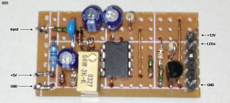
To give you an idea of the layout, the above shows my prototype. It's very compact, measuring only 40 × 23mm, with a total height of 15mm, the latter due to the trimpot. The only part not on the board (other than the LEDs) is the series resistor for the green LED (R10). Because I have a fairly good supply of 0.125W resistors I can fit two leads into a single hole where needed. This is convenient (and makes the board smaller), but it's certainly not a requirement. If you can't do that, the Veroboard will be about 5mm longer.
The units I built have internal LEDs inside a piece of 10mm thick clear acrylic, and the case measures just 75 × 42 × 25mm (L, W, D). It's very compact, but the four high-brightness red LEDs I used are highly visible. Naturally, it needs to be located where it's easily seen by anyone near the machine.
My prototype units are not fitted with the MOSFET, but adding it to the Veroboard is easy to do. Provided the current is below 3A, no heatsink is needed, and Q2 will dissipate less than 400mW. If you need more, either use a MOSFET with a lower on resistance (RDS-On) or add a small heatsink. If a metal case is used that will be an adequate heatsink (assuming aluminium, not steel). The metal tab on the MOSFET must be isolated from the case.
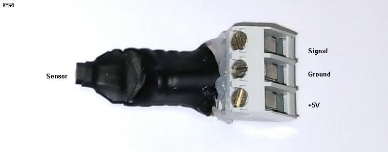
The sensor is shown above. It needs a terminal block, because no-one wants to be messing around inside a bandsaw with a soldering iron. Like the control board, it's built on a tiny piece of Veroboard, and that carries the sensor itself and a 10μF bypass capacitor (as shown in Fig. 1). The board can be attached to the mounting bracket with hot-melt glue and a cable tie. There are countless way it can be done, and the above is just a suggestion.
The image is many time 'life size', and the units I built are 35mm long, 15mm wide (to accommodate the terminal block) and 15mm high. Most of the height is also due to the terminal block. The sensor is at the left, just protruding from the heatshrink tubing. The whole assembly weight just 5 grams, so 'robust' mounting isn't required. I mounted the sensor to the bracket (section 'C' below) using hot-melt adhesive, and added a small cable tie to make sure it cannot fall off.
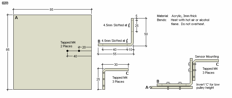
The brackets I made followed the general idea shown above. The dimensions aren't critical and can be adapted as required to suit the pulley arrangement on your machine(s). I used 3mm acrylic which is easy to work with, and can be bent after heating. It's not hard to make the slots, which allow the two bent sections to be moved far enough to allow for misalignment of the base plate. The latter will typically be mounted using double-sided tape, but I strongly recommend that you augment that with construction adhesive. After a few years, even the best double-sided tape can decide to spontaneously let go. Before attaching anything to the inside of the machine, clean the area thoroughly using acetone or similar solvent.
Some bandsaws (and other mains powered tools) use a magnetic brake that turns on when the motor is switched off. From personal experience I can tell you that the brake will almost certainly activate the red LEDs. This isn't a problem, but it adds a delay after the blade has stopped moving.
Don't underestimate the ability of any power tool to cause serious injury. bandsaws are generally considered 'benign', but that's not true at all. A bandsaw is just as dangerous as any other saw, but we are used to using them at (sometimes very) close quarters. This brings a sense of familiarity, and as always that can lead to bad outcomes. Any machine that has not stopped completely after use is a potential hazard. Some can run for 10 seconds or more after power is turned off, and while that doesn't sound like much, it can easily be enough to cause someone an injury.
This is especially true in a shared workshop environment, where people may not always turn off a machine (or wait until it has stopped) before walking a few paces away to get the next thing to be cut. Added to this is the overall noise in shared workshops, so your chances of hearing that the machine is running (or slowing down after power-off) are dramatically reduced.
In my own workshop, I know when the bandsaw is still running (or hasn't stopped yet) because my workshop is otherwise quiet, and any noise is audible. I know that this is absolutely not the case in a shared workshop. Indeed, this project was inspired by a query from another member of the 'shed' who was injured by a bandsaw that had not stopped! Fortunately his injury was not serious, but hopefully this unit will prevent it from happening again.
Surprisingly, the reliability of the unit is somewhat critical. People will get used to it being there, and if it stops working someone may get caught out. This could lead to serious injury, so a 100% reliable (insofar as that is possible) is a requirement. That means no stressed components, a reliable external power supply, and safeguards to ensure that no wiring can be disconnected by accident.
Apart from the bandsaw for which this unit was devised, another machine that can cause significant injury is the jointer (aka joiner). To my mind, these are probably one of the most dangerous machines made, because they are very quiet when running, and have rapidly spinning blades that project above the table area. Yes, there's a guard, but by design it moves freely to expose the blades. The jointer in the Men's Shed already has a serious detector circuit that operates both a light and a loud beeper. Before it was installed, it cause one member a serious hand injury! The circuit shown here can easily be added to if greater protection than a few red LEDs is needed. As noted earlier, the transistor can operate a relay that can turn on anything you like.
There are no guarantees, but since this project seems to be somewhat unique (despite the wide applicability of such a device), a PCB might be offered at some point. It's a far less expensive (and more reliable) arrangement than using a COTS (commercial off-the-shelf) current sensor, separate timer and chassis mount power supply that I've seen used. If other Men's Sheds in Australia decide they'd like something similar, then a PCB becomes mandatory. Not that many people are comfortable with Veroboard layouts, so a proper board will probably make someone's life easier.
Meanwhile, this is a recommended addition to power tools, especially those that use exposed blades. Many other tools (table routers being but one) will benefit from having a visual warning, although some are so loud that they don't need anything extra - unless there are hearing impaired members of course! As always, the design is free for anyone to build for non-commercial purposes, and Men's Sheds are a definite target area.
Other than the datasheet, there are no references, as this is an original design.
 Main Index
Projects Index Main Index
Projects Index
|