
|
| Elliott Sound Products | Project 231 |
 Main Index Main Index
 Projects Index Projects Index
|
For various reasons, you may need (or want) to use a discrete opamp rather than an integrated circuit. One common requirement is for more output voltage than you can get with an opamp running from a ±15V supply. A few ICs can handle more, but most recommend no more than ±18V. It's not often that this causes any issues, but there's no doubt that it can be limiting. Another requirement may be high speed, with a slew rate of 20V/µs or more. You can get opamps that satisfy these criteria, but they are relatively uncommon and therefore rather expensive.
Two discrete opamps are described in Project 07, dating back to 1999. They are still worth a look, but cannot provide the same performance of the one described here. In particular, distortion is a little higher, but the simple version saves one transistor and three resistors. That is of no consequence unless space is at a premium. Another version is Project 37a, which uses current feedback. It's been available (including a PCB) since 1999 (originally P37, single supply), and it works surprisingly well for such a simple circuit. THD is around 0.05%, not 'stellar' but it's predominately low-order.
If you build a discrete opamp, it's not difficult to allow operation at up to ±25V, and even higher supplies may be able to be used with the right transistors. One thing that a DIY opamp will not have is output protection, so a shorted output may result in transistor failure. For the schematic shown below, output current is limited to about ±20mA.
The design here is a 'true' opamp that has much the same characteristics as an integrated version, but with much wider bandwidth. With no compensation capacitance, I measured the response to 600kHz with 10V RMS output, and with an output of 3.7V that extended to 1.4MHz. The slew rate measured ±22V/µs. There are a few IC opamps that can match this, but usually at some expense.
However, in its base form it is likely to oscillate if the output is loaded with any capacitance, as it's marginally stable. With a nice resistive load it is well behaved. The measured distortion (gain of 6.9 or 16.7dB) was at my measurement threshold, 0.002% THD + noise. The simulator I use claims 0.0018% THD, so there's good agreement. The distortion residual was well below the noise, but is low order.
One thing that you can see is that it's perfectly symmetrical - to look at! NPN and PNP transistors are different from each other, so the idea of a symmetrical circuit is an illusion. Many circuits ate touted as being 'better' than others because they are symmetrical, but it's only visual symmetry. Asymmetrical circuits often perform better than those that claim 'perfect' symmetry.
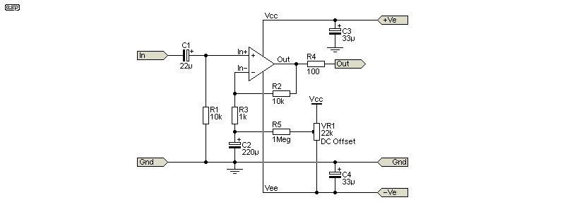
I made no attempt to match the transistors, so DC offset is far higher than any IC opamp. With a 100k input resistance and full DC feedback, I measured 16mV offset. That's not an issue with AC coupled circuits, but it will cause problems if they are DC coupled. It's not difficult to add DC offset correction if it's required, and that's shown later.
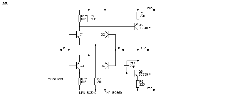
Don't expect to be able to drive low-impedance loads, because the circuit doesn't have enough open-loop gain or output current to allow that. I didn't measure it on the real circuit, but the simulator tells me that open-loop gain is around 70dB (x 3,162). That's low by comparison to most modern opamps. On the positive side, there's very little high-frequency rolloff unless C1 is increased from the 22pF shown, so there's plenty of feedback available at high frequencies. Even with the 22pF cap, there's still 45dB of gain at 100kHz. While fairly impressive, it doesn't even come close to an LM4562.

If the value of R1 and R2 is increased, the output current is increased too. Up to 10k should be sufficient, as that gives a quiescent current through the output transistors (Q5 and Q6) of about 9.5mA with ±25V supplies (it's 4.6mA with 5.6k). With 10k and ±15V supplies, the output stage quiescent current is just under 4mA.
The input consists of two differential pairs, one NPN and the other PNP. They are 'complementary' in that they have opposite polarities, but unless the four transistors are matched for gain and VBE (base-emitter voltage) the input currents will not cancel completely. The output stage is also 'complementary', using Q5 and Q6, with the collector current determined by the voltage developed across R1, R2, R5 and R6. The final collector current is controlled by the 'tail' current for each differential pair (368µA with 39k), set by R3 and R4. It should be apparent that everything depends on everything else, as it common with all direct-coupled circuits.
The collector current through Q1-Q4 is about 184µA with the suggested 5.6k resistors. For best performance, the current through each transistor should be equal. In reality, many things will conspire to upset the balance (in particular hFE and VBE), but if you just use random transistors as I did for the prototype it will work well enough for most purposes. Don't expect particularly low DC offset voltages though - mine measured 14mV with 100k resistors at the input and feedback.
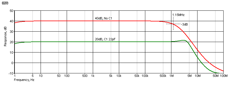
C1 is optional. If the circuit oscillates it will be needed (a second Miller capacitor between base and collector of Q5 is another option). If you use two Miller caps, the value can be halved (e.g. 10pF each). Depending on your layout and load, the value may need to be increased, with up to 100pF being needed in extreme cases. I tested the circuit with an 82pF cap (I didn't have a 22pF cap available when I ran the tests), and full output is available at up to 50kHz. With an 82pF cap installed, the circuit performs faultlessly for all frequencies within the 'extended' audio range (5Hz to 50kHz). The circuit can be used without the Miller cap for high-gain applications. I tested my prototype to over 1MHz (-3dB) with a gain of 100 (40dB).

The response was plotted using the simulator. Having tested the amp fairly thoroughly, I know that the response shown matches reality fairly well. The full output voltage isn't available at the upper frequency extremes, but getting 2V RMS output at over 1MHz (40dB gain) is easily achieved. This is more than enough for most applications, and consider that 40dB is a lot of gain. 2V output is achieved with only 20mV input. It is possible to have even higher gain, but noise will become a real problem.
The small rise in output at 2.75MHz (20dB gain) is real, and it can be reduced by increasing the value of C1. It's a rise of ~1.4dB and won't cause any problems for normal audio applications. With 10k and 1k feedback resistors, the gain is actually x11 (20.83dB), and if you need exactly x10 gain, you'd could use 18k for R2 and 2k for R3. In most cases the difference is academic. The simulation used 9k (6.8k + 2.2k) and 1k.
The output stage operates in Class-A, so there is no crossover distortion. However, the peak output current (into the feedback network and load) cannot be allowed to fall to zero or distortion will rise dramatically. The minimum supply voltage is ±10V, and if you use the maximum (±25V) R1 and R2 should be no higher than 5.6k or dissipation in Q5 and Q6 will be too high. For ±25V operation, Q5 and Q6 should be BC639 and BC640 (NPN and PNP respectively). For 'normal' ±15V supplies Q5 and Q6 will be BC549/559, with slightly better performance.
The circuit is used like any other opamp, which means it requires a negative feedback circuit, an input resistor to ground and proper supply bypassing. Because it has much wider bandwidth than most integrated opamps, it's more sensitive to capacitive loading and/ or poor bypassing. A 100Ω output resistor should be considered mandatory in the complete circuit, as shown in almost every ESP project.
It's possible to build the circuit using all SMD parts, but that poses many challenges. A PCB is essential, which you will have to design for yourself. If there's enough interest I may consider designing a board (for through-hole, not SMD), but I suspect that's fairly unlikely. When the cost of a PCB and the parts is added up, you can buy an AD797 opamp for the same price. The AD797 is one of the highest performance opamps available (except if purchased from eBay sellers - those available will almost certainly be fakes). However, even the AD797 opamp can't achieve 40dB gain at 1MHz.

There's no difference in the way the opamp is used in a circuit compared to an IC version. If you don't match the gain (and the base-emitter voltage) of the two long-tailed pairs (Q1, Q2 and Q3, Q4) and need DC offset to be low, you'll need to include the offset adjustment. Because the input transistors are not in thermal contact with each other (at least with most home construction methods), the offset will change with the ambient temperature. It's unlikely to be a problem though, and if you need good DC offset performance you're much better of with an IC opamp.
The ability to get a signal gain of x 100 with an upper -3dB frequency of 1.4MHz is hard to beat. If the gain is reduced to x 10, it's flat to over 4.5MHz (at least in theory). Reality will be different of course, but I measured flat response to 1MHz with a gain of x100 (40dB). With the same and at an output of 2V RMS (20mV input), the distortion (THD+N) was 0.03%, but all of that was noise! In terms of harmonics, I couldn't measure any. The simulator can exclude noise, and it claims 0.003% THD which is in line with my expectations.
Noise is easily seen with low input voltages, and I measured 800µV broad-band. Assuming a bandwidth of 50kHz, that translates to an equivalent input noise of about 3.5nV/√Hz, which is better than I expected. It may be possible to get lower noise by increasing the current through Q1-Q4, but the difference is probably not worth the effort. The values of all resistors have to be re-calculated if you were to do that. If you really need a high gain, low noise test preamp, have a look at Project 158 - Low Noise Test Preamplifier. This is my 'go-to' preamp for measuring output noise or amplifying very low signal levels (down to a few microvolts).
Discrete opamps that can be built easily will never outperform most ICs other than in very specialised cases. While it can also be used for hi-fi and can give a good account of itself, decent IC opamps will outperform it easily. The most likely use for it will be where you need a lot of gain with a wide bandwidth. This can also be achieved using two (or more) IC opamp gain stages, selected for wide bandwidth. Multiple stages can be used in series to get both the gain and bandwidth you need.
Three stages using even TL072 opamps can get 60dB of gain up to 100kHz (-1dB) with a -3dB frequency of about 180kHz. In reality this would be a bad idea because they are rather noisy, and you'd have at least 2.5mV of noise at the output (20kHz bandwidth), even ignoring resistor noise and assuming a shorted input. This will increase to about 5.7mV of noise with 100kHz bandwidth. This is significantly worse than the discrete version described.
This project is designed for experimenters. While it's a nice little circuit, it can never match the performance of many modern opamps. This shouldn't deter anyone from building one of course (I did), and by doing so you learn more about circuitry in general, and opamps in particular. Because this particular opamp is rather fast, it's well suited to metering, which pushes most opamps to their limits. Even this one is limited to about 250kHz, which demonstrates that meter amplifier/ rectifiers are 'difficult'. This is because the opamp operates open-loop (no feedback) for at least ±700mV, and a very high slew rate is essential.
There are two primary benefits of discrete opamps. The first is that building (and testing) one improves your understanding of how they work, and how each part interacts with the others. The second reason is that you can optimise a circuit for a very specific task. For example, you can modify the output current capability by altering the quiescent current through the input and output stages. You can ensure that the circuit remains stable for a given closed-loop gain by changing the value of the Miller capacitor(s). You can even add stages to increase the gain, but may find that the circuit becomes impossible to stabilise against oscillation.
These are all tasks that IC designers face when they develop a new opamp, and why should they have all the fun? Ok, it's not so much fun when you find that your final design is easily beaten by a commercial opamp, with input current, input offset and other factors all beaten easily by something you can buy for a couple of dollars. However, in terms of the knowledge you can get by building and analysing the circuit, it becomes a winner. Good knowledge of analogue circuitry is something that used to be fairly common, but it's now poorly understood by the majority of experimenters.
There is no doubt whatsoever that an IC opamp will (generally) perform better than the circuit described, especially for noise and distortion (opamp dependent of course). However, few can match its performance for bandwidth, especially with high gain. There are no 'audio' applications that need 1MHz bandwidth with 40dB of gain, but it may come in very handy for instrumentation (test and measurement) circuits. Despite the mediocre DC offset performance, it's well worth building just so you can experiment with it yourself.
The circuit shown is based on a similar design that was used by an Australian company called Auditec. They made power amp modules and other audio gear, some of which were fully built, with others as a kit. The discrete opamp was used as the driver stage for a power amplifier. It's been simplified and rationalised compared to the original. There are no references to the design on the Net (despite a lengthy search). There is one 'hit', and it's a forum for a Hi-Fi magazine. The amp was designed by Cyril Murray, and dates to the early 1980s.
 Main Index Main Index
 Projects Index Projects Index
|