
|
| Elliott Sound Products | Project 07 |
 Main Index Main Index
 Projects Index Projects Index
|
It seems that the poor old op-amp is a device that many people loves to hate, even the really nice ones that come from Burr-Brown (now Texas Instruments) and Analog Devices. Opamps such as the LM4562 are almost impossible to beat with any discrete circuit. There is nothing to indicate that an IC opamp with distortion below 0.001% will sound 'worse' than a discrete circuit. The many claims of opamp 'sound' are generally due to non-blind test methods and are mostly (but not always) false. Real differences exist with noise, but for competent opamps, frequency response and distortion are generally far better than anyone can hear. In particular, claims that one opamp has 'better' (more 'authoritative') bass seems to be a popular piece of BS. These claims are clearly false when both devices tested have perfectly flat response to DC!
One opamp that should not be used for audio is the LM538. It's fine for support circuits (clipping detectors, limiter side-chains, etc.), but it has high distortion due to an un-biased output stage. See the article Opamps - A Short History - The Most Famous Opamps Of All Time (Or Not) for details of opamps in general.
NOTE: The circuits presented are experimental, and should provide some fun to build and play about with. Both have been built and tested, and they work very well indeed. Please note that these are low current Class-A opamps, and are incapable of driving low impedances. The minimum recommended load impedance is about 1k.

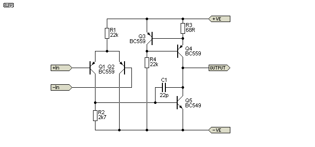
Figure 1 - Discrete Op-Amp
It has the advantage of a Class-A output stage, so there is no possibility of crossover distortion, and in the version shown, (my simulator tells me that ...) using transistors with a gain of 100, the final circuit has an open loop gain of 5,400. The Class-A output runs at a current of 11mA, and the circuit should work fine with supply voltages from ±12 up to ±20 or more (depending on the voltage rating of the transistors).
The circuit shown was both tested and simulated with ±20V supplies, and different supply voltages (as well as variations in the transistor characteristics) will require that the value of the 2.7k resistor (R2, between base and emitter of Q5) will need to be changed to minimise DC offset. This also ensures that the collector currents in the LTP are equal, maximising gain and minimising distortion. A 5k multi-turn trimpot can be used here to set DC offset to 0V.
The frequency stabilisation capacitor will need to be selected based on the closed loop gain - in some cases it may not be needed at all. Unless you have decent test equipment to verify that the circuit is stable, leave it in. Be very careful if the load is capacitive (or worse, a resonant circuit, such as coaxial cable) - the circuit will almost certainly oscillate. If this happens, use a 100 ohm 'stopper' resistor at the output. It must be after the feedback return, otherwise it will do no good at all.
Note: With 22pF as shown, the circuit is not stable if used as a unity gain non-inverting follower (it will oscillate).
If you need a non-inverting voltage follower (aka unity gain buffer), the value of C1 will need to be increased. With the value shown, it should be stable with a gain of two or more. As a unity gain buffer, try a value of 100pF for C1. The circuit has an open-loop gain of about 64dB (×1,680), and it can be used as a comparator.
Because the circuit is an opamp, it needs to have feedback resistors and a DC return path for the +ve input - just like any other opamp. Performance is very good with gains of up to 10 (perhaps more depending on what you want to use it for), and it can be made to have very wide bandwidth.
The suggested transistors are cheap, easy to get, and pretty good, too - to get the best performance, use the highest gain versions ('C' suffix).
NPN - BC549C
PNP - BC559C
As always, use 1% metal film resistors for low noise and long term stability. Ideally, Q1 and Q2 will be matched for base-emitter voltage and should have matched hFE as well (if possible). When they are installed, it's a good idea to bond Q1 and Q2 together with a cable tie and some thermal 'grease' between them. This helps to ensure that their relative temperatures are equal to prevent DC offset drift. Even a 10°C temperature difference is more than enough to cause a DC offset of around 18mV (as simulated - it's generally accepted that VBE changes by -2mV/°C, but it also depends a little on the current).
However good this may look, I can safely assure the reader that it doesn't even come close to something like the NE5532 dual op-amp, and it draws a lot more current, too. However, it is an interesting circuit to fool about with, and should actually give a good account of itself in traditional op-amp circuits.
One word of warning - the input impedance and bias current are much worse than even the poor old 741, but bandwidth, noise and distortion can be expected to be much better. Just don't try to use it with really high impedance circuits, and don't expect the output to provide the ±20mA or so you are used to, because it won't. However, Project 37A is an excellent audio preamp that is based on the general ideas shown here, although the approach is different. In some cases, there are few choices - you end up having to use discrete and 'outdated' circuitry, because no available (or affordable) opamp has the required bandwidth.
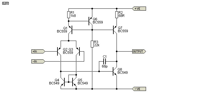
If you'd prefer something with higher performance (in particular better common mode rejection and higher open loop gain), the second version shown below is worth a look. It uses a current source for the input long-tailed pair, so it has a wider operating voltage range (it will work from ±2.5V supplies or a single 5V supply). The current source improves input common mode rejection, as does the current mirror (Q4 and Q5).

Figure 2 - Alternate Version Of Discrete Op-Amp
You can add emitter resistors on the LTP, which help improve the matching of the two input transistors, but they do reduce open loop gain a little. Around 22 ohms will work in the emitters of Q2 and Q3, but if the transistors are well matched there's not much to be gained. The current mirror improves gain and reduces input transistor DC offset. Open-loop gain is 12,000 (80dB) up to 1.3kHz (-3dB frequency). In this version, Q2 and Q3 (the LTP) should be matched for VBE and so will Q4 and Q5 (the current mirror). Both pairs should be thermally bonded as described above.
Despite the higher component count for the Figure 2 version, it still won't equal a decent opamp for noise and distortion, but it is possible to get a much higher upper frequency response. You will most likely need to experiment with C1, depending on the gain set by the feedback network. It should be possible to get a closed loop gain of up to 10 with response extending to 2MHz. This could be useful for an instrumentation amplifier driving a 100µA moving coil meter (for example).
The circuit can be further enhanced by adding an output stage so the Class-A amplifier stage (aka VAS - Q8) is isolated from the load. Use of a 'super-matched' transistor pair for the LTP and current mirror will provide much lower DC Offset, but the circuit must be re-arranged so the LTP and current mirror use NPN devices (super-matched pairs aren't available in PNP). There are several other changes that can be made, but it still won't equal an LM4562 or LME49860 (the latter can use higher supply voltages - up to ±22V).

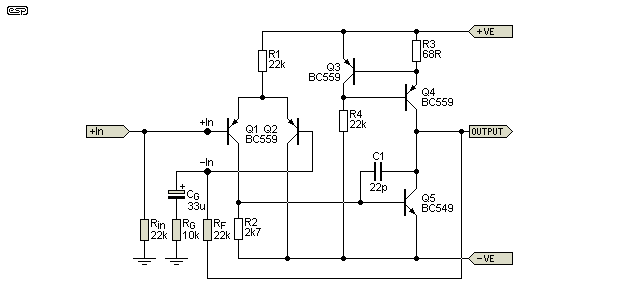
Figure 3 - Discrete Op-Amp With Feedback Components
A discrete opamp is used just like any other, as shown above. The feedback is via RF and the gain is set using RG. The values shown are suggestions only. CG ensures that the circuit has unity gain for DC. An input capacitor isn't shown, but is essential if the source has any DC present. Note that the polarity of the feedback capacitor (CG) may need to be reversed if there's a negative voltage at the output. A few millivolts isn't a problem though, and electrolytic caps can handle up to 100mV reverse polarity without any problems (long-term or otherwise).
If you only need a unity gain buffer, the output should be connected directly to the inverting input, and C1 will need to be increased. The value should be at least 100pF, but you may need more if you see any sign of ringing at the output with a squarewave input signal.
 Main Index Main Index
 Projects Index Projects Index |